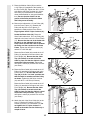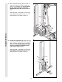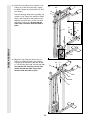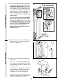
1
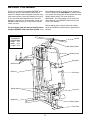
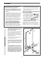
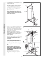
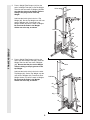
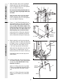
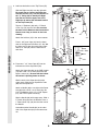
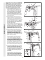
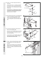
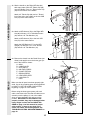
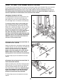
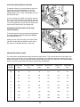
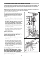
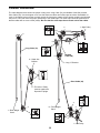
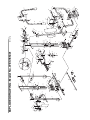
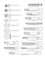
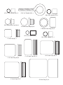
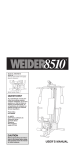
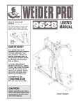
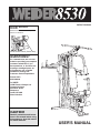
PATENT PENDING
Model No. WESY85301
Serial No.
Write the serial number in the space
above for reference.
Serial Number Decal (Under Seat)
QUESTIONS?
As a manufacturer, we are committed to providing you complete
customer satisfaction. If you
have questions, or find there are
missing or damaged parts, we
will guarantee you complete
satisfaction through our
Customer Service Department.
Please CALL:
0345-089009
Or WRITE:
ICON Fitness Lifestyle Ltd.
Greenwich House
223 North Street
Sheepscar
Leeds LS7 2AA
West Yorkshire
CAUTION!
Read all precautions and instructions in this manual before using
this equipment. Save this manual
for future reference.
USER'S MANUAL
TABLE OF CONTENTS
IMPORTANT PRECAUTIONS . . . . . . . . . . . . . . . . . . . . . . . . . . . . . . . . . . . . . . . . . . . . . . . . . . . . . . . . . . . . .2
BEFORE YOU BEGIN . . . . . . . . . . . . . . . . . . . . . . . . . . . . . . . . . . . . . . . . . . . . . . . . . . . . . . . . . . . . . . . . . . .3
ASSEMBLY . . . . . . . . . . . . . . . . . . . . . . . . . . . . . . . . . . . . . . . . . . . . . . . . . . . . . . . . . . . . . . . . . . . . . . . . . . .4
HOW TO USE THE HOME GYM SYSTEM . . . . . . . . . . . . . . . . . . . . . . . . . . . . . . . . . . . . . . . . . . . . . . . . . . .16
TROUBLE-SHOOTING AND MAINTENANCE . . . . . . . . . . . . . . . . . . . . . . . . . . . . . . . . . . . . . . . . . . . . . . . .18
CABLE DIAGRAM . . . . . . . . . . . . . . . . . . . . . . . . . . . . . . . . . . . . . . . . . . . . . . . . . . . . . . . . . . . . . . . . . . . . .19
ORDERING REPLACEMENT PARTS . . . . . . . . . . . . . . . . . . . . . . . . . . . . . . . . . . . . . . . . . . . . . . . .Back Cover
Note: A PART IDENTIFICATION CHART and a PART LIST/EXPLODED DRAWING are attached to the centre of
this manual. Remove the PART IDENTIFICATION CHART and the PART LIST/EXPLODED DRAWING before
beginning assembly.
IMPORTANT PRECAUTIONS
WARNING: To reduce the risk of serious injury, read the following important precautions before
using the home gym system.
9. Keep hands and feet away from moving
parts.
1. Read all instructions in this manual and in
the accompanying literature before using the
home gym system.
10. Keep your hands away from the squat arm
upright when the squat arm is being used.
Your hand could become pinched between
the squat arm upright and squat arm.
2. Use the home gym system only on a level
surface. Cover the floor beneath the home
gym system for protection.
11. Inspect all cables before each use. Make
sure that the cables remain on the pulleys at
all times. If the cables bind while you are
exercising, stop immediately and make sure
that the cables are on all of the pulleys.
Replace all cables every two years.
3. Inspect and tighten all parts often. Replace
any worn parts immediately.
4. Keep children under 12 and pets away from
the home gym system at all times.
5. Never release the press arm, butterfly arms,
squat arm, leg lever, lat bar or nylon strap
while weights are raised. The weights will fall
with great force.
12. Always disconnect the lat bar from the home
gym system when performing an exercise
that does not use the lat bar.
6. Do not use the VKR station when either
weight stack is in use.
13. If you feel pain or dizziness at any time while
exercising, stop immediately and begin cooling down.
7. Always wear athletic shoes for foot
protection.
8. Always stand on a foot plate when performing an exercise that could cause the home
gym system to tip.
WARNING: Before beginning this or any exercise program, consult your physician. This is especially
important for persons over the age of 35 or persons with pre-existing health problems. Read all
instructions before using. ICON assumes no responsibility for personal injury or property damage
sustained by or through the use of this product.
2
BEFORE YOU BEGIN
Thank you for selecting the versatile WEIDER¨ 8530
Home Gym System. The WEIDER¨ 8530 offers a
selection of weight stations designed to develop every
major muscle group of the body. Whether your goal is
to tone your body, build dramatic muscle size and
strength, or improve your cardiovascular system, the
WEIDER¨ 8530 will help you to achieve the specific
results you want.
have additional questions, please call our Customer
Service Department at 0345-089009. To help us assist
you, please note the product model number and serial
number before calling. The model number is
WESY85301. The serial number can be found on a
decal attached to the WEIDER¨ 8530 (see the front
cover of this manual).
Before reading further, please review the drawing
below and familiarise yourself with the parts that are
labelled.
For your benefit, read this manual carefully before
using the WEIDER¨ 8530 Home Gym System. If you
ASSEMBLED
DIMENSIONS:
Height: 74 in.
Width: 60 in.
Length: 54 in.
Lat Bar
High Pulley Station
Butterfly Arms
Squat Arm
VKR Arms
Backrest
Press Arm
Weight Stacks
Leg Lever
Weight Pin
Low Pulley Station
Foot Plate
3
ASSEMBLY
Before beginning assembly, carefully read the
following information and instructions:
¥ As you assemble the WEIDER 8530, be sure that
all parts are oriented as shown in the drawings.
¥ Place all parts of the WEIDER 8530 in a cleared
area and remove the packing materials; do not
dispose of the packing materials until assembly is
completed.
¥ Tighten all parts as you assemble them, unless
instructed to do otherwise.
THE FOLLOWING TOOLS (NOT INCLUDED) ARE
REQUIRED FOR ASSEMBLY:
¥ The assembly is broken into five stages: 1) frame
assembly, 2) press and butterfly arm assembly,
3) cable and pulley assembly, 4) seat and backrest assembly, and 5) VKR assembly. The hardware for each stage is packaged separately.
¥ Two (2) adjustable wrenches
¥ One (1) standard screwdriver
¥ One (1) phillips screwdriver
¥ Wait until you begin each assembly stage to open
the parts bag labelled for that assembly stage.
¥ One (1) rubber mallet
¥ Lubricant, such as grease or petroleum jelly,
and soapy water will also be needed.
¥ For help identifying the small parts used in
assembly, use the PART IDENTIFICATION
CHART located in the centre of this manual.
Note: Some small parts may have been preattached for shipping. If a part is not in the parts
bag, check to see if it has been pre-attached.
Assembly will be more convenient if you have the
following tools: A socket set, a set of open-end or
closed-end wrenches, or a set of ratchet wrenches.
1. Before beginning assembly, be sure that
you have read and understand the information in the box above.
1
56
FRAME ASSEMBLY
Press a 2Ó Inner Cap (27) into the indicated
end of the Stabiliser (5). Press 2Ó Outer
Caps (51) onto the other two locations on
the Stabiliser. Press a 2Ó Inner Cap (27) into
the end of the Base (4).
Insert four 5/16Ó x 2 1/2Ó Carriage Bolts (1)
up through the Stabiliser (5).
High
Side
74
Attach the Base (4) to the Stabiliser (5) with
two 5/16Ó x 2 3/4Ó Bolts (11), two 5/16Ó Flat
Washers (8), and two 5/16Ó Nylon Locknuts
(3). Do not tighten the Nylon Locknuts
yet.
3
27
11
51
Slide the VKR Upright (74) and the Squat
Arm Upright (56) onto the 5/16Ó x 2 1/2Ó
Carriage Bolts (1) in the Stabiliser (5). The
high side of the brackets on the VKR
Upright and Squat Arm Upright should be
on the side shown. Hand-tighten four 5/16Ó
Nylon Locknuts (3) onto the Carriage Bolts.
Do not tighten the Nylon Locknuts yet.
8
3
5
1
27
1
51
4
4
3
2. Insert two 5/16Ó x 2 1/2Ó Carriage Bolts (1) up
through the Base (4).
2
27
Slide the Front Upright (42) onto the 5/16Ó x
2 1/2Ó Carriage Bolts (1) in the Base (4).
Hand-tighten a 5/16Ó Nylon Locknut (3) onto
each Carriage Bolt. Do not tighten the
Nylon Locknuts yet.
27
56
Press a 1Ó Inner Cap (6) into the Front
Upright (42). Press a 2Ó Inner Cap (27) into
the Squat Upright (56). Press a 2Ó Inner Cap
into the VKR Upright (74).
74
42
6
3
FRAME ASSEMBLY
4
1
3. Press a 2Ó Inner Cap (27) into the end of the
Top Frame (55). Press a 1 3/4Ó Inner Cap
(44) into each end of the crossbar on the Top
Frame. Press two 1Ó Round Inner Caps (49)
into the top of the crossbar.
3
11
55
3
49
8
27
Attach the Top Frame (55) to the Front
Upright (42) with two 5/16Ó x 2 3/4Ó Bolts (11),
two 5/16Ó Flat Washers (8), and two 5/16Ó
Nylon Locknuts (3).
44
Crossbar
44
Attach the Top Frame (55) to the VKR Upright
(74) and the Squat Upright (56) with two 5/16Ó
x 2 3/4Ó Bolts (11) and two 5/16Ó Nylon
Locknuts (3).
11
3
56
42
74
Tighten all Locknuts used in steps 1Ð3.
4. Set two Weight Bumpers (19) on the bracket
on the Base (4) as shown. Set two Weight
Bumpers (19) on the bracket on the Stabiliser
(5).
4
Pin
Grooves
25
Stack eight Weights (25) on each set of
Weight Bumpers (19). Be sure that the pin
grooves are all on the same side of each
stack of Weights.
25
Pin
Grooves
19
Be careful not to tip either stack of
Weights (25) until step 6 is complete.
19
5ÑBracket
4ÑBracket
5
5. Press a Weight Tube Bumper (64) into the
end of a Weight Tube (63). Insert the Weight
Tube into the front stack of Weights (25). Be
sure that the pins on the Weight Tube are
sitting in the pin grooves in the top
Weight.
5
Holes
62
Lubricate the inside of the holes in a Top
Weight (65). Set the Top Weight onto the front
stack of Weights (25). Insert both Long
Weight Guides (62) into the stack of Weights.
Be sure that the holes in the Weight
Guides are at the top, as shown.
65
Lubricate
Pin
63
64
FRAME ASSEMBLY
25
6. Press a Weight Tube Bumper (64) into the
end of the other Weight Tube (63). Insert the
Weight Tube into the rear stack of Weights
(25). Be sure that the pins on the Weight
Tube are sitting in the pin grooves in the
top Weight.
6
Holes
73
Lubricate the inside of the holes in the other
Top Weight (65). Set the Top Weight onto the
rear stack of Weights (25). Insert both Short
Weight Guides (73) into the stack of Weights.
Be sure that the holes in the Weight
Guides are at the top, as shown.
Lubricate
65
Pin
63
64
25
6
FRAME ASSEMBLY
7. Attach the upper ends of the Long Weight
Guides (62) to the Top Frame (55) with a
5/16Ó x 6Ó Bolt (60), two 1/2Ó x 3/4Ó Spacers
(61), and a Nylon Locknut (3).
7
3
61
61
3
55
Be sure that the Pulley Bracket (20) is in
front of the right Long Weight Guide (62)
as shown.
60
60
Attach the upper ends of the Short Weight
Guides (73) to the Top Frame (55) with a
5/16Ó x 6Ó Bolt (60), two 1/2Ó x 3/4Ó Spacers
(61), and a Nylon Locknut (3).
20
73
8. Press a 1Ó x 7/8Ó Plastic Bushing (90) onto
each welded spacer on the Press Frame (17).
Slide the Press Frame into place onto the
Base (4). Note: This will be a tight fit. The
Plastic Bushings should fit on each end of
the indicated tube in the Base. Make sure
that the pulleys are on the side shown.
62
8
59
17
Lubricate the 3/8Ó x 8Ó Bolt (59). Attach the
Press Frame (17) to the Base (4) with the
3/8Ó x 8Ó Bolt and a 3/8Ó Nylon Locknut (21).
Lubricate
Welded
Spacers
4ÑTube
ARM ASSEMBLY
21
9. Wet the handle of one Press Arm (46) with
soapy water. Slide a 5Ó Plastic Grip (83) onto
the handle. Press a 1Ó Round Inner Cap (49)
into the other end of the handle. Press a
1 3/4Ó Inner Cap (44) into the Press Arm.
90
44
9
49
83
Handle
Attach the Press Arm (46) to one side of the
Press Frame (17) with two 5/16Ó x 2 1/2Ó
Bolts (22) and two 5/16Ó Nylon Locknuts (3).
46
22
Assemble the other Press Arm (46) in the
same manner.
3
46
17
10. Identify the Right Arm (48) and the Left Arm
(47). Note the position of the welded bracket
on each Arm. Arm identification is very
important for step 11.
10
86
31
50
31
Attach a ÒVÓ-Pulley (50) and a Long Cable
Trap (31) to the Right Arm (48) with a 3/8Ó x
2 1/2Ó Bolt (86) and a 3/8Ó Nylon Locknut
(21).
Welded
Bracket
50
47
21
Attach a ÒVÓ-Pulley (50) and a Long Cable
Trap (31) to the Left Arm (47) in the same
manner.
48
7
11. Lubricate both axles on the Top Frame (55).
11
55
Slide the Right Arm (48) onto the right axle.
Be careful not to confuse the Right Arm
with the Left Arm (47); note the position of
the ÒVÓ Pulley (50) to identify the Right
Arm. Be sure that the upper end of the
Right Arm is behind the indicated bracket
on the Top Frame (55).
Bracket
47
AxleÑ
Lubricate
50
Tap two 1Ó Retainers (69) and a 1Ó Round
Cover Cap (70) onto the axle. Be sure that
the teeth on the Retainers bend toward the
Round Cover Cap, as shown in the inset
drawing.
69
70
45
44
48
Attach the Left Arm (47) in the same manner.
Press 1 3/4Ó Inner Caps (44) into the lower
ends of the Right and Left Arms (47, 48). Wet
the lower end of each Arm with soapy water.
Slide a 10Ó Pad (45) onto the lower end of
each Arm.
44
45
55ÑAxle
ARM ASSEMBLY
69
70
12. Press two 1Ó x 2Ó Inner Caps (87) into the
indicated end of the Squat Arm (84).
12
83
Attach the Squat Arm (84) to the VKR Upright
(74) with a 3/8Ó x 5 1/2Ó Bolt (93) and a 3/8Ó
Nylon Locknut (21). Be sure that the indicated bracket is pointing down as shown.
22
85
82
87
49
8
82
91
Wet the ends of the Squat Arm (84) with
soapy water. Slide the two Squat Arm Pads
(85) onto the Squat Arm.
3
85
84
Attach a Handle (82) to one side of the Squat
Arm (84) with a 5/16Ó x 2 1/2Ó Bolt (22), two
5/16Ó Flat Washers (8), a 1/2Ó x 17/32Ó Spacer
(91), and a 5/16Ó Nylon Locknut (3).
21
Bracket
93
Wet the Handle (82) with soapy water. Slide a
5Ó Plastic Grip (83) onto the Handle. Press a
1Ó Round Inner Cap (49) into the other end of
the Handle.
Assemble another Handle (82) to the other
side of the Squat Arm (84) in the same manner.
8
74
During steps 13 to 25, refer to the CABLE DIAGRAM on page 19 of this manual. Identify the
three cables by their lengths, and note the
positions of the cable traps. IMPORTANT: Do
not overtighten the bolts and nuts securing
the pulleys. The pulleys must turn freely.
13
13. Locate the Medium Cable (58). Route the
Medium Cable around the indicated 3 1/2Ó
Pulley (15) attached to the Top Frame (55).
Be sure that the ball is on the indicated
side of the Pulley and that the Cable is
between the Pulley and the hook. Tighten
the 3/8Ó x 3 3/4Ó Bolt (88) and the 3/8Ó Nylon
Locknut (not shown).
15
Ball
88
Hook
14
14. Wrap the Medium Cable (58) around a ÒVÓPulley (50). Attach the ÒVÓ-Pulley and a Long
Cable Trap (31) to the indicated bracket on
the Front Upright (42) with a 3/8Ó x 2 1/2Ó Bolt
(86) and a 3/8Ó Nylon Locknut (21). Be sure
that the Long Cable Trap is positioned to
hold the Cable in place.
CABLE ASSEMBLY
58
55
86
58
31
31
50
86
Bracket
21
Route the Medium Cable (58) around the ÒVÓPulley (50) on the Left Arm (47). Be sure that
the Cable is in the groove of the Pulley and
that the Long Cable Trap (31) holds the
Cable in place. Tighten the 3/8Ó x 2 1/2Ó Bolt
(86) and the 3/8Ó Nylon Locknut (not shown).
42
50
47
15. Route the Medium Cable (58) around the ÒVÓPulley (50) on the Right Arm (48). Be sure
that the Cable is in the groove of the ÒVÓPulley and that the Long Cable Trap (31) is
positioned to hold the Cable in place.
Tighten the 3/8Ó x 2 1/2Ó Bolt (86) and the 3/8Ó
Nylon Locknut (not shown).
15
68
31
86 50
20
66
Route the Medium Cable (58) around the
3 1/2Ó Pulley (15) attached to the Pulley
Bracket (20). Be sure that the Cable is in
the groove of the Pulley and that the Cable
Trap (66) holds the Cable in place. Tighten
the 3/8Ó Nylon Locknut (21) and the 3/8Ó x 2Ó
Bolt (not shown). Tighten the 5/16" x 5Ó Bolt
(68) and the 5/16" Nylon Locknut (not shown).
Be sure that the Pulley Bracket swivels freely.
48
21
15
58
16
16. See the inset drawing. Attach a 3 1/2Ó Pulley
(15) and a Cable Trap (66) to the upper hole
in the Long ÒUÓ-Bracket (57) with a 3/8Ó x 2Ó
Bolt (12) and a 3/8Ó Nylon Locknut (21). Be
sure that the Cable Trap is inside the Long
ÒUÓ-Bracket. (Note: This may come preassembled.)
15
58
58
15
57
66
Route the Medium Cable (58) through the
3 1/2Ó Pulley (15) and Long ÒUÓ-Bracket (57)
shown in the inset drawing. Be sure that the
Cable is in the groove of the Pulley and
that the Cable and Pulley move smoothly.
21
12
57
9
17. Route the Medium Cable (58) around the
3 1/2Ó Pulley (15) attached to the bracket on
the Top Frame (55). Tighten the 3/8Ó x 2Ó Bolt
(12) and the 3/8Ó Nylon Locknut (21). (Note:
This Pulley is pre-assembled. It has been
shown disassembled for easy part identification.) Be sure that the Cable is in the
groove of the Pulley and that the Cable
and Pulley move smoothly.
CABLE ASSEMBLY
18. Remove the indicated 3 1/2Ó Low Pulley (95)
from the Press Frame (17). Reattach the
Pulley with the 5/8Ó x 9/16Ó Spacer (7)
between the Pulley and the Press Frame.
Finger tighten the 3/8Ó Nylon Locknut (21).
17
Bracket
58
21
18
Locate the Short Cable (23). Route the
Short Cable under the 3 1/2Ó Low Pulley (95)
attached to the lower hole in the Press Frame
(17). Be sure that the end of the Cable with
the ball is on the indicated side of the
Press Frame and that the Cable is between
the Pulley and the crossbar on the Press
Frame. Tighten the 3/8Ó Nylon Locknut (21)
and 3/8Ó x 3 3/4Ó Bolt (88).
Route the Short Cable (23) around the 3 1/2Ó
Pulley (15) attached to the lower hole in the
Front Upright (42). Be sure that the Cable
Trap (not shown) is turned to hold the
Cable in place and that the Cable is routed
around the Pulley as shown. Tighten the
3/8Ó Nylon Locknut (21) and 3/8Ó x 3 3/4Ó Bolt
(not shown).
23 9
15
88
21
Ball
42
Crossbar 21
17
19
15
23
15
21
21
19. Route the Short Cable (23) around the 3 1/2Ó
Pulley (15) attached to the upper hole in the
Press Frame (17). Be sure that the Cable
Trap (66) is in the Ò3 oÕclockÓ position and
that the Cable is routed around the Pulley
as shown. Tighten the 3/8Ó Nylon Locknut
(21) and 3/8Ó x 3 1/2Ó Bolt (not shown).
Route the Short Cable (23) around the 3 1/2Ó
Pulley (15) attached to the upper hole in the
Front Upright (42). Be sure that the Cable
Trap (not shown) is turned to hold the
Cable in place and that the Cable is routed
around the Pulley as shown. Tighten the
3/8Ó Nylon Locknut (21) and 3/8Ó x 3 3/4Ó Bolt
(not shown).
20. Attach the end of the Short Cable (23) to the
Long ÒUÓ-Bracket (57) with a 1/4Ó Nylon
Locknut (2) and a 1/4Ó Flat Washer (10). Do
not tighten the 1/4Ó Nylon Locknut. It
should be threaded onto the Cable only a
couple of turns.
66
12
3
9
42
6
17
20
2
57
10
23
10
12
15
55
7
15
21. Attach the Medium Cable (58) to a Small ÒUÓBracket (71) with a 1/4Ó Nylon Locknut (2)
and a 1/4Ó Flat Washer (10). Do not tighten
the 1/4Ó Nylon Locknut. It should be
threaded onto the Cable only a couple of
turns.
21
Attach the Small ÒUÓ-Bracket (71) to the indicated Weight Tube (63) with a 5/16Ó x 1 3/4Ó
Bolt (24) and a 5/16Ó Nylon Locknut (3).
58
71
24
3
63
CABLE ASSEMBLY
10
2
22. Locate the Long Cable (72). Attach the Long
Cable (72) to the other Small ÒUÓ-Bracket (71)
with a 1/4Ó Nylon Locknut (2) and a 1/4Ó Flat
Washer (10). Do not tighten the 1/4Ó Nylon
Locknut. It should be threaded onto the
Cable only a couple of turns.
22
Attach the Small ÒUÓ-Bracket (71) to the indicated Weight Tube (63) with a 5/16Ó x 1 3/4Ó
Bolt (24) and a 5/16Ó Nylon Locknut (3).
3
72
71
24
63
10
2
11
23. Route the Long Cable (72) around the 3 1/2Ó
Pulley (15) on the Top Frame (55). Tighten
the Nylon Locknut (21) and the 3/8Ó x 2Ó Bolt
(not shown).
23
55
15
21
See inset drawing. Wrap the Long Cable (72)
around a 3 1/2Ó Pulley (15). Attach the Pulley
and a Cable Trap (66) to the bracket on the
Stabiliser (5) with a 3/8Ó x 2Ó Bolt (12) and a
3/8Ó Nylon Locknut (21). Be sure that the
Cable Trap is turned to hold the Cable in
place.
72
12
72
66
15
5
CABLE ASSEMBLY
21
15
5
21
24. Wrap the Long Cable (72) around a 3 1/2Ó
Pulley (15). Attach the Pulley and a Cable
Trap (66) to the Squat Arm (84) with the 3/8Ó
x 2 1/4Ó Bolt (94) and a 3/8Ó Jam Nut (92). Be
sure that the 3/8Ó Jam Nut is on the side
shown and that the Cable Trap is positioned to hold the Cable in place.
24
66
15
94
84
92
Bracket
72
12
CABLE ASSEMBLY
25. See inset drawing A. Note: The inset drawing shows the view from the other side of
the Squat Arm Upright (56). Wrap the Long
Cable (72) around a ÒVÓ-Pulley (50). Attach
the ÒVÓ-Pulley and a Long Cable Trap (31) to
the top hole in the Squat Arm Upright with the
3/8Ó x 5Ó Bolt (67), the 5/8Ó x 3/8Ó Spacer (76),
a 3/8Ó Flat Washer (9), and a 3/8Ó Nylon
Locknut (21). Position the Long Cable Trap
(31) as shown.
25
Insets show view
from other side
A
21
9
72
67
76
See inset drawing B. Note: The inset drawing shows the view from the other side of
the Squat Arm Upright (56). Slide the end of
the Long Cable (72) onto the end of the 3/8Ó x
2 1/4Ó Bolt (94). Thread another 3/8Ó Jam Nut
(92) onto the Bolt. Do not tighten the second Jam Nut. There must be room
between the two Jam Nuts for the end of
the Cable to pivot.
26. Attach the Backrest (41) to the Front Upright
(42) with two 1/4Ó x 2 1/2Ó Screws (43) and
two 1/4Ó Flat Washers (10).
50
72
50
31
56
B
92
94
72
26
42
41
SEAT ASSEMBLY
43 10
27. Press a 1 1/2Ó Inner Cap (32) into the Seat
Frame (36).
27
13
Insert a 1/4Ó x 2Ó Carriage Bolt (38) through
the centre hole in the Seat Plate (37). Attach
the Seat Plate to the Seat (13) with two 1/4Ó x
1/2Ó Screws (18).
38
37
Insert the 1/4Ó x 2Ó Carriage Bolt (38) through
the indicated hole in the Seat Frame (36).
Tighten a 1/4Ó Nylon Locknut (2) with a 1/4Ó
Flat Washer (10) onto the Carriage Bolt.
18
36
Attach the other end of the Seat (13) to the
Seat Frame (36) with a 1/4Ó Flat Washer (10)
and a 1/4Ó x 2Ó Machine Screw (81).
13
81
10
2
32
28. Press a 1 1/2Ó Inner Cap (32) into the Leg
Lever (29).
28
Lubricate the 5/16Ó x 2 1/4Ó Bolt (33). Attach
the Leg Lever (29) to the Seat Frame (36)
with the 5/16Ó x 2 1/4Ó Bolt and a 5/16Ó Nylon
Locknut (3).
36
3
33ÑLubricate
29
Insert the 5/16Ó x 2Ó Eyebolt (35) into the Leg
Lever (29) from the direction shown. Tighten
a 5/16Ó Nylon Locknut (3) with a 5/16Ó Flat
Washer (8) onto the Eyebolt.
8
35
3
SEAT ASSEMBLY
32
29. Rest the Seat Frame (36) on the indicated pin
in the Front Upright (42). Attach the Seat
Frame to the Front Upright with a 5/16Ó x
2 3/4Ó Carriage Bolt (14) and the Seat Knob
(40).
29
42
40
36
14
Pin
30. Press two 3/4Ó Round Inner Caps (34) into
each 13 1/2Ó Pad Tube (28).
30
34
36
Insert the 13 1/2Ó Pad Tube (28) into the Seat
Frame (36). Slide a 6Ó Pad (30) onto each
end of the Pad Tube.
30
28
Insert the other 13 1/2Ó Pad Tube (28) into the
Leg Lever (29). Slide a 6Ó Foam Pad (30)
onto each end of the Pad Tube.
30
34
29
VKR ASSEMBLY
31. Press 1 1/2Ó Inner Caps (32) into the ends of
the Left VKR Arm (79) and the Right VKR
Arm (80).
31
74
75
Attach the Left VKR Arm (79) and the Right
VKR Arm (80) to the VKR Upright (74) with
two 5/16Ó x 3Ó Bolts (75) and two 5/16Ó Nylon
Locknuts (3).
79
80
32
14
3
32. Wet the handle on the Right VKR Arm (80)
with soapy water. Slide a 5Ó Plastic Grip (83)
onto the Handle. Press a 1Ó Round Inner Cap
(49) into the bottom of the handle.
32
83
Attach a 5Ó Plastic Grip (83) and a 1Ó Round
Inner Cap (49) to the handle on the Left VKR
Arm (79) in the same manner.
79
VKR ASSEMBLY
80
49
83
33. Attach a VKR Armrest (78) to the Right VKR
Arm (80) with two 1/4Ó x 2Ó Machine Screws
(81) and two 1/4Ó Flat Washers (10).
33
78
80
74
Attach a VKR Armrest (78) to the Left VKR
Arm (79) in the same manner.
10
Attach the VKR Backrest (77) to the VKR
Upright (74) with two 1/4Ó x 2 1/2Ó Screws
(43) and two 1/4Ó Flat Washers (10).
43
10
79
81
78
77
DECALS
34. Remove the decals from the Decal Sheet (not
shown) and apply them to the home gym system in the locations shown:
A Ñ8530
B ÑHIGH PULLEY
CÑBUTTERFLY
DÑMILITARY PRESS
E ÑSQUAT STATION
F ÑBENCH PRESS
GÑLEG DEVELOPER
HÑLOW PULLEY
I ÑVKR
Make sure that all parts have been properly tightened. Use of the remaining parts will be explained
in HOW TO USE THE HOME GYM SYSTEM,
beginning on page 16 of this manual.
Before using the home gym system, pull each
cable a few times to be sure that the cables move
smoothly over the pulleys. If one of the cables
does not move smoothly, find and correct the
problem. IMPORTANT: If the cables are not
properly installed, they may be damaged when
heavy weight is used. See the CABLE DIAGRAM on page 19 of this manual for proper
cable routing. If there is any slack in the
cables, the cables should be tightened. See
TROUBLE-SHOOTING AND MAINTENANCE on
page 18.
15
34
B
A
C
D
E
I
F
G
H
HOW TO USE THE HOME GYM SYSTEM
The instructions below describe how each part of the home gym system can be adjusted. Refer to the exercise
poster accompanying this manual to see how the home gym system should be set up for each exercise.
IMPORTANT: When attaching the lat bar or nylon strap, make sure that the attachments are in the correct starting position for the exercise to be performed. If there is any slack in the cables or chain as an
exercise is performed, the effectiveness of the exercise will be reduced.
CHANGING THE WEIGHT SETTING
The WEIDER 8530 features two weight stacks. The
front weight stack is connected to the upper and
lower pulleys, the press arm, and the butterfly arms.
The rear weight stack is connected to the squat arm.
26
To change the weight setting of either weight stack,
insert a Weight Pin (26) under the desired Weight
(25). Insert the Weight Pin until the bent end of the
Weight Pin is touching the Weights, and turn the bent
end downward. The weight setting of either weight
stack can be changed from 6.5 pounds to 106.5
pounds, in increments of 12.5 pounds. Note: Due to
the cables and pulleys, the actual amount of
resistance at each exercise station may vary from
the weight setting. Use the WEIGHT RESISTANCE
CHART on page 17 to find the actual amount of
resistance at each weight station.
25
25
26
ATTACHING THE LAT BAR OR NYLON STRAP TO
THE HIGH PULLEY STATION
53
Attach the Lat Bar (54) to the Medium Cable (58) with
a Cable Clip (53). For some exercises, the Chain (52)
should be attached between the Lat Bar and the
Medium Cable with two Cable Clips. Adjust the
length of the Chain between the Lat Bar and the
Medium Cable so the Lat Bar is in the correct
starting position for the exercise to be performed.
52
58
53
54
The Nylon Strap (39) can be attached in the same
manner.
39
ATTACHING THE LAT BAR OR NYLON STRAP TO
THE LOW PULLEY STATION
23
53
Attach the Lat Bar (54) to the Short Cable (23) with a
Cable Clip (53). For some exercises, the Chain (52)
should be attached between the Lat Bar and the
Short Cable with two Cable Clips. Adjust the length
of the Chain between the Lat Bar and the Short
Cable so the Lat Bar is in the correct starting
position for the exercise to be performed.
52
53
39
54
The Nylon Strap (39) can be attached in the same
manner.
16
ATTACHING AND REMOVING THE SEAT
40
36
To attach the Seat (13), set the bracket on the Seat
Frame (36) onto the indicated pins on the Front
Upright (42). Attach the Seat Frame to the Front
Upright with the 5/16Ó x 2 3/4Ó Carriage Bolt (14) and
the Seat Knob (40).
13
42
For some exercises, the Seat (13) must be removed.
First, be sure that the chain is not attached to the leg
lever. Next, remove the Seat Knob (40) and the 5/16Ó
x 2 3/4Ó Carriage Bolt (14) from the Seat Frame (36).
Lift the Seat Frame off the Front Upright (42).
14
ATTACHING THE LEG LEVER TO THE LOW
PULLEY STATION
To use the Leg Lever (29), the seat must be attached
to the front upright (see ATTACHING AND REMOVING THE SEAT above.)
53
Attach one end of the Chain (52) to the Short Cable
(23) with a Cable Clip (53). Attach the other end of
the Chain to the Eyebolt (35) with a Cable Clip.
52
29
35
53
23
WEIGHT RESISTANCE CHART
This chart shows the approximate weight resistance at each station. ÒTopÓ refers to the 6.5 lbs. top weight. The
other numbers refer to the 12.5 lbs. weight plates. The butterfly arm resistance listed is the resistance for each
butterfly arm. Note: The actual resistance at each weight station may vary due to differences in individual weight
plates, as well as friction between the cables, pulleys, and weight guides.
WEIGHT
PLATES
PRESS ARM
BUTTERFLY ARM
LEG LEVER
HIGH PULLEY
LOW PULLEY
SQUAT ARM
(lbs.)
(lbs.)
(lbs.)
(lbs.)
(lbs.)
(lbs.)
Top
20
10
15
14
24
31
1
45
22
36
28
54
52
2
70
33
54
44
82
75
3
99
42
75
60
115
101
4
128
48
96
72
147
114
5
153
60
115
90
175
136
6
184
69
137
103
209
157
7
204
79
146
126
223
174
8
247
91
176
138
269
194
17
TROUBLE-SHOOTING AND MAINTENANCE
Inspect and tighten all parts each time you use the home gym system. Replace any worn parts immediately. The
home gym system can be cleaned using a damp cloth and mild non-abrasive detergent. Do not use solvents.
TIGHTENING THE CABLES
Woven cable, the type of cable used on the home gym system, can stretch slightly when it is first used. If there
is slack in the cables before resistance is felt, the cables should be tightened.
Tightening the Medium and Short Cables
If any slack is felt when using the front weight stack, both
the Medium Cable (58) and the Short Cable (23) will need
to be tightened. Insert the weight pin into the middle of the
weight stack. Slack can be removed from these cables
three ways:
¥
1
58
See drawing 1. Tighten the 1/4Ó Nylon Locknut (2) that
connects the end of the Short Cable (23) to the Long
ÒUÓ-Bracket (57).
66
21
¥
¥
See drawing 1. Move the 3 1/2Ó Pulley (15) to the other
hole in the Long ÒUÓ-Bracket (57). Remove the 3/8Ó
Nylon Locknut (21) and the 3/8Ó x 2Ó Bolt (12) from the
Cable Trap (66), Pulley, and Long ÒUÓ-Bracket. Reattach the Pulley and Cable Trap. Be sure that the
Cable Trap is in the proper position and that the Cable
and Pulley move smoothly.
2
12
23
72
See drawing 2. Tighten the 1/4Ó Nylon Locknut (2) that
connects the end of the Medium Cable (58) to the
Small ÒUÓ-Bracket (71).
58
71
2
71
If any slack is felt when using the rear weight stack, the
Long Cable (72) will need to be tightened. Insert the weight
pin into the middle of the weight stack. Slack can be
removed from these cables two ways:
¥
57
2
Tightening the Long Cable
¥
15
See drawing 2. Tighten the 1/4Ó Nylon Locknut (2) that
connects the end of the Long Cable (72) to the Small
ÒUÓ-Bracket (71).
2
3
See drawing 3. Move the ÒVÓ-Pulley (50) to another
hole in the Squat Arm Upright (56). Remove the 3/8Ó
Nylon Locknut (21) and the 3/8Ó x 5Ó Bolt (not shown)
from the Long Cable Trap (not shown), and Pulley. Reattach the Pulley and Cable Trap. Be sure that the
Cable trap is in the proper position and that the Cable
and Pulley move smoothly.
56
Do not overtighten the cables. The top weight will be
lifted off the weight stack.
Note: Inspect all cables before each use. If a cable
tends to slip off the pulleys often, the cable may have
become twisted. Remove the cable and re-install it.
21
50
If the cables need to be replaced, see ORDERING REPLACEMENT PARTS on the back cover of this manual.
Replace all cables every two years.
18
CABLE DIAGRAM
The cable diagram below shows the proper routing of the Long Cable (72), the Medium Cable (58), and the
Short Cable (23). Use the diagram to be sure that the three cables and cable traps have been assembled correctly. If the cables have not been correctly routed, the home gym system will not function properly and damage
may occur. The insets show the proper positioning of the cable traps. The cable traps should be positioned so
that the cables will not come off the pulleys. Be sure that the cable traps do not touch or bind the cables.
1ÑHigh Pulley
2
3
7
2
5
4
Long Cable (72)
6
6ÑSquat Arm
Bracket
TOP VIEW
Medium
Cable (58)
5ÑLong ÒUÓ-Bracket
4
Short Cable (23)
5ÑThis side of Pulley
must be against the
Squat Arm Upright
4
3
1ÑRear Weight
Stack
8ÑFront Weight
Stack
3
2
1ÑLow Pulley
19
ORDERING REPLACEMENT PARTS
If you encounter any difficulties or problems with this product, contact the ICON Fitness Lifestyle Ltd. office, or
write:
ICON Fitness Lifestyle Ltd.
Greenwich House
223 North Street
Sheepscar
Leeds LS7 2AA
West Yorkshire
Tel: Country Code: 0345-089009
Fax: 0113-2411120
1. The MODEL NUMBER of the product (WESY85301).
2. The NAME of the product (WEIDER¨ 8530 Home Gym System).
3. The SERIAL NUMBER of the product (see the front cover of this manual).
4. The KEY NUMBER and DESCRIPTION of the part(s) (see the PART LIST and EXPLODED DRAWING
attached at the centre of this manual.)
Part No. 135761 R1197A WEIDER is a registered trademark of ICON Health & Fitness, Inc. © 1997 Printed in Canada
49
32
83
77
78
10
81
3
83
75
32
75
80
27
74
10
11
3
51
78
43
11
1
83
2
10
8
51
25
79
11
3
60
19
61
64
21
15
50
3
54
1
31
66
26
12
11 8
63
67
24
65
71
72
73
3
53
52
5
3
76
27
83
9
56
21
39
27
21
93
21
66
94
84
20
15
72
15
82
83
66
8
92
8
12
3
68
3
10
2
21
91 8
49
91
87
22
57
3
23
15
87
66
12
55
83
85
15
21
82
22
8
27
EXPLODED DRAWINGÑModel No. WESY85301
25
2
3
10
60
3
21
12
61
19
4
64
65
24
71
63
49
44
58
62
3
8
11
1
26
43
3
15
21
3
9
21
49 44
10
12
R1197A
42
21
50
88
86
3
27
15
31
15
49
6
66
14
41
58
44
46
88
81
66
36
40
83
34
21
37
30
33
18
17
21
22
34
35
2
13
70
30
10
38
45
44
48
69
89
50
31
86
3
32
8
29
32
70
90
21
30
34
45
44
9
59
15
95
7
88
44
47
16
46
34
30
66
3
28
3
83
28
69
89
23
49
PART LISTÑModel No. WESY85301
Key No.
Qty.
1
2
3
4
5
6
7
8
9
10
11
12
13
14
15
16
17
18
19
20
21
22
23
24
25
26
27
28
29
30
31
32
33
34
35
36
37
38
39
40
41
42
43
44
45
46
47
48
6
4
27
1
1
1
1
9
4
13
6
6
1
1
10
1
1
2
4
1
16
6
1
2
16
2
5
2
1
4
4
4
1
4
1
1
1
1
1
1
1
1
4
6
2
2
1
1
Description
5/16Ó x 2 1/2Ó Carriage Bolt
1/4Ó Nylon Locknut
5/16Ó Nylon Locknut
Base
Stabiliser
1Ó Inner Cap
5/8Ó x 9/16Ó Spacer
5/16Ó Flat Washer
3/8Ó Flat Washer
1/4Ó Flat Washer
5/16Ó x 2 3/4Ó Bolt
3/8Ó x 2Ó Bolt
Seat
5/16Ó x 2 3/4Ó Carriage Bolt
3 1/2Ó Pulley
3/8Ó x 3 1/2Ó Bolt
Press Frame
1/4Ó x 1/2Ó Screw
Weight Bumper
Pulley Bracket
3/8Ó Nylon Locknut
5/16Ó x 2 1/2Ó Bolt
Short Cable
5/16Ó x 1 3/4Ó Bolt
Weight
Weight Pin
2Ó Inner Cap
13 1/2Ó Pad Tube
Leg Lever
6Ó Pad
Long Cable Trap
1 1/2Ó Inner Cap
5/16Ó x 2 1/4Ó Bolt
3/4Ó Round Inner Cap
5/16Ó x 2Ó Eyebolt
Seat Frame
Seat Plate
1/4Ó x 2Ó Carriage Bolt
Nylon Strap
Seat Knob
Backrest
Front Upright
1/4Ó x 2 1/2Ó Screw
1 3/4Ó Inner Cap
10Ó Pad
Press Arm
Left Arm
Right Arm
R1197A
Key No.
Qty.
49
50
51
52
53
54
55
56
57
58
59
60
61
62
63
64
65
66
67
68
69
70
71
72
73
74
75
76
77
78
79
80
81
82
83
84
85
86
87
88
89
90
91
92
93
94
#
8
4
2
1
2
1
1
1
1
1
1
2
4
2
2
2
2
7
1
1
4
2
2
1
2
1
2
1
1
2
1
1
5
2
8
1
2
3
2
4
2
2
2
2
1
1
1
Description
1Ó Round Inner Cap
ÒVÓ-Pulley
2Ó Outer Cap
Chain
Cable Clip
Lat Bar
Top Frame
Squat Arm Upright
Long ÒUÓ-Bracket
Medium Cable
3/8Ó x 8Ó Bolt
5/16Ó x 6Ó Bolt
1/2Ó x 3/4Ó Spacer
Long Weight Guide
Weight Tube
Weight Tube Bumper
Top Weight
Cable Trap
3/8Ó x 5Ó Bolt
5/16Ó x 5Ó Bolt
1Ó Retainer
1Ó Round Cover Cap
Small ÒUÓ-Bracket
Long Cable
Short Weight Guide
VKR Upright
5/16Ó x 3Ó Bolt
5/8Ó x 3/8Ó Spacer
VKR Backrest
VKR Arm Rest
Left VKR Arm
Right VKR Arm
1/4Ó x 2Ó Machine Screw
Handle
5Ó Plastic Grip
Squat Arm
Squat Arm Pad
3/8Ó x 2 1/2Ó Bolt
1Ó x 2Ó Inner Cap
3/8Ó x 3 3/4Ó Bolt
1 1/4Ó x 2 1/2Ó Plastic Bushing
1Ó x 7/8Ó Plastic Bushing
1/2Ó x 17/32Ó Spacer
3/8Ó Jam Nut
3/8Ó x 5 1/2Ó Bolt
3/8Ó x 2 1/4Ó Bolt
UserÕs Manual
Note: Ò#Ó indicates a non-illustrated part. Specifications are subject to change without notice.
1/4" Nylon Locknut (2)Ð4
1/4" x 2" Machine Screw (81)Ð5
5/16" Nylon Locknut (3)Ð27
5/16" x 2 1/2" Bolt (22)Ð6
3/8" Nylon Locknut (21)Ð16
3/8" Jam Nut (92)Ð2
1/4" Flat Washer (10)Ð13
5/16" Flat Washer (8)Ð7
3/8" x 2" Bolt (12)Ð6
5/16" x 2 1/4" Bolt (33)Ð1
1/4" x 2 1/2" Screw (43)Ð4
5/16" x 2 1/2" Carriage Bolt (1)Ð6
3/8" x 2 1/2" Bolt (86)Ð3
3/8" Flat Washer (9)Ð4
5/16" x 2 3/4" Bolt (11)Ð6
3/8" x 1 3/4" Bolt (24)Ð2
1/4" x 2" Carriage Bolt (38)Ð1
5/16" x 2 3/4" Carriage Bolt (14)Ð1
5/16" x 3" Bolt (75)Ð2
3/8" x 5" Bolt (67)Ð1
1/2" x 17/32" Spacer (91)Ð2
5/16" x 2" Eyebolt (35)Ñ1
5/8" x 5/8" Spacer (76)Ð1
3/4" Round Inner Cap (34)Ð4
1" Round Inner Cap (49)Ð8
1" Round Cover Cap (70)Ð2
1/2" x 3/4" Spacer (61)Ð4
5/8" x 9/16" Spacer (7)Ð1
1" Inner Cap (6)Ð1
1" x 2" Inner Cap (87)Ð2
1 3/4" Inner Cap (44)Ð6
1 1/2" Inner Cap (32)Ð4
2" Inner Cap (27)Ð5
2" Outer Cap (51)Ð2