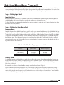
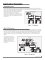
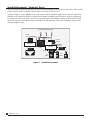
1
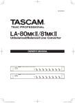
Contents
Introduction ................................................................................................................................1
Packing List............................................................................................................................................................................................ 1
Warranty ......................................................................................................................................1
One Year limited Warranty on MaxxBass Hardware........................................................................................................................... 1
Warranty Service ................................................................................................................................................................................... 2
Trade Marks ........................................................................................................................................................................................... 2
Copyright............................................................................................................................................................................................... 2
Waves contact Info ................................................................................................................................................................................ 2
North and South America:............................................................................................................................................................. 2
Rest of the world: ........................................................................................................................................................................... 2
MaxxBass Overview ....................................................................................................................3
MaxxBass System Overview.................................................................................................................................................................. 3
MaxxBass Technology ........................................................................................................................................................................... 3
Front Panel Features.............................................................................................................................................................................. 4
Rear panel Features ............................................................................................................................................................................... 4
External Power Supply .......................................................................................................................................................................... 5
Setting MaxxBass Controls.........................................................................................................7
Step 1: Setting input level ..................................................................................................................................................................... 7
Input Trim Knob ............................................................................................................................................................................ 7
Step 2: Setting the MaxxBass effect ...................................................................................................................................................... 7
Frequency Knob ............................................................................................................................................................................. 7
Intensity Knob ................................................................................................................................................................................ 7
Step 3: Verifying the settings and Locking........................................................................................................................................... 8
Bypass.............................................................................................................................................................................................. 8
Lock................................................................................................................................................................................................. 8
Application Examples .................................................................................................................9
Small Speaker Systems .......................................................................................................................................................................... 9
Clubs, DJ, Band Systems ....................................................................................................................................................................... 9
Sound Reinforcement - Subwoofer Arrays ........................................................................................................................................ 10
Specifications.............................................................................................................................11
Technical Specifications ...................................................................................................................................................................... 11
Architectural Specifications ................................................................................................................................................................ 11
Architectural Specifications for MaxxBass 101 .......................................................................................................................... 11
Architectural Specifications for MaxxBass 102 .......................................................................................................................... 12
MaxxBass User Guide
i
ii
MaxxBass User Guide
Introduction
Thank you for purchasing the Waves MaxxBass processor unit. This guide contains important information about how to
install and use the unit.
Packing List
The MaxxBass package should contains the following:
MaxxBass 101 or MaxxBass 102
16VAC Power Supply Unit
User Guide (this document)
Registration Card
If any items are missing, please contact your dealer.
Warranty
One Year limited Warranty on MaxxBass Hardware
KS.Waves Ltd. (“Waves”) warrants that the hardware contained herein shall conform in all material respects to the specifications contained in the product documentation for a period of one (1) year from the date of original purchase from Waves or
its authorized resellers. In the case of a valid warranty claim, your sole and exclusive remedy and Waves’s entire liability under
any theory of liability will be, at Waves’ sole discretion, to repair or replace the Product without charge or to refund the purchase price to you.
THIS WARRANTY IS IN LIEU OF ALL WARRANTIES, WHETHER ORAL OR WRITTEN, EXPRESS, IMPLIED OR
STATUTORY, WAVES MAKES NO OTHER WARRANTY, EITHER EXPRESS OR IMPLIED, INCLUDING, WITHOUT
LIMITATION, ANY IMPLIED WARRANTIES OF MERCHANTABILITY, FITNESS FOR A PARTICULAR PURPOSE, OR
NON-INFRINGEMENT, PURCHASER’S SOLE AND EXCLUSIVE REMEDY UNDER THIS WARRANTY SHALL BE REPAIR
OR REPLACEMENT AS SPECIFIED HEREIN.
This limited warranty, with all terms, conditions and disclaimers set forth herein, shall extend to the original purchaser and
anyone who purchases the Product within the specified warranty period.
Waves does not authorize any third party, including any dealer or sales representative, to assume any liability or make any
additional warranties or representation regarding this Product on behalf of Waves.
IN NO EVENT WILL WAVES BE LIABLE FOR ANY DIRECT, INDIRECT, SPECIAL, INCIDENTAL OR CONSEQUENTIAL
DAMAGES RESULTING FROM ANY DEFECT IN THE PRODUCT, INCLUDING LOST PROFITS, DAMAGE TO
PROPERTY AND, TO THE EXTENT PERMITTED BY LAW, DAMAGE FOR PERSONAL INJURY, EVEN IF WAVES HAS
BEEN ADVISED OF THE POSSIBILITY OF SUCH DAMAGES.
Some states do not allow the exclusion of implied warranties or limitations on the duration of an implied warranty, so the
above limitations may not apply to you. This warrant gives you specific legal rights. You may have other rights, which vary, by
state to state.
Governing Law and Severability. This agreement will be governed by the laws of Israel. In the event of a dispute arising under
this Agreement, you consent to jurisdiction in the State of Israel.
MaxxBass User Guide
1
Warranty Service
For warranty service, please call one of Waves’ offices listed below so as to obtain a Return Authorization (RA) number. The
Product, with RA number written outside the shipping box in bold letters, must be sent, transportation and insurance charges
prepaid, to a Waves location (U.S. customers to TN office; all other locations to Tel Aviv, Israel). Your name, address, telephone
number, copy of original sales invoice and detailed description of the problem must accompany the Product. Waves will not
accept responsibility for loss or damage in transit.
The Warranty is void if the Product serial numbers have been removed from the Product or if the Product has been misused,
modified, disassembled or repaired without authorization, as determined in Waves’ discretion.
Trade Marks
MaxxBass is a registered trademark of K.S.Waves LTD, Israel.
Copyright
No part of MaxxBass hardware or the manual may be reproduced or distributed in any form or by any means without the
prior written authorization of Waves Ltd.
Waves contact Info
Our web site may have information on the product at www.waves.com or www.maxxbasspro.com.
North and South America:
Waves
306 West Depot Ave.
Suite 100
Knoxville, TN 37917
tel: 1-865-546-6115
fax: 1-865-546-8445
Rest of the world:
Waves (KS Waves, Ltd.)
Azrieli Center
The Round Tower, 21st Floor
132 Derech Petach-Tikva
Tel-Aviv, Israel
tel: 972-3-6081648
fax: 972-3-6081656
2
MaxxBass User Guide
MaxxBass Overview
MaxxBass System Overview
MaxxBass can be utilized in almost any sound system to improve bass performance. The MaxxBass unit should be placed
between either the mixer (for stereo) or low frequency crossover (for subwoofers) and the audio amplifier as shown in Figure
1.
MaxxBass 101 supports stereo analog inputs and outputs with terminal blocks (with +4dBU sensitivity), XLR and TRS connections. MaxxBass 102 supports stereo analog inputs and outputs with RCA connectors (with –10dBU sensitivity). The system is supplied with an external 16V AC power supply.
audio source
amplifier
MaxxBass
speakers
Figure 1. Audio System Using MaxxBass
Both the MaxxBass 101 and MaxxBass 102 have only a few simple controls and indicators on their front panel. Set the input
level and Frequency controls to fit your specific speaker system and then gradually turn up the Intensity control to achieve the
desired balance of generated low frequencies.
MaxxBass Technology
Waves patented MaxxBass® psycho-acoustic bass extension technology is a unique solution to common bass frequency limitations due to cost, size and power consumption. Inserting a MaxxBass unit into the audio system will result in better bass without exceeding speaker driver excursion limits, changing speakers or amplifiers, and without increased power consumption.
Previously, to improve bass response required upgrading speakers, amplifiers and resetting equalizers. MaxxBass breaks
through the bass reproduction barrier by delivering deeper, richer bass without changing amplifiers and speakers in both new
and existing sound applications including:
• Restaurants
• Retail Stores
• Clubs
• DJ/Bands
• Portable PA
• House of Worship
• Sound reinforcement
MaxxBass extends the perceived bass response of a speaker by up to one and a half octaves below the speaker’s cutoff. This is
achieved by utilizing the psycho-acoustic effect of the missing fundamental. MaxxBass process generates higher harmonics
from the low fundamental frequencies below the (set) MaxxBass Frequency, and adds them back into the signal. Additionally,
MaxxBass process removes energy below the (set) MaxxBass Frequency from the input signal, thus reducing peak power and
speaker excursions requirements.
MaxxBass User Guide
3
Front Panel Features
Input Trim
Knob
Input Signal
Indicators
Bypass Button
and Indicator
MaxxBass Intensity MaxxBass Frequency
Knob
Knob
Lock Button
and Indicator
Power Button
and Indicator
Figure 2. MaxxBass 101 Front Panel
Input Trim
Knob
Input Signal
Indicators
MaxxBass
Bypass
Intensity
Button
Knob MaxxBass
Bypass
Lock
Frequency
Power
Knob
Indicators
Figure 3. MaxxBass 102 Front Panel
Both MaxxBass systems have a simple control interface requiring only a few control knobs and indicator LEDs. Front panel
LEDs indicate left and right signal presence, bypass, lock and power status. The system provides three rotary control knobs.
These are for Input Trim, MaxxBass Frequency and MaxxBass Intensity as shown in Figure 2 and 3.
Rear panel Features
AC Input
RS232 Serial
Connector
Wire Terminal
Output
XLR Output
Wire Terminal
Input
XLR Input
Figure 4. MaxxBass 101 Rear Panel
AC Input
Input
(RCA)
Lock
Button
RS232 Serial
Connector
Output
(RCA)
Figure 5. MaxxBass 102 Rear Panel
4
MaxxBass User Guide
TS/TRS Output
TS/TRS Input
MaxxBass includes stereo analog inputs and outputs designed for easy connection to most audio systems. The MaxxBass 101
supports stereo input and output with terminal block, XLR and TRS connections (+4dBu sensitivity), as shown in Figure 4.
The MaxxBass 102 supports unbalanced RCA connector at -10dBu sensitivity as shown in Figure 5.
Both MaxxBass 101 and MaxxBass 102 support an RS232 serial connector on their rear panel for future updates.
External Power Supply
Both MaxxBass systems are provided with an external 16V AC power supply. Different power supplies are provided to customers in different regions of the world as shown in Table 1.
Table 1. MaxxBass Included Power Supply
Geographic Region
Input Voltage
Output Voltage
Americas
Europe
Japan
110V AC
220V AC
100V AC
16V AC
16V AC
16V AC
MaxxBass User Guide
5
6
MaxxBass User Guide
Setting MaxxBass Controls
The MaxxBass systems have only a few simple controls, but establishing the proper setting is critical to achieving the desired
system performance. The description included explains the operation and provides some recommendations. It is required that
a few minutes of listening tests are performed to insure that the controls are set for optimum performance.
Step 1: Setting input level
Input Trim Knob
Input level should be set first. As a rule of thumb, set the input for MaxxBass 101 so that the clipping indicators light occasionally. MaxxBass 102 input level should be set so that its signal presence indicators light up.
The Input Trim knob only attenuates the signal and does not apply gain to it - unity gain, or 1:1 input calibration, is set when
the knob is turned fully clockwise.
Step 2: Setting the MaxxBass effect
Frequency Knob
MaxxBass Frequency knob should be tuned to the specific speaker system at hand. Both MaxxBass 101 and MaxxBass 102 support Frequency settings in the range of 25 to 100 Hz. As a thumb rule it is recommended to set MaxxBass Frequency to about
70-90% of the speaker cutoff. For speakers with very high cutoff of above 120Hz MaxxBass Frequency should be set at 100Hz.
As explained in the “MaxxBass Technology” section, MaxxBass removes energy residing below the (set) MaxxBass Frequency
from the input signal. Thus, if MaxxBass Frequency is set too high above the speaker’s cutoff it might degrade the speaker’s
response in that frequency area. It is generally best, when tuning MaxxBass Frequency, to start low and gradually raise the setting until the desired effect is achieved.
Table 2. Initial MaxxBass Frequency Recommendation
Product
Speaker Cutoff
MaxxBass Frequency
Large subwoofers
Small monitors
Ceiling mount speakers
25-40 Hz
70-80 Hz
80-100Hz
25-30 Hz
50-60 Hz
60-80 Hz
Intensity Knob
The MaxxBass Intensity knob should also be tuned to the specific speaker system under evaluation. MaxxBass Intensity control goes from Low (counter-clockwise) to High (clockwise) on the MaxxBass systems. This knob control affects the amount
of the MaxxBass effect. The Intensity knob should initially be set to the Low position and slowly raised until the optimum
level of bass is achieved.
It is worthwhile to elaborate on how MaxxBass Intensity control works, as shown in Figure 6.
Figure 6.A illustrates the generated harmonics series at low Intensity setting, Figure 6.B illustrates a high Intensity setting. “F”
is the original source frequency, f1 and higher are the generated MaxxBass harmonics. As MaxxBass Intensity is raised, the
relative (to the original source frequency) level of harmonics increases and their decay rate becomes slower - more MaxxBass
effect is “mixed” into the signal in a complex fashion.
MaxxBass User Guide
7
amp
amp
A
F
f1
f2
f3
f4
f5
freq
B
F
f1
f2
f3
f4
f5
freq
Figure 6. Harmonics series at low and high Intensity settings
Step 3: Verifying the settings and Locking
Bypass
The front of both MaxxBass systems includes a Bypass button. When the Bypass button is pressed, the MaxxBass unit turns
off the MaxxBass processing. MaxxBass will attenuate the audio signal while in bypass by the setting on the input trim control.
When in Bypass the Bypass LED will light.
Use the Bypass button to flip the MaxxBass effect on and off. Listen carefully to make sure that MaxxBass unit is properly
tuned to your system. Perform listening tests on the specific acoustic system to fine tune both frequency and intensity for the
optimum bass response. Frequency sweeps can be used, as well as a variety of source materials.
Lock
Once you are satisfied with MaxxBass parameter settings for input level, frequency and intensity, you can use the system’s Lock
button to preserve your setting. Press this button by inserting a pin. The Lock LED lights up to indicate the unit is locked.
When the MaxxBass is locked, the Frequency and Intensity knobs are disabled to eliminate accidental changes to the setup.
MaxxBass 101 provides the Lock control on its front panel, MaxxBass 102 on its rear panel.
NOTE: The Lock button does not disable the Input trim control.
8
MaxxBass User Guide
Application Examples
Small Speaker Systems
MaxxBass significantly enhances audio systems with small speakers such as PA in restaurants and retail as shown in Figure 7.
These systems, equipped with small or ceiling mount speakers, will be dramatically enhanced by allowing listeners to enjoy the
deep bass tones in music without adding a subwoofer. It will
eliminate system distortion caused by trying to push the PA
Public Address System
to deliver frequencies its speakers cannot reproduce.
tape
Figure 7 shows two MaxxBass units, one affecting “area one”,
the other “area two”. This architecture is designed to accommodate different speaker types (with different speaker cutoff)
in the two areas.
info desk
mixer
MaxxBass
MaxxBass
amplifier
amplifier
area one
area two
Figure 7. PA Application
Clubs, DJ, Band Systems
MaxxBass can be utilized on both main and monitor speakers for live sound applications as shown in Figure 8. On the main
speakers with subwoofers, MaxxBass delivers a deeper bass sensation without over-driving the subwoofer. Connect MaxxBass
between the system’s crossover unit low (frequency) output and the subwoofer amplifier. When connecting to a subwoofer,
connect the crossover’s low frequency output to MaxxBass’ left and right inputs and use one of MaxxBass’ outputs to the
subwoofer’s amplifier. A main speaker system not including a subwoofer can achieve the sound of a subwoofer by using
MaxxBass.
On-stage monitors normally use
smaller speakers, either in side-field
or personal monitoring setups. Use
MaxxBass to enhance the on-stage
monitoring system to allow it to
deliver a fuller, deeper, and thus less
harsh sound.
Club System
CD player
phono 1
phono 2
mic
equalizer
crossover
MaxxBass
amplifier
MaxxBass
mixer
amplifier
booth
speakers
sub
woofer
amplifier
main
speakers
Figure 8. Club Application
MaxxBass User Guide
9
Sound Reinforcement - Subwoofer Arrays
Large scale subwoofer arrays with full range bass also benefit from MaxxBass to increase the bass and richness. This can allow
a reduction in the number of amplifiers and subwoofers to reach the desired bass level.
As shown in Figure 9, connect MaxxBass between the crossover and the subwoofer amplifier on the subwoofer path. Using
MaxxBass on the subwoofer path allows a reduction in the number of amplifiers and subwoofers, and power consumption
to reach the desired bass level. When connected to the subwoofer path, tune MaxxBass according to the subwoofer’s cutoff.
Connect the crossover’s low frequency output to MaxxBass’ left and right inputs and use one of MaxxBass’ outputs for the
subwoofer amplifier’s input.
Sound Reinforcement System
mic
mic
mic
monitor
mixer
equalizer
crossover
MaxxBass
amplifier
monitors
MaxxBass
main
mixer
amplifier
amplifier
sub
woofer
Figure 9. Sound Reinforcement
10
MaxxBass User Guide
main
speakers
Specifications
Technical Specifications
MaxxBass 101
Input:
Type
Impedance
Max Level
Gain Range
Output:
Type
XLR - Active balanced; Pin 2 hot Wire
Terminal - Active balanced 1/4 TRS - Active
balanced/unbalanced
10kΩ
+22dBu
-Inf - 1:1 ratio
XLR - Active balanced; Pin 2 hot Wire
Terminal - Active balanced 1/4 TRS - Active
balanced/unbalanced
Impedance
60Ω
Max Level
+22dBu @ 600Ω
Freq Response (bypass) 20Hz-20kHz +0.2/-0.4dB
THD + Noise:
Effect Bypassed
-90dBAw
Effect Enabled
-72dBAw
Signal to Noise Ratio:
Effect Bypassed
-96dBAw
Effect Enabled
-85dBAw (Fc = 50Hz)
Unit:
Physical Size
4.4 x 48.4 x 8.2 cm
PSU (external)
CE 16VAC
Misc:
User Controls
Input Level, MaxxBass Frequency, MaxxBass
Intensity, Bypass, Lock
MaxxBass Freq Range
25-100Hz
MaxxBass 102
RCA
10kΩ
+9dBu
-Inf - 1:1 ratio
RCA
10kΩ
+9dBu
20Hz-20kHz +0.2/-0.4dB
-90dBAw
-72dBAw
-96dBAw
-85dBAw (Fc = 50Hz)
4.4 x 21.5 x 6.5 cm
CE 16VAC
Input Level, MaxxBass Frequency, MaxxBass
Intensity, Bypass, Lock
25-100Hz
Architectural Specifications
Architectural Specifications for MaxxBass 101
The psycho-acoustic bass extension system shall be a two-channel unit with controls for Input Trim, (effect) Frequency, and
(effect) Intensity. Front panel LEDs shall provide indication of signal presence, independently for left and right channels,
Bypass, Lock, and Power (on).
The front panel shall provide a lock button, which disables the Frequency and Intensity front panel functions, effectively locking in the current settings. A bypass button shall be provided to switch OFF the bass enhancement system. Each input shall
feature a terminal block, XLR, and TRS connectors balanced or unbalanced (in 2 hot), at +4dBu sensitivity. Each output shall
feature a terminal block, XLR, and TRS connectors, balanced or unbalanced (out 2 hot), at +4dBu sensitivity.
The unit shall be capable of operation by means of an external 16v AC power supply. The unit shall occupy one rack space.
The bass enhancement unit shall be a Waves Model MaxxBass 101.
MaxxBass User Guide
11
Architectural Specifications for MaxxBass 102
The psycho-acoustic bass extension system shall be a two-channel unit with controls for Input Trim, (effect) Frequency, and
(effect) Intensity. Front panel LEDs shall provide indication of signal presence, independently for left and right channels,
Bypass, Lock, and Power (on).
The rear panel shall provide a lock button, which disables the Frequency and Intensity front panel functions, effectively locking in the current settings. A bypass button shall be provided to switch OFF the bass enhancement system. Each input shall
feature a RCA connector at -10dBu sensitivity. Each output shall feature a RCA connector at -10dBu sensitivity.
The unit shall be capable of operation by means of an external 16v AC power supply. The unit shall occupy one half rack
space.
The bass enhancement unit shall be a Waves Model MaxxBass 102.
12
MaxxBass User Guide
14
MaxxBass User Guide