1
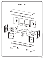
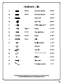
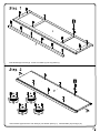
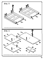
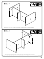
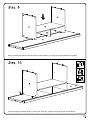
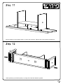
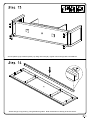
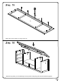
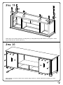
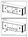
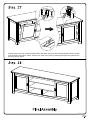
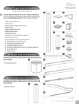
Handle back plate
Inset dowels (A) into slat (2). Screw cam bolts (C) into top panel (1).
Insert dowels (A) and screw cam bolts (C) into bottom panel (11). Insert dowels (A) into legs (13).
Insert dowels (A) and screw cam bolts (C) into panels (3,4).
Insert dowels (B) into panel (9). Insert dowels (A) into panels (5,6,10). Screw cam bolts (C) into panels (5,6,9,10).
Attach panel (10) to panel (9) using cam bolts and dowels as guides. Secure panel (10) to panel (9) using cam
locks (D). Tighten cam locks (D) with a screwdriver.
Attach panels (5,6) to panel (9) using cam bolts and dowels as guides.
Secure panel (5) to panel (9) using cam locks (D). Tighten cam locks (D) with a screwdriver.
Secure panel (6) to panel (9) using cam locks (D). Tighten cam locks (D) with a screwdriver.
Attach the assembly from the previous step to bottom panel (11) using cam bolts and dowels as guides.
Secure panel (5) to bottom panel (11) using cam locks (D). Tighten cam locks (D) with a screwdriver.
Secure panels (6,10) to bottom panel (11) using cam locks (D). Tighten cam locks (D) with a screwdriver.
Attach panels (3,4) to bottom panel (11) using cam bolts and dowels as guides.
Secure panels (3,4) to bottom panel (11) using cam locks (D). Tighten cam locks (D) with a screwdriver.
Attach slat (2) to top panel (1) using dowels as guides. Note the direction of slat (2) as shown above.
Attach slat (2) to top panel (1) using screws (H).
Attach the top panel (1) to the assembly from the previous step using cam bolts and dowels as guides.
Secure top panel (1) to panels (3,6) using cam locks (D). Tighten cam locks (D) with a screwdriver.
4
Secure top panel (1) to panels (4,5) using cam locks (D). Tighten cam locks (D) with a screwdriver.
Attach legs (13) to bottom panels (3,4) using bolts (J), spring washers (K) and washers (L) as guides. Screw
support legs (12) into bottom panel (11).
Attach panels (14,15) to the back of the console using screws (F). Note the direction of panels (14, 15) as
shown above.
Attach panel (16) to the back of the console using screws (F). Note the direction of panel (16) as shown above.
Attach panel (17) to the back of the console using screws (F).
Cover all visible cam locks with stickers (P) as desired.
Insert shelf support pins (E) into panels (3,4,5,6).
Carefully place shelves (7,8) into the console. Note the direction of the shelves as shown in the diagram.
Shelves will rest on the shelf support pins.
Place the handle back plate (N) into handle (M). Attach the handles (M,N) to doors (18,19) using handle
screws (G)
Insert the doors into the console by pulling down the upper door pins and carefully placing the door wheels
over the slide in the bottom panel. Secure the doors into place by pressing the upper door pins into the
groove in the top panel.