1
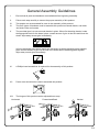
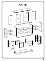
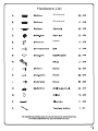
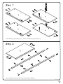
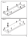
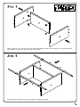
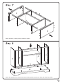
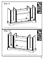
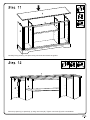
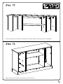
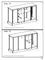
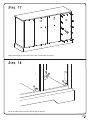
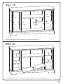
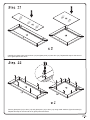
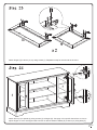
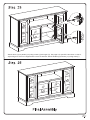
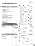
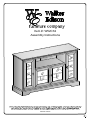
Item #: W52C32
Assembly Instructions
Revised 07/2012
General Assembly Guidelines
I.
Ensure that all parts and hardware are available before beginning assembly.
II.
Follow each step carefully to ensure the proper assembly of this product.
III.
Two people are recommended for ease in the assembly of this product.
IV.
The main types of hardware used to assemble this product are wood dowels, cam bolts
and locks, bolts and screws.
V.
The provided glue is to secure wood dowels in place. When first inserting dowels, locate
the appropriate hole for the dowel, place a small amount of glue in the hole and insert the
dowel. Wipe away excess glue immediately.
In future assembly steps when dowels are necessary to attach assembly parts together,
place a small amount of glue on the end of the dowel before attaching parts together.
Wipe away excess glue immediately.
VI.
A Phillips head screwdriver is required for the assembly of this product.
VII.
Power tools should not be used to assemble this product.
VIII.
The hinges of this product can be adjusted three ways:
Horizontal
Forward and Back
Vertical
P.2
Hardware List
Wood dowel
Wood dowel
Handle
Insert dowels (A) into panels (2,3,4). Screw cam bolts (C) into panels (3,4).
Insert dowels (B) into panel (6). Insert dowels (A) into slats (9).
Screw cam bolts (C) into top panel (1).
Screw cam bolts (C) into bottom panel (5).
Attach panels (3,4) to panel (6) using cam bolts and dowels as guides. Secure panels (3,4) to panel (6) using
cam locks (D). Tighten cam locks (D) with a screwdriver.
Attach slats (9) to panels (3,4) using cam bolts and dowels as guides.
Attach panels (2) to slats (9) using dowels as guides.
Attach the assembly from the previous step to bottom panel (5) using cam bolts and dowels as guides.
Secure panels (2,4) to bottom panel (5) using cam locks (D). Tighten cam locks (D) with a screwdriver.
Secure panels (2,3) to bottom panel (5) using cam locks (D). Tighten cam locks (D) with a screwdriver.
Carefully fit top panel (1) into place using cam bolts and dowels as guides.
Secure top panel (1) to panels (2,4) using cam locks (D). Tighten cam locks (D) with a screwdriver.
Secure top panel (1) to panels (2,3) using cam locks (D). Tighten cam locks (D) with a screwdriver.
Attach panel (10) to the back of the console using screws (L).
Attach panel (11) to the back of the console using screws (L).
Attach panel (12) to the back of the console using screws (L).
Attach second panel (10) to the back of the console using screws (L).
Cover all visible cam locks with stickers (N) as desired.
Insert shelf support pins (M) into panels (2,3,4) at desired shelf heights.
Carefully place shelves (7,8) in console. Shelves (7,8) will rest on the shelf support pins.
Carefully lay glass pane (16) into door (13) and glass pane (15) into door (14). Repeat this step for the second
set of glass panes and doors.
Secure glass pane (16) to door (13) and glass pane (15) to door (14) using metal washers (G) and screws (K).
Repeat this step for the second set of glass panes and doors.
Attach hinges (H) to doors (13,14) using screws (J). Repeat this step for the second set of doors.
Attach doors (13) to panels (2) using screws (J) at hinges (H). See page 2 for specific instructions on how to
adjust hinges so doors are aligned with console as desired. Attach handles (E) to doors (13) using bolts (F).
16
Attach doors (14) to panels (3,4) using screws (J) at hinges (H). See page 2 for specific instructions on how to
adjust hinges so doors are aligned with console as desired. Attach handles (E) to doors (14) using bolts (F).