1
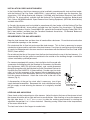
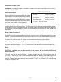
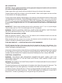
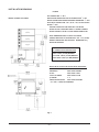
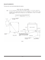
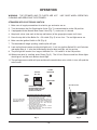
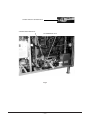
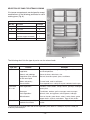
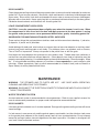
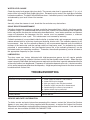
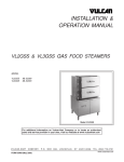
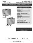
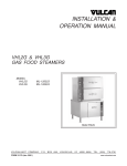
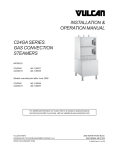
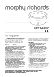
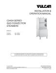
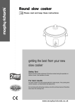
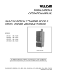
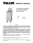
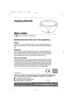
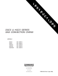
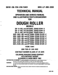
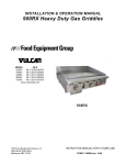
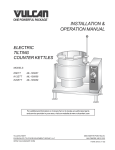
INSTALLATION &
OPERATION MANUAL
VL2GSS & VL3GSS GAS FOOD STEAMERS
MODEL
VL2GSS
VL3GSS
ML-52389
ML-52393
Model VL2GSS
For additional information on Vulcan-Hart or to locate an authorized parts
and service provider in your area, visit our website at www.vulcanhart.com
VULCAN-HART
DIVISION OF ITW FOOD EQUIPMENT GROUP, LLC
WWW.VULCANHART.COM
P.O. BOX 696, LOUISVILLE, KY 40201-0696
TEL. (502) 778-2791
FORM 35409 Rev. A (Aug. 2004)
IMPORTANT FOR YOUR SAFETY
THIS MANUAL HAS BEEN PREPARED FOR PERSONNEL QUALIFIED TO INSTALL GAS
EQUIPMENT, WHO SHOULD PERFORM THE INITIAL FIELD START-UP AND
ADJUSTMENTS OF THE EQUIPMENT COVERED BY THIS MANUAL.
POST IN A PROMINENT LOCATION THE INSTRUCTIONS TO BE FOLLOWED IN THE
EVENT THE SMELL OF GAS IS DETECTED. THIS INFORMATION CAN BE OBTAINED
FROM THE LOCAL GAS SUPPLIER.
IMPORTANT
IN THE EVENT A GAS ODOR IS DETECTED, SHUT DOWN
UNITS AT MAIN SHUTOFF VALVE AND CONTACT THE LOCAL
GAS COMPANY OR GAS SUPPLIER FOR SERVICE.
FOR YOUR SAFETY
DO NOT STORE OR USE GASOLINE OR OTHER FLAMMABLE
VAPORS OR LIQUIDS IN THE VICINITY OF THIS OR ANY
OTHER APPLIANCE.
WARNING: IMPROPER INSTALLATION, ADJUSTMENT,
ALTERATION, SERVICE OR MAINTENANCE CAN CAUSE
PROPERTY DAMAGE, INJURY OR DEATH. READ THE
INSTALLATION, OPERATING AND MAINTENANCE
INSTRUCTIONS THOROUGHLY BEFORE INSTALLING OR
SERVICING THIS EQUIPMENT.
IN THE EVENT OF A POWER FAILURE, DO NOT ATTEMPT TO
OPERATE THIS DEVICE.
© VULCAN-HART, 2003
–2–
TABLE OF CONTENTS
GENERAL
......................................................... 4
INSTALLATION . . . . . . . . . . . . . . . . . . . . . . . . . . . . . . . . . . . . . . . . . . . . . . . . . . . . . . .
Unpacking . . . . . . . . . . . . . . . . . . . . . . . . . . . . . . . . . . . . . . . . . . . . . . . . . . . . . .
Remove the Burner Shipping Restraint . . . . . . . . . . . . . . . . . . . . . . . . . . . . . .
Location . . . . . . . . . . . . . . . . . . . . . . . . . . . . . . . . . . . . . . . . . . . . . . . . . . . . . . .
Installation Codes and Standards . . . . . . . . . . . . . . . . . . . . . . . . . . . . . . . . . . .
Requirements for Gas Appliances. . . . . . . . . . . . . . . . . . . . . . . . . . . . . . . . . . .
Leveling and Anchoring . . . . . . . . . . . . . . . . . . . . . . . . . . . . . . . . . . . . . . . . . . .
Plumbing Connections . . . . . . . . . . . . . . . . . . . . . . . . . . . . . . . . . . . . . . . . . . . .
Water Requirements . . . . . . . . . . . . . . . . . . . . . . . . . . . . . . . . . . . . . . . . . .
Water Supply Connections . . . . . . . . . . . . . . . . . . . . . . . . . . . . . . . . . . . . .
Drain . . . . . . . . . . . . . . . . . . . . . . . . . . . . . . . . . . . . . . . . . . . . . . . . . . . . . .
Gas Connection . . . . . . . . . . . . . . . . . . . . . . . . . . . . . . . . . . . . . . . . . . . . . . . . .
Testing the Gas Supply System . . . . . . . . . . . . . . . . . . . . . . . . . . . . . . . . . . . .
Flue-Gas Exhaust — A Ventilating Hood is Recommended . . . . . . . . . . . . . .
Electrical Connection . . . . . . . . . . . . . . . . . . . . . . . . . . . . . . . . . . . . . . . . . . . . .
Installation Drawing . . . . . . . . . . . . . . . . . . . . . . . . . . . . . . . . . . . . . . . . . . . . . .
Drain Requirements . . . . . . . . . . . . . . . . . . . . . . . . . . . . . . . . . . . . . . . . . . . . . .
4
4
4
4
5
5
5
6
6
6
6
7
7
7
7
8
9
OPERATION . . . . . . . . . . . . . . . . . . . . . . . . . . . . . . . . . . . . . . . . . . . . . . . . . . . . . . . .
Steamers with Electronic Ignition . . . . . . . . . . . . . . . . . . . . . . . . . . . . . . . . . .
Steam Cooking — Compartment Operation . . . . . . . . . . . . . . . . . . . . . . . . . .
Shut Down at End of Day . . . . . . . . . . . . . . . . . . . . . . . . . . . . . . . . . . . . . . . . .
To Shut Off for an Extended Shutdown . . . . . . . . . . . . . . . . . . . . . . . . . . . . .
Selection of Pans for Steam Cooking . . . . . . . . . . . . . . . . . . . . . . . . . . . . . . .
Cleaning . . . . . . . . . . . . . . . . . . . . . . . . . . . . . . . . . . . . . . . . . . . . . . . . . . . . . .
Cooking Compartment Drains . . . . . . . . . . . . . . . . . . . . . . . . . . . . . . . . . . . . .
Boiler Blowdown . . . . . . . . . . . . . . . . . . . . . . . . . . . . . . . . . . . . . . . . . . . . . . . .
Compartments . . . . . . . . . . . . . . . . . . . . . . . . . . . . . . . . . . . . . . . . . . . . . . . . .
Door Gaskets . . . . . . . . . . . . . . . . . . . . . . . . . . . . . . . . . . . . . . . . . . . . . . . . . .
Leave Compartment Doors Open . . . . . . . . . . . . . . . . . . . . . . . . . . . . . . . . . .
Guidelines for Maintaining Stainless Steel Surfaces . . . . . . . . . . . . . . . . . . .
10
10
12
12
12
13
14
14
14
14
15
15
15
MAINTENANCE . . . . . . . . . . . . . . . . . . . . . . . . . . . . . . . . . . . . . . . . . . . . . . . . . . . . . .
Water Treatment System . . . . . . . . . . . . . . . . . . . . . . . . . . . . . . . . . . . . . . . . .
Door Gaskets . . . . . . . . . . . . . . . . . . . . . . . . . . . . . . . . . . . . . . . . . . . . . . . . . .
Water Level Gauge . . . . . . . . . . . . . . . . . . . . . . . . . . . . . . . . . . . . . . . . . . . . .
Flue . . . . . . . . . . . . . . . . . . . . . . . . . . . . . . . . . . . . . . . . . . . . . . . . . . . . . . . .
Scale Related Maintenance . . . . . . . . . . . . . . . . . . . . . . . . . . . . . . . . . . . . . . .
Lubrication . . . . . . . . . . . . . . . . . . . . . . . . . . . . . . . . . . . . . . . . . . . . . . . . . . . .
15
15
15
16
16
16
16
TROUBLESHOOTING . . . . . . . . . . . . . . . . . . . . . . . . . . . . . . . . . . . . . . . . . . . . . . . . . 16
Service and Parts Information . . . . . . . . . . . . . . . . . . . . . . . . . . . . . . . . . . . . . 16
–3–
Installation, Operation and Care of
VL2 & VL3 GAS FOOD STEAMERS
SAVE THESE INSTRUCTIONS FOR FUTURE USE
GENERAL
Vulcan-Hart suggests that you thoroughly read this entire manual and carefully follow all of the
instructions provided. Your Vulcan Model VL Food Steamer is produced with quality workmanship and
materials. Its boiler is fully automatic with the heat input controlled by preset pressure switches. A
solenoid valve feeds makeup water as needed. The steamer is equipped with adjustable feet.
Proper installation, usage and maintenance of your food steamer will result in many years of
satisfactory performance.
INSTALLATION
Before installing, verify that the electrical service and gas supply (natural or propane) agrees with the
specifications on the rating plate located on the boiler access door. If the supply and equipment
requirements do not agree, do not proceed with the installation. Contact your dealer or Vulcan-Hart
immediately.
UNPACKING
This food steamer was inspected before leaving the factory. The
transportation company assumes full responsibility for safe delivery
upon acceptance of the shipment.
IMPORTANT: Immediately after unpacking, check for possible
shipping damage. If the food steamer is found to be damaged, save
the packaging material and contact the carrier within 15 days of
delivery.
REMOVE THE BURNER SHIPPING RESTRAINT
The steamer is shipped as a complete unit and no assembly is
required. However, the burner shipping restraint must be removed
(Fig. 1). To do this, remove two hex nuts and two washers from the
weldstuds on the boiler shell.
Fig. 1
LOCATION
Position the food steamer in its final location. Check that there are sufficient clearances to service the
controls, for door swings, etc., so there will be no problem in making the required supply and drain
connections. Recommended clearances for proper operation is 36" (91.4 cm) at the front. The required
minimum clearance from combustible or noncombustible construction is 6" (15 cm) at the sides and
back. The recommended clearances for servicing the steamer are 18" (46 cm) on the sides and back,
and 36" (91.4 cm) in the front. Clearances less than 18" may require removal of adjacent equipment
during servicing at customer's expence.
Allow enough space between any other piece of equipment or a wall for access. All service on the
compartment controls begins by removing the panel on the left side of the food steamer.
Refer to the Installation Drawing on page 8 for installation location requirements.
–4–
INSTALLATION CODES AND STANDARDS
In the United States, the Vulcan steamer must be installed in accordance with state and local codes,
with the National Fuel Gas Code, (ANSI-Z223.1, latest edition) available from the American Gas
Association, 1515 Wilson Boulevard, Arlington, VA 22209, with the National Electrical Code (ANSI/
NFPA No. 70, latest edition) available from the National Fire Protection Association, Batterymarch
Park, Quincy, MA 02269 and with Vapor Removal from Cooking Equipment, (NFPA-96, latest edition)
available from NFPA.
In Canada, the steamer must be installed in accordance with local codes, with the National Fuel Gas
Code (CAN/CGA-B149.1 latest edition) available from the Canadian Gas Association, 178 Rexdale
Boulevard, Etobicoke, Ontario, Canada M9W 1R3, and with the Canadian Electrical Code (CSA C22.2
No.3, latest edition) available from the Canadian Standards Association, 178 Rexdale Boulevard,
Etobicoke, Ontario, Canada M9W 1R3.
REQUIREMENTS FOR GAS APPLIANCES
Keep the food steamer free and clear from all combustible substances. Do not obstruct combustion
and ventilation openings on the steamer.
Do not obstruct the air flow into and around the food steamer. This air flow is necessary for proper
combustion of gases and for ventilation of the food steamer. Provisions for ventilation and for incoming
air supply for the equipment in the room must be in accordance with the National Fuel Gas Code, ANSI
Z223.1 (latest edition).
Do not obstruct the flow of flue gases from the flue duct located on the rear of the food steamer. It is
recommended that the flue gases be ventilated to the outside of the building through a ventilation
system installed by qualified personnel.
For steamers equipped with casters, the installation shall be made with
a connector that complies with the Standard for Connectors for Movable
Gas Appliances, ANSI Z21.69 (latest edition), and a quick-disconnect
device that complies with the Standard for Quick-Disconnect Devices for
Use With Gas Fuel, ANSI Z21.41 (latest edition). Provide a gas line strain
relief to limit the movement of the steamer without depending on the
connector and any quick-disconnect device or its associated piping to
limit the steamer movement. Attach the strain relief to the rear of the
steamer (Fig. 2).
If disconnection of the gas line strain relief is necessary, turn off gas
supply before disconnection. Reconnect this strain relief before turning
the gas supply on and returning the steamer to its originally installed
position.
5/16 IN. DIA. HOLE
PROVIDED FOR
PL-52057
STRAIN RELIEF
Fig. 2
LEVELING AND ANCHORING
Place a level on the horizontal parts of the steamer. Adjust the feet at the base of the steamer to level
the steamer in both the left-to-right and front-to-rear directions. After leveling, raise up the steamer on
the right side about 1/16" to 1/8" (0.16 to 0.32cm) to drain the cooking compartments by rotating the
adjustable flanged feet 1 to 11/2 turns clockwise. Check by pouring a little water in the compartment;
all the water should drain.
The feet have holes in the flanges for anchor bolts.
–5–
PLUMBING CONNECTIONS
WARNING: PLUMBING CONNECTIONS MUST COMPLY WITH APPLICABLE SANITARY, SAFETY
AND PLUMBING CODES.
WATER REQUIREMENTS
Water Requirements
Proper water quality can improve the taste of the
food prepared in the steamer, reduce liming in the
steam generator and extend equipment life. Local
water contitions vary from one location to another.
Ask your municipal water supplier for details about
your local water supply prior to installation.
Supply Pressure
Hardness*
Silica
Total Chlorine
pH range
Undissolved Solids
*
20 — 60 psig
less than 3 grains
less than 13 ppm
less than 4.0 ppm
7—8
less than 5 microns
17.1 ppm = 1 grain of hardness
Presence of sediment, silica, excess chlorides or other dissolved solids may lead to a recommendation
for alternate form(s) of water treatment. Test the water with the test strip included with the steamer.
Other factors affecting steam generation are iron content, amount of chloridation and dissolved gases.
A local water treatment specialist should be consulted before installation of steam generating
equipment.
Water Supply Connections
A water filter system is recommended for the water supply line going to the treated water inlet of your
steamer. Follow the recommendations for use and installation instructions shipped with the water filter.
If a water filter is not installed, the steamer or steam generator warranty may be limited.
Filtered Water Connection — 1/4" NPT. Used for boiler feed water.
Unfiltered Water Connection — 1/4" NPT. Used as cold water condenser on boiler blow-down line.
Drain
CAUTION: In order to avoid any back pressure in the steamers, do not connect solidly to any
drain connection.
The drain must be the open air gap type. Provide a suitable floor sink with a minimum depth of
12" (30 cm). The floor sink is NOT to be located directly under the steamer. Local codes require that
the maximum temperature of drain water must be no greater than 140°F (60°C). Refer to Fig. 4 on
page 9. The drain pipe should be either iron or copper. DO NOT use PVC pipe; PVC pipe may lose
its rigidity or glue may fail.
–6–
GAS CONNECTION
CAUTION: All gas supply connections and any pipe joint compound used must be resistant to
the action of liquefied petroleum gases.
Codes require that a gas shutoff valve be installed in the gas line ahead of the steamer.
Connect the gas supply line to the gas valve on the steamer. Make sure the pipes are clean and free
of obstructions, dirt and piping compound.
The gas line must be capable of delivering gas to the steamer without excessive pressure drop at the
rate specified on the nameplate. Recommended gas line pressure is 7" W.C. (17.8 cm W.C.) for natural
gas and 11" W.C. (27.9 cm W.C.) for propane gas. Refer to Fig. 3 on page 8. With adequate gas pressure,
a 3/4" (1.9 cm) inside diameter black iron pipe to the steamer should be satisfactory. If adequate pressure
is not available, a larger line such as 1" (2.5 cm) inside diameter may be used to assure adequate gas
delivery.
IMPORTANT: Check burner manifold pressure with a manometer at the 1/8" (0.32 cm) tap on the gas
valve to make sure it is 4" W.C. for natural gas or 9" W.C. for propane.
WARNING: PRIOR TO LIGHTING, CHECK ALL JOINTS IN THE GAS SUPPLY LINE FOR LEAKS.
USE SOAP AND WATER SOLUTION. DO NOT USE AN OPEN FLAME.
TESTING THE GAS SUPPLY SYSTEM
When test pressures exceed 1/2 psig (3.45 kPa), the steamer and its individual shutoff valve must be
disconnected from the gas supply piping system.
When test pressures are 1/2 psig (3.45 kPa) or less, the steamer must be isolated from the gas supply
system by closing its individual manual shutoff valve.
FLUE-GAS EXHAUST — A VENTILATING HOOD IS RECOMMENDED
DO NOT obstruct the flow of flue gases from the flue located on the rear of the steamer. It is
recommended that the flue gases be ventilated to the outside of the building through a ventilation
system installed by qualified personnel.
Information on the construction and installation of ventilating hoods may be obtained from the standard
for the Removal of Vapors from Commercial Cooking Equipment, NFPA No. 96 (latest edition),
available from the National Fire Protection Association, Batterymarch Park, Quincy, MA 02269.
ELECTRICAL CONNECTION
WARNING: ELECTRICAL AND GROUNDING CONNECTIONS MUST COMPLY WITH THE
APPLICABLE PORTIONS OF THE NATIONAL ELECTRICAL CODE AND/OR OTHER LOCAL
ELECTRICAL CODES.
WARNING: DISCONNECT THE ELECTRICAL POWER TO THE MACHINE AND FOLLOW LOCKOUT
/ TAGOUT PROCEDURES.
The electrical diagram for the compartments is located on the inside of the upper left side panel. The
electrical diagram for the steam generator is located on the inside of the left front door.
The electrical supply (120 volt, 60 Hertz, 1 Phase) must be connected to the pigtail leads in the junction
box located next to the boiler control box. Use #18 AWG copper wire suitable for at least 105°C
temperature. Connect a grounding wire to the ground lug in the junction box.
–7–
INSTALLATION DRAWING
LEGEND
GAS CONNECTION: 3/4" NPT
Models VL2GSS & VL3GSS
BOILER FEED CONNECTION FOR FILTERED WATER: 1/4" NPT
WATER CONNECTION FOR BOILER DRAIN CONDENSER: 1/ 4" NPT
ELECTRICAL CONNECTION: 120 V, 60 HZ, 1 PH, 300 WATTS MAX
DRAIN: 3 1/2" DIA.
PROVIDE FLOOR SINK FOR OPEN GAP TYPE DRAIN.
DO NOT PLACE FLOOR SINK DIRECTLY UNDER STEAMER.
DO NOT CONNECT SOLIDLY TO ANY DRAIN CONNECTION.
NOTE: DIMENSIONS WHICH LOCATE THE ABOVE
CONNECTIONS HAVE A TOLERANCE OF + OR - 3 IN. (75 MM).
NORMAL DIMENSIONS ARE IN INCHES. DIMENSIONS IN ( )
ARE IN MILLIMETERS.
EQUIPMENT CLEARANCES
TO COMBUSTIBLE CONSTRUCTION
REAR: 6 INCH (152 MM) MINIMUM
LEFT SIDE: 6 INCH (152 MM) MINIMUM
RIGHT SIDE: 6 INCH (152 MM) MINIMUM
WATER QUALITY MUST BE WITHIN THESE GUIDELINES:
SUPPLY PRESSURE:
20 - 60 PSIG
HARDNESS*:
LESS THAN 3 GRAINS
SILICA:
LESS THAN 13 PPM
TOTAL CHLORINE:
LESS THAN 4.0 PPM
pH RANGE:
7–8
UNDISSOLVED SOLIDS:
LESS THAN 5 MICRONS
* 17.1 PPM = 1 GRAIN OF HARDNESS
Fig. 3
–8–
DRAIN REQUIREMENTS
The floor sink is not to be located under the steamer.
Fig. 4
–9–
OPERATION
WARNING: THE STEAMER AND ITS PARTS ARE HOT.
CLEANING AND SERVICING THE STEAMER.
USE CARE WHEN OPERATING,
STEAMERS WITH ELECTRONIC IGNITION
1. Make sure all supply connections for electric, gas and water are on.
2. Turn the knob on the Gas Combination Valve (Fig. 7) counterclockwise to the ON position.
3. If equipped with the Manual Blow Down Valve (Fig. 7), make sure it is closed.
4. Keep both valves (one each at the top and bottom) of the gauge glass open at all times.
5. Press the top half of the Boiler On – Off switch (Fig. 5) to turn it on. The red light comes on.
6. Make sure the Ignition Switch is ON (Fig. 6).
7. The electrode will begin sparking, and the pilot will light.
8. Look at pilot flame to make sure the pilot light has lit. If not, turn Ignition Switch Off, wait 5 minutes
and repeat Step 6. If after the third attempt the pilot does not light, call for service.
9. The pilot light will remain lit as long as the Boiler On – Off switch is in the ON position.
10. When water level is satisfied, press Reset (Fig. 5). The Hi Limit Pressure and Low Water lights
should go off and the main Burner should light.
11. The cycling pressure switch will open and close the combination valve, which, in turn, will cycle the
main burner.
HI LIMIT
BOILER
RESET
PRESSURE
ON - OFF
LOW WATER
IGNITION SWITCH
DISCONNECT POWER
BEFORE REMOVING THIS
OR ANY PANEL GIVING
ACCESS TO PARTS.
BOILER OPERATING INSTRUCTIONS
FOR SUPPLY CONNECTIONS
USE 18 AWG COPPER WIRE
SUITABLE FOR AT LEAST
221°F (105°C)
1) KEEP BOTH WATER GAUGE VALVES OPEN AT ALL TIMES
2) BE SURE WATER INLET VALVE IS OPEN. CLOSE ONLY
FOR SERVICE OR LONG SHUT DOWN
3) TO START UNIT, PRESS 'BOILER ON-OFF' SWITCH. THE
RED LIGHT WILL COME ON. WHEN THE WATER LEVEL IS
SATISFIED, PRESS RESET SWITCH. THE AMBER LOW
WATER INDICATOR AND THE HI LIMIT PRESSURE
INDICATOR WILL GO OUT.
4) ALLOW 15 MINUTES FOR HEAT UP TIME.
5) TO TURN OFF, PRESS BOILER SWITCH. THE RED
INDICATOR LIGHT WILL GO OFF.
6) BLOW DOWN BOILER DAILY. REFER TO OPERATING
MANUAL FOR INSTRUCTIONS.
Fig. 5
Fig. 6
– 10 –
OPTIONAL MANUAL BLOW DOWN VALVE
AUTOMATIC BLOW DOWN VALVE
GAS COMBINATION VALVE
Fig. 7
– 11 –
STEAM COOKING — COMPARTMENT OPERATION
Refer to the Steam Cooking with Vulcan Kettles and Steamers (booklet packed with your steamer) for
suggested cooking times of various foods. All cooking times are approximate because size, weight,
pan loading and product quality will affect steamer cooking times. Use these suggestions and then
adjust cooking times to your own requirements.
1. Prepare vegetables, fruits, meats, seafood and poultry as you would for steam cooking or cooking
in water, clean, separate, cut, remove stems, and place in a pan.
2. Place loaded pans in the compartment and close the compartment door. Turn the door screw
handle clockwise to seal the door gasket. Additional tightening of the door screw may be needed
to eliminate leaks. The compartment pressure gauge typically reaches a maximum pressure of
(5 to 6 psi).
3. The timer knob must be turned to 5 minutes or beyond. The knob may then be turned back to a
lower setting if a shorter cooking cycle is desired. Set the timer to the sum of the desired cooking
time plus some minutes allowed for preheat. The preheat allowance will generally be 5 to 10
minutes. It will vary with the type, size, temperature and condition (frozen or thawed) of the load,
and must be determined from experience.
4. Press the top half of the red switch located under the timer; the cooking light will come on. This
closes the drain, allows steam to enter the compartment and starts the timer. The balance of the
cooking time sequence is automatic. If steam leaks around the door gasket, tighten the door screw.
Do not overtighten the door screw. Excessive tightening of the door screw may shorten gasket life
and result in steam leakage around the gasket.
5. Steam automatically exhausts one minute before the end of the cooking cycle, and the steam
supply shuts off. Never attempt to open the compartment door during the cooking cycle, when the
cooking light is lit or before the buzzer sounds.
6. At the end of the cooking cycle (and the 1 minute exhaust period), the cooking light shuts off and
the buzzer sounds. Turn the compartment switch off by pressing the bottom half of the red switch;
this also shuts off the buzzer. Loosen the door screw and allow moisture to escape. After a few
seconds, move the latch paddle to the left, then slowly open the door and remove the pans of food.
SHUT DOWN AT END OF DAY
WARNING: THE WATER BEING DRAINED IS HOT AND UNDER PRESSURE. USE CARE WHEN
SERVICING THE STEAM GENERATOR.
To prevent malfunction of controls from scale related clogging, it is essential to flush (blow down)
the steam generator every day. This will remove accumulated minerals from the feed water and
reduce internal scale build-up which could interfere with proper steam generator operation.
Failure to blow down the steam generator every day may void the steamer warranty.
1. Turn the power switch OFF. Steamers equipped with automatic blow down will blow down.
2. If your steamer is equipped with manual blow down, open the blow down valve.
TO SHUT OFF FOR AN EXTENDED SHUTDOWN
For an extended shutdown, turn the Boiler On-Off switch off; turn the Ignition Switch off. Allow to blow
down before water is shut off. Close the water inlet valve(s). Close the gas shutoff valve. Shut off the
electrical supply to the machine. Clean the compartments. Leave the doors open.
– 12 –
SELECTION OF PANS FOR STEAM COOKING
VL steamer compartments are designed to accept
combinations of the following perforated or solid
cooking pans (Fig. 8):
PAN ACCOMODATION, PER COMPARTMENT
Max Qty
Pan Size
Pan Depth
4
12 X 20
6
6
12 X 20
4
8
12 X 20
2 1/ 2
6
18 X 26
16
(center support removed)
1
12 x 20
1
Fig. 8
The following chart lists the type of pan to use for various foods:
FRESH PRODUCT
Type Pan
Product
Solid 12" x 20" Dehydrated fruits and
vegetables
Perforated
12" x 20"
18" x 26"
Examples
Dried peaches, prunes, apples, and appricots. Sliced onions
and sliced potatoes.
Cereals and puddings
Cream of wheat, rolled oats, rice.
Vegetables to be cooked
in their own liquid
Broccoli, brussels sprouts, peas, cauliflower.
Meats and poultry
To save broth, cook in solid pans.
Canned foods
Place opened can in solid pan or pour contents into the pan.
Root vegetables*
Potatoes, carrots, beets, turnips, onions, parsnips, rutabagas
oyster plant.
Sausages
Frankfurters, weiners, garlic sausages, meat sausages.
Leaf vegetables*
Spinach, kale, turnip greens, collard greens, cabbage.
Miscellaneous
Corn on the cob, green beans, celery / celery hearts, green
pepper shells, squash, mushrooms. Eggs in their shells.
Precooked and partially
cooked sliced meats
Ham, meat loaf, roast beef, chicken, turkey, hamburger
patties.
* If you wish to save liquids from root or leaf vegetables, place them in a solid pan, or place a solid pan
undet the perforated pan.
– 13 –
FROZEN PRODUCT
Perforated
Frozen Vegetables.
Loosen
and
spread
vegetable.
Broccoli, asparagus spears, green beans, carrots,
brussel sprouts, turnips, potatoes, cut corn, lima beans,
peas, squash.
Solid
Precooked Dishes.
Remove wrapping and place
in pan.
All precooked dishes, such as beef goulash, chicken
fricasse, etc., which cannot be cooked in the containers
in which they are packed.
Separate frozen food packs into smaller chunks.
If unpacked pre-cooked frozen dishes require more than 15 minutes to cook, cover the pan. When a
cover is used, about one-third more cooking time is required. This is true only of foods in either portion
size or in larger sizes which cannot be cooked in the covered containers in which they are packed.
Cooking time required for frozen foods depends upon the amount of defrosting required. If time
permits, allow the frozen foods to partially thaw overnight in a refrigerator. This will reduce their
cooking times.
CLEANING
WARNING: DISCONNECT THE ELECTRICAL POWER TO THE MACHINE AND FOLLOW LOCKOUT/
TAGOUT PROCEDURES BEFORE CLEANING.
COOKING COMPARTMENT DRAINS
Keep compartment drains running freely. Inspect compartment drains daily for blockage. Remove any
particles or debris from the perforated strainer daily (or more often if needed).
After cooking greasy foods or seafood, close the doors and operate each compartment for 15 to 30
minutes to flush any residual grease and oils down the compartment drain. Make a solution of warm
water and detergent and pour 1/2 gallon (1.9 liters) of it down each compartment drain. Rinse by pouring
1
/2 gallon (1.9 liters) of hot water down each compartment drain.
BOILER BLOWDOWN
To prevent malfunction of controls from scale related clogging, it is essential to blow down the boiler
every day. This will flush out any accumulated minerals from the feed water. It will also aid in
preventing internal scale buildup which would interfere with proper boiler operation. Failure to blow
down the boiler every day may void the steamer warranty. The presence of minerals in suspension
is indicated by a murky or milky condition in the first portion of the water drained.
WARNING: THE WATER BEING DRAINED IS HOT AND UNDER PRESSURE.
CLEANING OR SERVICING THE BOILER.
USE CARE WHEN
After the steamer boiler has been in operation, blow down the boiler for approximately 5 minutes. This
will remove sediment, scale or lime buildup in the boiler.
COMPARTMENTS
Wash the inside of the compartment with a solution of warm water and detergent. Rinse with warm
water.
Once a week, thoroughly clean the exposed surfaces (sides, front, door and top) with a damp cloth and
polish with a clean cloth. To remove discolorations, use a nonabrasive cleaner.
– 14 –
DOOR GASKETS
Clean the gasket sealing surface of the compartment doors to remove harmful food acids for maximum
gasket life. Do not use any solvents. Wash with a cloth moistened in a solution of mild detergent and
warm water. Rinse with a fresh cloth moistened with warm water to remove all traces of detergent.
Wipe dry with a clean cloth. Never apply food oils or petroleum lubricants directly to the door gasket.
Petroleum-based solvents and lubricants will shorten gasket life.
LEAVE COMPARTMENT DOORS OPEN
CAUTION: Leave the compartment doors slightly open when the steamer is not in use. When
the compartment is idle, never latch the door and apply pressure to the door gasket. Leaving
the gasket under pressure can cause permanent deformation, greatly shortening gasket life.
GUIDELINES FOR MAINTAINING STAINLESS STEEL SURFACES
There are four things that can break down stainless steel and allow corrosion to develop: 1) abrasion,
2) deposits, 3) water and 4) chlorides.
Avoid rubbing with steel pads, wire brushes or scrapers that can leave iron deposits on stainless steel.
Instead, use plastic scouring pads or soft cloths. For stubborn stains, use products such as Cameo,
Talc or Zud First Impression. Always rub parallel to the polish lines or with the grain.
Hard water can leave deposits that promote rust on stainless steel. Treated water from softeners or
certain filters can eliminate these mineral deposits. Other deposits from food or lubrication must be
properly removed by cleaning. Use mild detergent and nonchloride cleaners. Rinse thoroughly. Wipe
dry. If using chloride-containing cleaners or sanitizers, rinse repeatedly to avoid stainless steel
corrosion. Where appropriate, apply a polish recommended for stainless steel (such as Benefit or
Super Sheen) for extra protection and lustre.
MAINTENANCE
WARNING: THE STEAMER AND ITS PARTS ARE HOT.
CLEANING AND SERVICING THE STEAMER.
USE CARE WHEN OPERATING,
WARNING: DISCONNECT THE ELECTRICAL POWER TO THE MACHINE AND FOLLOW LOCKOUT
/ TAGOUT PROCEDURES.
WATER TREATMENT SYSTEM
A water treatment system is recommended for steam generators. Refer to your supplier's manual for
normal maintenance procedures for proper scale-free operation recommendations.
DOOR GASKETS
If the door gasket is nicked or cut, it must be replaced. Damage to the gasket sealing surface will cause
steam leakage.
If a leak occurs in one corner only and the gasket appears serviceable, turn the stainless steel screw
on the gasket plate adjacent to the leaking corner one-half turn counterclockwise. Do not attempt
excessive turning of screws since misalignment of the door is possible. If the door is misaligned, call
your local Vulcan-authorized servicer.
– 15 –
WATER LEVEL GAUGE
Check the water level gauge sight glass daily. The correct water level is approximately 1" ( 2.5 cm) of
water visible in the water level gauge sight glass. Extremely murky water in the sight glass indicates
bad water conditions. The boiler should be blown down. If conditions persist, have the boiler inspected
and cleaned by your local Vulcan-Hart servicer.
FLUE
Annually, when the steamer is cool, check the flue and clear any obstructions.
SCALE RELATED MAINTENANCE
Periodic maintenance is necessary to keep your boiler clean and efficient. Initially, after three months
of steamer usage, it is recommended that you have your Vulcan-Hart authorized servicer inspect the
boiler and perform the descaler maintenance described below. Local water conditions and steamer
usage will determine the frequency that this service must be repeated; however, a minimum
recommendation is once a year. This maintenance is not covered by warranty.
Cathodic protector(s) are provided inside the boiler to reduce boiler and component corrosion and
reduce accumulation of scale from forming on the boiler interior walls. The cathodic protector(s) will
be consumed. How fast the cathodic protector(s) will be consumed depends upon the chemical
makeup of the feed water and the average volume of feed water used. An inspection by service
personnel is recommended so that the expected normal life of the cathodic protector(s) can be
estimated under your operating conditions. Thereafter, the cathodic protector(s) can be serviced at
the appropriate frequency for your situation.
LUBRICATION
The door screw was factory lubricated with high-temperature grease, but will require periodic
relubrication by applying a bead of lubricant across the door handle screw threads. When the door
screw is properly lubricated, the hand pressure required to seal the door is greatly reduced and the life
of the screw and nut are lengthened. Frequency of lubrication depends upon use. Lubricate monthly
at first and let experience determine the frequency. A high-temperature grease for the door screw can
be obtained from Vulcan-Hart.
TROUBLESHOOTING
Symptoms
Possible Causes
Steamer will not heat or build pressure.
1.
2.
3.
4.
5.
6.
Water accumulates in compartment.
Drain may be clogged. Clear drain.
Other problems.
Contact Service.
Water supply to steamer is not turned on.
Water filter may be clogged.
Main gas supply valve may be turned off.
Electrical supply may be off or disconnected.
Combination gas valve may be turned off.
Ignition switch may be turned off.
SERVICE AND PARTS INFORMATION
To obtain service and parts information concerning this steamer, contact the Vulcan-Hart Service
Agency in your area (refer to listing supplied with the steamer), or contact the Vulcan-Hart Service
Department at the address or phone number shown on the front cover of this manual. Parts and service
manuals are also available at WWW.VULCANHART.COM
FORM 35409 Rev. A (Aug. 2004)
– 16 –
PRINTED IN U.S.A.