1
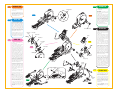
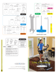
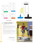
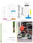
Power Cord
Console Mast Bracket
Console Mast Cover
Accessory Tray
Color-coded Hardware Bags
Owner’s Guide
Assembly Guide
Warranty Card
©2008 Vision Fitness. All Rights Reserved. 3.08
AG18.50PRD
REV6
www.visionfitness.com
toll free 800.335.4348 • phone 920.648.4090 • fax 920.648.3373
COMMERCIAL INCLINE ELLIPTICAL TRAINERS
X6850HRT
500 South CP Avenue • P.O. Box 280 • Lake Mills. WI 53551
8mm L-Shaped Wrench
PARTS BOX
17mm Wrench
5mm L-Shaped Wrench
Assembly
Guide
Screwdriver
6mm L-Shaped Wrench
13mm Wrench
6mm T-Shaped Wrench
TOOLS & PARTS INCLUDED
HARDWARE INCLUDED
X6850HRT
COMMERCIAL INCLINE ELLIPTICAL TRAINERS
To avoid possible damage to this Elliptical Trainer, please follow assembly steps in the correct order. Before proceeding, find your new
Elliptical Trainer’s serial number located on the front axle tube, and enter here:
BLACK BAG
ORANGE BAG
Refer to this number when calling for service, and enter this serial number on your Warranty Card and in your own records.
Be sure to read your Owner’s Guide before using your new Elliptical Trainer.
If any parts, hardware or tools are missing, please call 1.800.335.4348, Extension 12
NOTE: It is recommended that you apply grease to the threads of each bolt and screw as you assemble your Elliptical Trainer to prevent
loosening and noise. Also, during each assembly step, ensure that ALL bolts and screws are in place and partially threaded in before
completely tightening any ONE bolt or screw.
HARDWARE INCLUDED
8x16x1T Washer
Quantity: 2
M8x20L Socket Head Bolt
Quantity: 4
8.2x18x1.5T Arc Washer
Quantity: 4
Spacer
Quantity: 4
M8 Nylon Nut
Quantity: 2
GREEN BAG
PINK BAG
Plastic Connector
Quantity: 4
M8 Lock Washer
Quantity: 4
8x16x2T Washer
Quantity: 4
M5x15L Bolt
Quantity: 8
M10 Lock Washer
Quantity: 4
M10x25L Socket Head Bolt
Quantity: 4
M8x12L Bolt
Quantity: 2
26x36x0.3T Wave Washer
Quantity: 2
M8x25L Socket Head Bolt
Quantity: 8
Zip Tie, Quantity: 1
M8 Lock Washer
Quantity: 8
M8x25L Socket Head Bolt
Quantity: 4
BLUE BAG
End Cap
illustration not to scale
Quantity: 2
26x36x2T Wave Washer
Quantity: 4
M5x12L Bolt
Quantity: 2
10x24.5x1T Washer
Quantity: 4
M8x55L Socket Head Bolt
Quantity: 2
YELLOW BAG
M10 Nylon Nut
Quantity: 2
25.5x38x1T Washer
Quantity: 2
M10x55L Socket Head Bolt
Quantity: 2
M8x20L Panhead Bolt
Quantity: 4
Power Cord
Console Mast Bracket
Console Mast Cover
Accessory Tray
Color-coded Hardware Bags
Owner’s Guide
Assembly Guide
Warranty Card
©2008 Vision Fitness. All Rights Reserved. 3.08
AG18.50PRD
REV6
COMMERCIAL INCLINE ELLIPTICAL TRAINERS
www.visionfitness.com
X6850HRT
toll free 800.335.4348 • phone 920.648.4090 • fax 920.648.3373
500 South CP Avenue • P.O. Box 280 • Lake Mills. WI 53551
8mm L-Shaped Wrench
PARTS BOX
17mm Wrench
5mm L-Shaped Wrench
Assembly
Guide
Screwdriver
6mm L-Shaped Wrench
13mm Wrench
6mm T-Shaped Wrench
TOOLS & PARTS INCLUDED
HARDWARE INCLUDED
X6850HRT
COMMERCIAL INCLINE ELLIPTICAL TRAINERS
To avoid possible damage to this Elliptical Trainer, please follow assembly steps in the correct order. Before proceeding, find your new
Elliptical Trainer’s serial number located on the front axle tube, and enter here:
BLACK BAG
ORANGE BAG
Refer to this number when calling for service, and enter this serial number on your Warranty Card and in your own records.
Be sure to read your Owner’s Guide before using your new Elliptical Trainer.
If any parts, hardware or tools are missing, please call 1.800.335.4348, Extension 12
NOTE: It is recommended that you apply grease to the threads of each bolt and screw as you assemble your Elliptical Trainer to prevent
loosening and noise. Also, during each assembly step, ensure that ALL bolts and screws are in place and partially threaded in before
completely tightening any ONE bolt or screw.
HARDWARE INCLUDED
8x16x1T Washer
Quantity: 2
M8x20L Socket Head Bolt
Quantity: 4
8.2x18x1.5T Arc Washer
Quantity: 4
Spacer
Quantity: 4
M8 Nylon Nut
Quantity: 2
GREEN BAG
PINK BAG
Plastic Connector
Quantity: 4
M8 Lock Washer
Quantity: 4
8x16x2T Washer
Quantity: 4
M5x15L Bolt
Quantity: 8
M10 Lock Washer
Quantity: 4
M10x25L Socket Head Bolt
Quantity: 4
26x36x0.3T Wave Washer
Quantity: 2
M8x12L Bolt
Quantity: 2
M8x25L Socket Head Bolt
Quantity: 8
Zip Tie, Quantity: 1
M8 Lock Washer
Quantity: 8
M8x25L Socket Head Bolt
Quantity: 4
BLUE BAG
26x36x2T Wave Washer
Quantity: 4
M5x12L Bolt
Quantity: 2
10x24.5x1T Washer
Quantity: 4
M10x55L Socket Head Bolt
Quantity: 2
End Cap
illustration not to scale
Quantity: 2
M8x55L Socket Head Bolt
Quantity: 2
YELLOW BAG
M10 Nylon Nut
Quantity: 2
25.5x38x1T Washer
Quantity: 2
M8x20L Panhead Bolt
Quantity: 4
STEP
1
ORANGE BAG
STEP
• Place a piece of packaging under
the front of the unit to aid in assembly
of the front foot.
2
I M P O RTA N T: The washers in the
following step must be assembled in
the correct order.
STEP
2
STEP
• Slide one thin metal wave washer
(26x36x0.3T), one flat washer (25.5x38x1T),
and one plastic wave washer (26x36x2T)
onto the axle of the right link arm. Slide
the axle of the right link arm through the
sleeve on the right pedal arm. Secure
the link arm onto the pedal arm with the
plastic wave washer (26x36x2T), end
cap, and bolt (M8x12L). Tighten with
the 5mm L-shaped wrench.
1
BLUE BAG
• Take the right pedal arm and set the
roller wheel in the aluminum guide track.
Slide the opposite end of the pedal arm
into the U-shaped knuckle bracket.
Slide a socket head bolt (M10x55L)
with a washer (10x24.5x1T) through
the hole in the knuckle bracket and
pedal arm. Fix in place with a
washer (10x24.5x1T) and nylon nut
(M10). Tighten with the 8mm L-shaped
wrench and the 17mm wrench.
• Slide the pedal arm cover over the
knuckle joint and fix in place with a bolt
(M5x12L). Tighten with the screwdriver.
• Repeat these steps on the left side.
• Repeat the step on the left side.
Front Stabilizer Tube
TV Bracket
Cables
STEP
5
3
Data Cable
Console Plate
• Take the right dual-action arm and
center the holes in the rotation housing
on the console mast. Secure with four
socket head bolts (M8x25L) and four
lock washers (M8). Tighten with the
6mm T-shaped wrench.
Console
Heart Rate
Wires
PINK BAG
Console Mast
Boot
• Slide the console mast boot onto
the console mast.
STEP
• Attach the dual-action arm rotation
cover to the dual-action arm center.
Secure in place with two bolts
(M5x15L). Tighten with the screwdriver.
6
• Cut the zip ties holding the cables
and wires onto the console mast.
STEP
• Attach the mounting plate to the
bottom of the console mast with four
socket head bolts (M10x25L) and four
lock washers (M10). Tighten as much as
possible with the 8mm L-shaped wrench.
• Mount the console mast on the
frame by sliding the guide hole on the
mast mounting plate over the guide
screw on the front of the frame bracket.
Place a lock washer (M8) followed by
a flat washer (8x16x2T) on each of
the four remaining socket head bolts
(M8x25L). Insert the bolts to the rear
holes but do not completely tighten.
Next, insert the bolts to the front holes.
Tighten all four bolts as much as possible
with the 6mm L-shaped wrench.
3
Mounting Plate
• Attach the inside dual-action arm
cover onto the bottom of the dualaction arm with a bolt (M5x15L).
Insert the plastic connector to the
inside dual-action arm cover. Slide the
outside dual-action arm cover onto the
other end of the plastic connector.
Secure the outside dual-action arm
cover to the bottom of the dual-action
arm with a bolt (M5x15L). Tighten
both bolts with the screwdriver.
Accessor y Tray
Rotation
Housing
• Repeat these steps on the left side.
End Cap
Plastic Wave
Washer
STEP
• Remove the protective plastic
around the cables and data cable.
Plastic Wave
Washer
• Tuck the coaxial and TV power
cables into the console mast.
• Insert a zip tie through the hole in
the middle of the console plate and
loop it around the heart rate wires and
data cable. Pull to snug, but do not
over tighten.
• Slide a spacer onto each side of the
socket joint located on the end of the
link arm. Slide the bottom of the dualaction arm bracket over the link arm
socket and spacers. From the outside
of the bracket, slide the bolt (M8x55L)
through the hole in the bracket and
socket joint. Secure with a washer
(8x16x1T) and nylon nut (M8).
Tighten with the 6mm T-shaped
wrench and 13mm wrench.
Frame Bracket
• Wrap the wire tie that exits the hole
at the bottom front side of the console
mast around the data cable, coaxial
cable, and TV power cable coming
up from the frame. Pull the wire tie
and all cables up through the top of
the console mast.
NOTE: If you have purchased the TV
bracket assembly, remove the screws
from the TV bracket cover located at
the front of the console mast, and
remove the cover. Feed the coaxial
and TV power cables through the hole
at the front of the console mast.
BLACK BAG
NOTE: With this next step it is helpful
to have a second person to hold the
dual-action arms in place while you
assemble them.
Console Mast
STEP
GREEN BAG
• Remove protective covers from sleeves
of the pedal arms.
Knuckle Bracket
• Secure the front stabilizer tube to the
base frame plate with four socket
head bolts (M8x20L) and four arc
washers (8.2x18x1.5T). Tighten with
the 6mm L-shaped wrench.
STEP
4
Pedal Arm
Flat Washer
4
YELLOW BAG
• Slide the accessory tray onto the
console mast. Secure in place with
four panhead bolts (M8x20L). Tighten
with the 5mm L-shaped wrench.
Thin Metal
Wave Washer
Dual-Action
Arm
STEP
6
Link Arm
STEP
5
• Remove the four bolts (M5x12L)
from the back side of the console.
Connect the data cable and the heart
rate wires to the plugs in the back side
of the console. Place the console on
the mast and secure in place with the
bolts (M5x12L).
• Place the X6850HRT in its intended
location and plug in the power cord
to the electrical outlet.