1
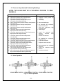
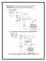
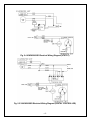
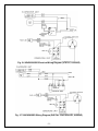
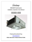
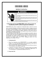
VINO2500SSD, 4500SSD
VINO6500SSD, 8500SSD
Installer’s Instruction
Federal law requires that WINE-MATE split cooling systems be
installed by an EPA certified refrigeration technician.
WINE-MATE split system is shipped as components and is ready for use only
after a certified refrigeration technician has properly installed, chatged and tested
the system. Proper installation is critical. Vinotemp can only warrant the quality of
the components. The installation and proper operation of the system must be
warranted by the installer. Installation of the system must be done in accordance
with all state and local building codes.
The condensing unit and evaporator unit are connected by a liquid line and an
insulated suction line that are supplied by the installer. These lines must be
properly sized for the distance between the two units. After the units and the lines
are installed, the system must be pressure tested. If no leaks are found,
evacuate and charge system with R134A. Refrigerant amount will vary
depending on the length of line set.
1. Condensing Unit
•
•
•
Place the condensing units WM250-850SCU in a properly ventilated
location. If it is not, heat exhausted by the condensing unit will build up
and the cooling system will not operate properly.
Leave minimum 5 feet clearance for the exhaust side and leave minimum
1 foot clearance for the fresh air intake side.
Condensing unit shall be elevated to avoid possible flooding and shaded
from direct sun. It shall not be exposed to temperatures higher than 110
°F or lower than 45 °F (optional low ambient kit for 20 °F).
2. Evaporator Unit
•
•
•
The WM25-85SFCD evaporator units shall be installed for ceiling mount
with air supply on both sides and air return on the bottom.
Supply and return air flow from the evaporator unit shall be unobstructed
for at least 1 foot.
There is a gravity drain line so that it can not be installed above the
evaporator unit. Otherwise a condensation pump must be used.
3. Air Sensor
•
The air sensor can be located in the wine room or the return air area, but
not the supply air area.
4. Refrigeration Piping and Charging
NOTES: ALWAYS USE THE SUPERHEAT AND SUBCOOLING,
PRESSURE READINGS TO CHARGE REFRIGERANT PROPERLY, THE
LISTED CHARGES ARE FOR REFERENCE ONLY.
•
•
•
•
•
•
The installation order starts from condensing unit (including the receiver),
liquid line filter-drier, moisture-liquid indicator (sight glass), liquid line,
evaporator unit (including liquid line solenoid valve and thermostatic
expansion valve or automatic expansion valve), suction line, and returning
to condensing unit.
The subcooling at the condensing unit shall be around 10°F. The charge
may be complete when there are no more bubbles forming in the sight
glass.
If equipped with a TXV, the evaporator superheat is set around 8-10 °F for
a 10 °F TD system at factory.
If equipped with an AXV, the valve is set around 38-40°F at factory and
the superheat at the evaporator unit shall be around 9-18°F under low and
high load at 75°F ambient temperature.
Low side pressure: 33 psig
High side pressure: 130 psig at 75 °F ambient temperature and 150 psig
at 90 °F ambient temperature
The line sizes and refrigerant charges are listed as follows.
MODEL
VINO2500SSD
VINO4500SSD
VINO6500SSD
VINO8500SSD
REFRIGERATION
LINES
< 50 FT
< 50 FT
< 50 FT
< 50 FT
LIQUID
LINE
1/4"
OD
1/4"
OD
1/4"
OD
3/8"
OD
-1-
SUCTION
LINE
DRAIN
LINE
3/8” OD
1/2” OD
1/2” OD
1/2” OD
5/8” OD
1/2” OD
5/8” OD
1/2” OD
CHARGE
R134a/
20 OZ
R134a/
26 OZ
R134a/
32 OZ
R134a/
38 OZ
5. Pressure, Superheat and Subcooling Readings
NOTES: THE VALVES MUST BE IN THE MIDDLE POSITIONS TO READ
PROPERLY.
Complaint
a. High suction pressure and low head pressure
b. High suction pressure and low head pressure
Low superheat and low subcooling
c. High suction pressure and high head pressure
Low superheat and high subcooling
d. High to normal suction pressure and high head pressure
Low subcooling
e. High suction pressure and high head pressure
Low subcooling
f. High suction pressure and high head pressure
High superheat
g. Low suction pressure and low head pressure
High superheat and low subcooling
h. Low suction pressure and low to normal head pressure
High superheat and high subcooling
i.
j.
k.
l.
m.
n.
o.
Low suction pressure and low head pressure
Low subcooling
Low suction pressure and low head pressure
Low superheat and low subcooling
Low suction pressure and low to normal head pressure
High superheat and normal to high subcooling
Low suction pressure and normal head pressure
High superheat and normal subcooling
Low suction pressure and high head pressure
High superheat and high subcooling
Low suction pressure and high head pressure
High superheat and high subcooling
low to normal suction pressure and high head pressure
High to normal superheat and high subcooling
Possible Causes
a. Compressor may be bad
b. Expansion valve opened, too
much oil
c. Overcharge
d. Non-condensable gas
e. Air restricted, dirty condenser,
bad condenser fans
f. High room temperature, high
evaporator load
g. Undercharge
h. Liquid line restricted
receiver,
solenoid
restricted
i. Suction line restricted
j.
after
valve
k.
Air restricted at evaporator,
evaporator iced
Evaporator restricted
l.
Expansion valve restricted
m. Both evaporator and condenser
restricted
n. Liquid line restricted before
receiver
o. Condenser restricted
6. Valve Operation
SPINDLE BACK POSITION
SPINDLE FRONT POSITION
Fig. 2.1 Valve Operation
-2-
SPINDLE MIDDLE POSITION
Back Position: Process and manometer port closed for normal operation
Front Position: Main connection to liquid or suction line closed
Middle Position: All ports open for vacuum, charge and measurement
7. Electrical Wiring
Fig. 2.2 VINO2500 & 4500SSD Electrical Wiring Diagram (VTSTAT)
Fig. 2.3 VINO2500 & 4500SSD Wiring Diagram (DIGITAL CONTROLLER)
-3-
Fig. 2.4 VINO6500SSD Electrical Wiring Diagram (VTSTAT)
Fig. 2.5 VINO6500SSD Electrical Wiring Diagram (DIGITAL CONTROLLER)
-4-
Fig. 2.6 VINO8500SSD Electrical Wiring Diagram (VTSTAT, UJ6220Z)
Fig. 2.7 VINO8500SSD Wiring Diagram (DIGITAL CONTROLLER, UJ6220Z)
-5-
8. Use of the adjustable low pressure control (if applicable)
Cut out = 5 psig; Cut in = 25 psig; Differential = 20 psig
It may need to adjust the setting in the field to get the right cycle time.
8.1 P70AB-12
Fig. 2.8 P70AB-12 Adjustable Low Pressure Control
8.2 PS2-A7A
Fig. 2.9 PS2-A7A Adjustable Dual Pressure Control
-6-
Fig. 3.0 PS2-A7A Wiring Diagram
9. Condensing Unit Troubleshooting
Unit not running
a. Incorrect power supply
b. Incorrect or loose wirings
c. Failed components
d. Liquid refrigerant in the compressor
e. Low pressure switch shutting down the unit
a. Check for proper voltage
b. Check all wirings and connections
c. Check start relay, start capacitor, overload
protector, compressor.
d. Call service for OEM information
e. Check for system restriction or low
refrigerant
-7-