1
Vincent
Bedienungsanleitung
deutsch
Instructions for use
english
Manuel d‘utilisation
français
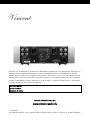
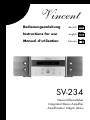
SV-234
Stereo-Vollverstärker
Integrated Stereo Amplifier
Amplificateur intégré stéréo
Sehr geehr ter Kunde,
wir danken Ihnen für das Vertrauen, welches Sie uns durch die Entscheidung für dieses hochwertige AudioProdukt, das Ihrem hohen Anspruch an Klang- und Verarbeitungsqualität gerecht wird, entgegenbringen.
Auch wenn Sie verständlicherweise sofort beginnen wollen, das Gerät zu verwenden, lesen Sie bitte vor
dem Aufstellen und Anschließen dieses Handbuch sorgfältig durch. Es wird Ihnen bei der Bedienung und
der optimalen Nutzung des Gerätes in Ihrem System helfen, selbst wenn dieses durch Ihren Fachhändler
installiert wurde.
Bitte beachten Sie vor allem die Sicherheitshinweise, auch wenn einige davon offensichtlich erscheinen mögen.
Um Ihnen verwendete Fachbegriffe zu erläutern, ist ein kleines Lexikon im Anhang enthalten. Bei eventuellen Fragen steht Ihnen Ihr Fachhändler gern zur Verfügung, er ist auch Ihr Ansprechpartner im Fall der
Garantie-Inanspruchnahme oder für Reparaturen nach dem Gewährleistungszeitraum. Er ist in jedem Fall
interessiert daran, dass Sie ihm Ihre Erfahrungen mit Vincent-Produkten mitteilen.
Viel Freude mit unserem / Ihrem Produkt wünscht Ihnen
Ihr Vincent-Team
Dear Customer,
we thank you for the confidence you prove in purchasing our product. It will match your high demands
towards sound and manufacturing quality. Though it is understandable that you want to plug and play
this product instantaneously, we encourage you to read this manual carefully before installation.
It will help you in handling and operating this machine in your system and obtaining the best possible
performance, even if it was installed by your dealer.
Please follow the security precautions, though some of those things may seem obvious.
In the appendix to this manual you will find a glossary explaining some established technical terms.
If there are open questions your audio specialist dealer will help you. He also represents your contact
person in case of needed warranty service or repairs after the warranty period and is interested to hear
from your experiences with Vincent products.
We wish you plenty of joy with your / our product,
your Vincent-Team
Cher client,
nous vous remercions de la confiance que vous nous témoignez en achetant ce produit de haute qualité.
Il répondra à vos attentes élevées en termes de qualité sonore et de fabrication.
Même si l'on peut comprendre que vous ayez envie d'utiliser immédiatement cet appareil, nous vous prions
de lire soigneusement ce manuel avant son installation et son branchement. Il vous aidera à manier et utiliser l'appareil de manière optimale dans votre système, même si celui-ci a été installé par votre revendeur.
Veuillez respecter les consignes de sécurité, même si certaines peuvent vous paraître évidentes.
Vous trouverez à la fin de ce manuel un petit glossaire qui vous explique les termes techniques utilisés.
Votre revendeur est à votre disposition pour répondre à vos questions. Il est aussi votre interlocuteur en
cas de recours à la garantie ou pour les réparations après la période de garantie. Dans tous les cas, vos
expériences avec les produits Vincent l'intéressent, n'hésitez pas à lui en faire part.
Nous vous souhaitons beaucoup de plaisir avec notre / votre produit.
Votre équipe Vincent
2
Vincent
I N H A LT S V E R Z E I C H N I S / C O N T E N T S / S O M M A I R E
Sicher heitshinweise
Weiter e Hinweise
Lieferumfang
Beschr eibung des Gerätes
Fer nbedienung
Installation
Bedienung des Gerätes
Weiter e Tipps
Fehlersuche
Technische Daten
Lexikon/Wissenswer tes
4
5
6
6
9
11
18
20
21
22
23
deutsch
Security pr ecautions
User Infor mation
Included in deliver y
Description of the device
Remote control
Installation
Operating the appliance
Tips
Troubleshooting
Technical Specifications
Glossar y
24
25
26
26
29
31
38
40
41
42
43
english
Consignes de sécurité
Infor mations complémentaires
Contenu de la livraison
Description de l'appar eil
Télécommande
Installation
Utilisation de l'appar eil
Conseils
Dépannage
Caractéristiques techniques
Lexique
44
45
46
46
49
51
58
60
61
62
63
français
Vincent
3
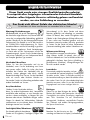
SICHERHEITSHINWEISE
Dieses Gerät wurde unter strengen Qualitätskontrollen gefertigt.
Es entspricht allen festgelegten internationalen Sicherheitsstandards.
Trotzdem sollten folgende Hinweise vollständig gelesen und beachtet
werden, um eine Gefährdung zu vermeiden:
Das Gerät nicht öffnen! Gefahr des elektrischen Schocks!
Es befinden sich keine vom Benutzer zu wartenden Teile im Gerät.
Wartung/Veränderungen
Alle Betriebsmittel, die an die Netzspannung
des Haushalts angeschlossen sind, können dem Benutzer bei unsachgemäßer Behandlung gefährlich
werden. Überlassen Sie die Wartung qualifiziertem
Fachpersonal. Das Produkt ist nur für den Anschluss
an 230Volt/50Hz Wechselspannung, für Schutzkontaktsteckdosen und die Verwendung in geschlossenen Räumen zugelassen. Durch Veränderungen
im Gerät oder an der Seriennummer erlischt der
Garantieanspruch. Lassen Sie die Gerätesicherung
nach einem Fehlerfall nur von Fachpersonal durch
ein Exemplar gleichen Typs ersetzen.
Netzkabel/Anschluss
Ziehen Sie stets den Netzstecker und nie am
Netzkabel, wenn Sie die Verbindung zum Stromnetz trennen wollen. Stellen Sie sicher, dass beim
Aufstellen des Gerätes das Netzkabel nicht gequetscht, extrem gebogen oder durch scharfe
Kanten beschädigt wird. Fassen Sie das Netzkabel
nicht mit nassen oder feuchten Händen an.
Verwenden Sie das im Lieferumfang enthaltene oder
andere Netzkabel von Vincent.
ON
Wärmeentwicklung
Alle Verstärker erzeugen konstruktionsbedingt Wärme. Achten Sie darauf, dass um das
Gerät ein Abstand von 5 cm frei bleibt und die Umgebungsluft zirkulieren kann (keine Aufstellung in
geschlossenen Schränken). Lüftungsöffnungen dürfen nicht verdeckt werden.
Lautstärke
Die maximal erträgliche Lautstärke wird stets
weit unterhalb der maximal möglichen Einstellung am
Verstärker erreicht. Gehen Sie deshalb vorsichtig mit
der Lautstärkeeinstellung um, damit Hörschäden vermieden werden. Damit Sie sich nicht unbeabsichtigt hoher
Lautstärke aussetzen, stellen Sie vor dem Wechsel des
Eingangskanals stets einen niedrigen Wert ein.
Aus/Anschalten
Schalten Sie das Gerät jedes Mal aus,
bevor Sie andere Komponenten bzw. Lautsprecher
anschließen oder entfernen, es vom Stromnetz trennen bzw. daran anschließen, es längere Zeit nicht
benutzen oder dessen Oberfläche reinigen wollen.
Warten Sie danach bei Vollverstärkern, Endstufen
und Receivern ca. eine Minute, bevor Sie Kabelverbindungen trennen bzw. herstellen.
Reinigen
Ziehen Sie vor dem Reinigen der Außenflächen des Produkts den Netzstecker. Verwenden
Sie möglichst ein weiches, flusenfreies, angefeuchtetes Tuch. Verzichten Sie auf Scheuermittel,
Lösungsmittel, Verdünner, entzündliche Chemikalien, Polituren und andere Reinigungsprodukte,
die Spuren hinterlassen.
Feuchtigkeit/Hitze/Vibrationen
Der Kontakt elektrisch betriebener
Geräte mit Flüssigkeiten, Feuchtigkeit, Regen oder
Batterien
Beachten Sie die Hinweise zur Verwendung von Batterien im Kapitel „Fernbedienung“.
OFF
4
Wasserdampf ist für diese Geräte und deren
Benutzer gefährlich und unbedingt zu vermeiden.
Achten Sie darauf, dass weder Flüssigkeiten noch
Objekte in das Gerät gelangen (Lüftungsschlitze etc.).
Es muss sofort vom Stromnetz getrennt und vom
Fachmann untersucht werden, falls dies geschehen
ist. Setzen Sie das Gerät nie hohen Temperaturen
(Sonneneinstrahlung) oder starken Vibrationen aus.
Vincent
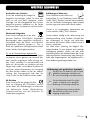
WEITERE HINWEISE
Aufstellen des Gerätes
Die Art der Aufstellung der Anlage hat
klangliche Auswirkungen. Stellen Sie diese deshalb nur auf eine dafür geeignete, stabile
Unterlage. Um das Klangpotential Ihres Systems
optimal auszunutzen, empfehlen wir, die Geräte
auf Vincent Racks zu platzieren und nicht aufeinander zu stellen.
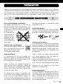
Elektronik Altgeräte
Dieses Gerät unterliegt den in der europäischen Richtlinie 2002/96/EC festgelegten
Bestimmungen, deren gesetzliche Umsetzung in
Deutschland durch das Elektro- und Elektronikgeräte-Gesetz (ElektroG) geregelt ist. Dies ist
durch das Symbol eines durchgestrichenen Abfalleimers auf dem Gerät gekennzeichnet.
Für Sie als Endverbraucher bedeutet das:
Alle nicht mehr verwendeten Elektro- und Elektronik-Altgeräte müssen getrennt vom Hausmüll über
dafür staatlich vorgesehene Stellen entsorgt werden. Damit vermeiden Sie Umweltschäden und
helfen mit, die Hersteller zur Produktion von langlebigen oder wieder verwendbaren Produkten zu
motivieren. Weitere Informationen zur Entsorgung
des alten Gerätes erhalten Sie bei der Stadtverwaltung, dem Entsorgungsamt oder dem Geschäft, in dem Sie das Produkt erworben haben.
CE-Zeichen
Dieses Gerät erfüllt die gültigen EU-Richtlinien zur Erlangung des CE-Zeichens und entspricht damit den Anforderungen an elektrische
und elektronische Geräte (EMV-Richtlinien,
Sicherheitsrichtlinien und den Richtlinien für
Niederspannungsgeräte).
Erklärungen/Hinweise
Dieses Dokument wurde verfasst von
Andreas Böer. Es ist ein Produkt der Sintron Vertriebs
GmbH, 76473 Iffezheim und darf ohne ausdrückliche und schriftliche Genehmigung weder komplett
noch auszugsweise kopiert oder verteilt werden.
Vincent ist ein eingetragenes Warenzeichen der
Sintron Vertriebs GmbH, 76473 Iffezheim.
Vincent arbeitet ständig an der Verbesserung und
Weiterentwicklung seiner Produkte. Deshalb bleiben Änderungen an Design und technischer
Konstruktion des Gerätes, sofern sie dem Fortschritt
dienen, vorbehalten.
Der Inhalt dieser Anleitung hat lediglich Informationscharakter. Er kann jederzeit ohne vorherige
Ankündigung geändert werden und stellt keine
Verpflichtung seitens des Markeninhabers dar. Dieser
übernimmt keinerlei Verantwortung oder Haftung für
Fehler oder Ungenauigkeiten, die möglicherweise in
dieser Bedienungsanleitung enthalten sind.
Erläuterung der grafischen Symbole
Der Blitz weist Sie darauf hin, dass im Gerät
gefährliche Spannungen vorhanden sind,
die einen Stromschlag verursachen können.
Das Ausrufezeichen macht Sie auf besonders wichtige Hinweise bezüglich
Bedienung und Wartung aufmerksam.
Der Zeigefinger kennzeichnet nützliche
Informationen und Hinweise für den
Umgang mit dem Gerät.
Vincent
5
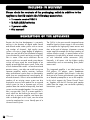
L I E F E R U M FANG
Bitte prüfen Sie den Inhalt der Verpackung, diese sollte zusätzlich zum
Gerät folgendes Zubehör enthalten:
• 1 Fer nbedienung VRC-1
• 2 Batterien vom Typ AAA (LR3)
• 1 Netzkabel
• dieses Handbuch
BESCHREIBUNG DES GERÄTES
Obwohl die Entwicklung stetig in Richtung
digitaler Tonformate und mehrkanaliger AudioVideo-Systeme geht, erfreuen sich hochwertige
Stereoanlagen weiterhin großer Beliebtheit.
Manch einer schreckt auch vor der Installation
allzu aufwändiger Mehrkanalsysteme zurück und
genießt DVD-Filme in Stereo. Manche Musikliebhaber möchten nicht auf Raumklangsysteme
umsteigen, weil High-End-Stereo-Quellen in manchen Surroundsystemen nicht ihr gesamtes
Klangpotential entfalten können. Wer beide
Welten – Surround und Premium-Stereo - miteinander vereinen will, kommt oft um zwei getrennte
Verstärker bzw. Receiver nicht herum, weil viele
Mehrkanalanlagen eher auf Funktionalität als auf
kompromisslose Klangqualität aller Tonkanäle setzen. Sollen die meist schon vorhandenen hochqualitativen Stereolautsprecher auch gleichzeitig
als Frontlautsprecher dienen (damit kein zusätzliches Paar Lautsprecher für vorn notwendig wird),
müssen beide Anlagen miteinander gekoppelt
werden. Dies ist in sehr vielen Fällen nicht möglich. Erst wenn ein Stereoverstärker verwendet
wird, der für einen seiner Eingänge lediglich als
Endverstärker fungiert und für diesen Eingang
somit keine Lautstärkeregelung vornimmt, kann
dieses Stereosystem in bedienfreundlicher Weise
als Teil der Surroundanlage benutzt werden.
6
Vincent
Der SV-234 ist der vielseitigste StereoVollverstärker aus dem Programm von Vincent. Er
kann gleichzeitig hochwertigen Stereo-Quellen als
Verstärker dienen und auf Knopfdruck zu einer
Stereo-Endstufe werden (zum Beispiel für die
Frontlautsprecher eines Heimkinosystems). Eine
Besonderheit ist die Möglichkeit, eine Stereoquelle mit symmetrischen Ausgängen (XLR) anschließen zu können. Höchste Verarbeitungsqualität und ein hervorragendes Preis-LeistungsVerhältnis sind selbstverständlich.
Dieser Vollverstärker ist ein idealer Partner für
DVD-Player, CD-Player, Tuner, Kopfhörerverstärker
und Lautsprecher von Vincent. Er kann auch in
eine Vincent-Mehrkanalanlage basierend auf
Decodervorstufe/Endstufen oder einem AVVerstärker eingebunden werden. Zu diesem
Zweck unterstützt er die Einschaltsteuerungsfunktion („Power Control“). Zusammen mit den
HiFi-Möbeln und Lautsprecherkabeln des Sortiments kann ein perfekt harmonierendes System
aufgebaut werden.
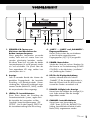
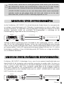
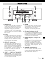
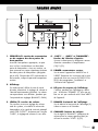
VORDERANSICHT
1
2
4
3
5
6
7
8
1. SPEAKER A/B: Tasten zum
Aktivieren und Abschalten der
beiden Lautsprecherpaare
Wenn geeignete Lautsprecher verwendet
werden, kann auch ein zweites Paar Lautsprecher gleichzeitig betrieben werden.
Mit diesen Tasten lässt sich jedes der beiden
Lautsprecherpaare (A und B genannt) einzeln
ein- und ausschalten. Die jeweils über der
Taste angeordnete LED zeigt, welches Lautsprecherpaar aktiv ist.
4. „LINE1“ … „LINE5“ und „BALANCED“:
Eingangswahltasten
Hiermit wird zwischen den verschiedenen
an den Verstärker angeschlossenen
Eingangsquellen (10)(11)(12) ausgewählt.
2. Anzeige
Stellt im normalen Betrieb den Namen des
gewählten Eingangskanals, die Lautstärkeeinstellung und Betriebszustände (Stummschaltung) dar. Während Einstellungen vorgenommen werden (BALANCE, GAIN), werden
die entsprechenden Werte angezeigt.
6. LED für die Displayabschaltung
Leuchtet, während durch die Funktion
„DIMMER“ (7) die Anzeige abgeschaltet ist,
damit der Zustand nicht mit dem Ausschaltzustand des Gerätes verwechselt wird.
3. LEVEL/: Lautstärketasten
Diese Tasten dienen der Einstellung der
Gesamtlautstärke des Systems, regeln somit
die Lautstärke der Lautsprecher und das
Signal des Stereo-Vorstufenausgangs „PRE
OUTPUT“. Nur für den Eingang „LINE5“ hat
die Lautstärkeeinstellung keine Auswirkung.
5. POWER: Netzschalter
Schaltet das Gerät ein und aus. Beachten Sie
die Hinweise zur Einschaltsteuerung (POWER
CONTROL) in den Abschnitten „Installation“
und „Bedienung des Gerätes“.
7. DIMMER: Helligkeit der Anzeige
Hiermit kann die Helligkeit der Anzeige (2) in
zwei Stufen reduziert oder die Anzeige
abgeschaltet werden.
8. CHANNEL: Lautstärkebalance
Hiermit kann unter Verwendung der
„LEVEL“-Tasten (3)(19) die „BALANCE“-Einstellung (Lautstärkeunterschied der Kanäle
Rechts/Links) vorgenommen werden.
Vincent
7
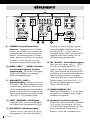
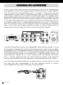
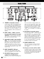
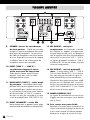
RÜCKANSICHT
9
10
13
12
14
9.
15
SPEAKER: Lautsprecheranschlussklemmen Ausgangsbuchsen mit Schraubklemmen zum Anschluss von einem oder zwei
Lautsprecherpaaren. Es können Lautsprecherkabel mit 4 mm Bananensteckern verwendet
werden. Beachten Sie die Hinweise im Kapitel
„Installation“ für den Fall, dass zwei Lautsprecherpaare angeschlossen werden sollen.
10. INPUT („LINE1“ ... „LINE4“): Anschluss
von Stereo-Quellgeräten mit Hochpegelausgang Vier Stereo-Cinch-Eingangsanschlüsse für Quellgeräte mit analogem
Stereoton-Hochpegelausgang.
11. MAIN INPUT („LINE5“):
Endstufeneingang Anschluss eines StereoVorverstärkers oder eines Quellgerätes mit Vorverstärkerausgang. Beachten Sie, dass an „LINE5“
kein Hochpegelausgang einer Stereo-Quelle angeschlossen werden darf. Der Eingang darf auch
nicht mit dem benachbarten Vorverstärkerausgang
„PRE OUTPUT“ (14) verbunden werden.
12. INPUT „BALANCED“: XLR-Eingang
Eingangsanschluss für ein Stereo-Quellgerät
mit symmetrischem Ausgangsanschluss (XLR).
13. REC OUTPUT: Aufnahmeausgang
Schließen Sie hier, wenn gewünscht, z.B. ein
Aufnahmegerät an. Das Stereo-Signal dieses
8
Vincent
11
16
Ausganges ist mit dem Ausgangssignal der
momentan gewählten Quelle an einem der
Anschlüsse „LINE1“... „LINE4“ identisch.
Die Signale der an „LINE5“ und „BALANCED“
angeschlossenen Geräte werden nicht zum
Aufnahmeausgang durchgeschleift.
14. PRE OUTPUT: Vorverstärkerausgang
Wenn einer der Eingänge „LINE1“ ... „LINE4“
(10) oder der Eingang „BALANCED“ (12)
gewählt ist, kann dieser Ausgang das vorverstärkte Stereo-Tonsignal der momentan gewählten Quelle an zwei zusätzliche Endstufenkanäle
oder einen aktiven Subwoofer weitergeben.
Der Ausgang darf nicht mit dem benachbarten
Endstufeneingang „LINE5 MAIN INPUT“ (11)
oder dem Hochpegeleingang eines anderen
Gerätes verbunden werden.
15. POWER CONTROL (12V)
Über diese Klinkenbuchsen (3,5 mm) werden
die Signale zur Einschaltsteuerung (Trigger)
empfangen und gesendet.
16. Netzbuchse mit Sicherungshalter
Bringen Sie hier das Netzkabel an und verbinden
Sie es mit der Stromversorgung. Das kleine
Kunststoff-Gehäuse an der Unterseite der Netzbuchse beinhaltet die Gerätesicherung.
Beachten Sie dazu die Sicherheitshinweise.
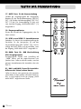
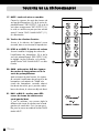
FERNBEDIENUNG
Richten Sie die Fernbedienung mit deren Vorderseite direkt auf die Gerätefront, zwischen Fernbedienung und Gerät dürfen sich keine Gegenstände befinden.
Achten Sie darauf dass Sie die Fernbedienung nicht
schräg auf das Gerät richten, außerhalb eines
Winkels von ±30° zur Mittelachse reagiert das Gerät
eventuell schlechter auf Bedienversuche.
Der Abstand zwischen Fernbedienung und Gerät
sollte nicht mehr als 7 m betragen, außerhalb dieser
Reichweite nimmt die Zuverlässigkeit der Fernbedienung ab.
Tauschen Sie beide Batterien wenn der Abstand zum
Gerät in dem die Fernbedienung benutzt werden
kann, sich verringert.
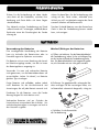
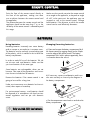
B AT T E R I E N
Verwendung der Batterien
Eine unsachgemäße Handhabung der Batterien
kann ein Auslaufen der Batteriesäure oder im
Extremfall sogar eine Explosion verursachen.
Die Batterien müssen unter Beachtung der korrekten Polarität eingelegt werden, wie dies im Innern
des Batteriegehäuses angezeigt ist.
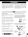
Wechsel/Einlegen der Batterien:
a) Öffnen und entfernen Sie den Batteriefachdeckel
der Fernbedienung, indem Sie ihn mit kräftigem Zug
an der Lasche am Rand der Fernbedienung anheben. Der Batteriefachdeckel wird magnetisch gehalten, die Schrauben müssen nicht gelöst werden!
a
Verwenden Sie neue und verbrauchte Batterien
nicht gemeinsam, um die Batterielebensdauer voll
auszuschöpfen. Achten Sie darauf, nur Batterien
gleichen Typs einzulegen.
Einige Batterien sind aufladbar, andere jedoch
nicht. Beachten Sie die Vorsichtshinweise und
Anweisungen, die auf jeder Batterie vermerkt sind.
Entnehmen Sie die Batterien, wenn die Fernbedienung längere Zeit nicht benutzt wird.
b) Entfernen Sie gegebenenfalls verbrauchte Batterien und legen Sie die neuwertigen Zellen, wie
im Batteriefach schematisch dargestellt, richtig ein.
Alt
Neu
b
Verbrauchte Batterien sind aus Gründen des
Umweltschutzes entsprechend der örtlichen Umweltschutzbestimmungen zu entsorgen und nicht in
den Hausmüll zu geben.
c) Schließen Sie das Batteriefach
der Fernbedienung.
c
Ver wenden Sie ausschließlich
Mikrozellen der Größe AAA (LR3)
Vincent
9
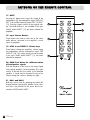
TA S T E N D E R F E R N B E D I E N U N G
17. MUTE: Taste für die Stummschaltung
Schaltet die Ausgangssignale der Lautsprecherklemmen (9), des Vorverstärkerausgangs „PRE OUTPUT“ (14) und des Aufnahmeausgangs „REC OUTPUT” (13) ab. Die Stummschaltung ist nicht wirksam, wenn der Eingang „LINE5 MAIN INPUT“ (11)
ausgewählt ist.
18. Eingangswahltasten
Dienen der Auswahl des Eingangsgerätes, das Sie
hören möchten.
17
21
18
19. LEVEL und LEVEL : Lautstärketasten
Verändern Sie hiermit die Lautstärkeeinstellung des
Verstärkers für die Lautsprecher (9) und den
Vorverstärkerausgang (PRE OUTPUT (14)). Die Einstellung hat keinen Einfluss auf die Lautstärke, wenn
der Eingang „LINE5 MAIN INPUT“ ausgewählt ist.
19
20. GAIN: Taste für -8dB Abschwächung
aller Ausgangssignale
Ausgangssignale werden nach Umstellung auf
„-08dB“ kleiner und die angeschlossenen Lautsprecher leiser. Sollte nur aktiviert werden, wenn bei
geringen Lautstärkewerten die Lautstärke schon sehr
hoch ist.
21. BAL L und BAL R: Tasten für Lautstärkedifferenz des linken/rechten Kanals
Stellen Sie hiermit, wenn gewünscht, den Lautstärkeunterschied zwischen rechtem und linkem Kanal ein.
Dies ist nicht möglich für die am Eingang „LINE5
MAIN INPUT“ angeschlossene Quelle.
10
Vincent
20
I N S TA L L AT I O N
Stellen Sie die Kabelverbindung in der nachfolgend genannten Reihenfolge her. Bringen Sie erst zuletzt das
Netzkabel an und verbinden es mit der Steckdose. Zwei Lautsprecher, ein oder mehrerer Quellgeräte sowie
das Netzkabel sind in jedem Fall anzuschließen. Die Kabel für die Einschaltsteuerung, zum Aufnahmegerät
oder zu einer weiteren Stereo-Endstufe müssen nur angeschlossen werden, wenn sie benötigt werden.
ZUR BESONDEREN BEACHTUNG
Keine Vor-End-Brücke erforderlich
Der Eingang „LINE5 MAIN IN“ (11) darf nicht mit
dem benachbarten Vorverstärkerausgang „PRE
OUTPUT“ (14) verbunden werden. Der integrierte
Vorverstärker ist intern mit dem Endverstärker verbunden. Es kann
kein Gerät unter Verwendung dieser Anschlüsse zwischen
integrierte Vor- und
Endstufe geschaltet
werden (Effektschleife,
effects loop)!
Entfernen der Schutzkappen
Vor der ersten Installation müssen von
allen verwendeten Anschlüssen an der
Geräterückseite die KunststoffSchutzkappen entfernt werden.
1
2
O UT PUTO U
Cinch-Anschlüsse
Als Steckverbinder für Ein- und Ausgänge sind
mechanisch identische Cinch-Buchsen vorhanden.
Achten Sie darauf, dass Sie diese Anschlüsse bei
der Installation nicht verwechseln!
Achten Sie darauf, die analogen Eingänge für
rechts und links nicht zu vertauschen. Häufig sind
deren Cinch-Anschlüsse folgendermaßen farblich
markiert: Rot für den rechten Kanal, schwarz oder
weiß für den linken Kanal.
Das Berühren des mittleren Kontaktstiftes des
Cinch-Steckers mit dem äußeren Kontakt der CinchBuchse kann bei eingeschalteten Geräten im
schlimmsten Fall zur Beschädigung der Geräte führen. Nehmen Sie deshalb niemals Änderungen an
den Kabelverbindungen vor, während die Geräte
eingeschaltet sind!
Steckverbindungen
Achten Sie darauf, dass alle Steckverbindungen
fest sitzen. Unzureichende Anschlüsse können Störgeräusche, Ausfälle und Fehlfunktionen verursachen.
- Falsch -
- Richtig -
Lautsprecheranschluss
Es ist empfehlenswert, konfektionierte Lautsprecherkabel zu verwenden, anstatt die Innenleiter (Litze)
der Kabel direkt anzuklemmen. Bananenstecker oder
Kabelschuhe bieten höhere Sicherheit gegen Kurzschlüsse und Beschädigung der Lautsprecher oder
des Verstärkers.
Sorgen Sie dafür, dass blanke Lautsprecherdrähte
sich niemals gegenseitig oder das Metall der
Gehäuserückwand berühren können!
Achten Sie auf korrekten Anschluss der positiven und
negativen Lautsprecherdrähte. Vertauschter Anschluss
macht sich durch verringerte Klangqualität bemerkbar.
Verwenden Sie nur Lautsprecher mit einer Nennimpedanz von mindestens 4Ω.
Kabelverbindungen
Um das Klangpotential der Komponenten voll auszuschöpfen, sollten nur hochwertige Lautsprecherund Verbindungskabel, beispielsweise Vincent
Kabel, verwendet werden. Bevorzugen Sie geschirmte Audio-Kabel. Ihr Fachhändler wird Sie
gern diesbezüglich beraten.
Vincent
11
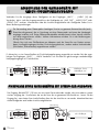
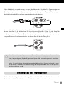
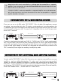
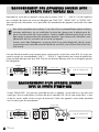
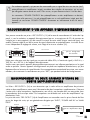
ANSCHLUSS DER QUELLGERÄTE MIT
CINCH-HOCHPEGELAUSGANG
Verbinden Sie die Ausgänge dieser Quellgeräte mit den Eingängen „LINE1“ ... „LINE4“ (10) des
Verstärkers. Meist sind die Ausgangsanschlüsse der Quellgeräte mit „LINE OUT“, „AUDIO OUT“ oder
„FRONT OUT“ markiert. Informationen über die Anschlussmöglichkeiten der Quellgeräte finden Sie in
deren Bedienungsanleitungen.
Zur Verwendung eines Plattenspielers benötigen Sie eine so genannte Entzerrer-Vorstufe (auch
Phono-Vorstufe genannt), die im Signalweg zwischen Plattenspieler und einem der Hochpegeleingänge installiert wird. Einige Plattenspieler-Modelle enthalten bereits diese Vorstufe und können direkt angeschlossen werden. Weitere Informationen erhalten Sie in der Bedienungsanleitung dieses Gerätes.
Oftmals lässt sich unter Zuhilfenahme von Adaptern auch der Stereo-Ton von Geräten nutzen,
deren Line-Pegel-Ausgänge nicht über Cinch-Ausgangsbuchsen, sondern andere Steckverbinder
(DIN-Stecker, Klinkenstecker) angeschlossen werden.
Es können bis zu vier Stereo-Quellen mit Cinch-Hochpegelausgang angeschlossen werden. Bei den zugehörigen Ton-Eingängen „LINE1“ ... „LINE4“ handelt es sch um elektrisch gleichwertige standardmäßige
Hochpegeleingänge mit Cinch-Buchsen.
SV-234
Cinch-Verbindung
CD-Player, Tuner,
DVD-Player, etc.
LINE OUT
ANSCHLUSS EINES QUELLGERÄTES MIT STEREO-XLR-AUSGANG
Der Eingang „BALANCED“ (12) kann nur mit einem Gerät verbunden werden, das einen ebenso symmetrischen Ausgang hat. Sie erkennen das an der Form des so genannten XLR-Anschlusses. Lassen Sie den
Eingang frei, wenn keines Ihrer Audio-Quellen diese Art des Anschlusses verwendet. Manchmal besitzen
Audio-Quellgeräte auch beide Anschlussmöglichkeiten.
XLR-Verbindung
SV-234
z.B. CD-Player
12
Vincent
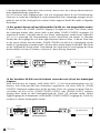
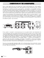
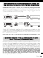
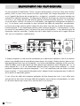
ANSCHLUSS EINES STEREO-VOR VERSTÄRKERS ODER
DER FRONTKANÄLE EINES MEHRKANALSYSTEMS
Dieser Stereovollverstärker ist mit einem Eingangsanschluss („LINE5“) versehen, dessen Signal die Vorstufe
umgeht (so genannter „unity gain“-Eingang). Dadurch kann dieser mit dem Vorverstärkerausgang eines
anderen Gerätes oder den Vorverstärkerausgängen für die Frontkanäle eines Heimkinosystems (AVReceiver oder AV-Vorstufe) verbunden werden. Für die Lautstärkeregelung sowie die Funktion von BALANCE und Stummschaltung (MUTE) ist dann der angeschlossene Vorverstärker zuständig.
SV-234
Cinch-Verbindung
PRE
Stereo-Vorverstärker
OUTPUT
SV-234
Cinch-Verbindung
z.B. AV-Vorverstärker
ANALOG
AUDIO OUTPUT
Ist der Eingang „LINE5“ gewählt, verhält sich der Verstärker SV-234 wie eine Stereo-Endstufe. Wenn sich
der Verstärker SV-234 beim Betrieb als Endstufe automatisch mit dem Vorverstärker ausschalten soll, müssen
die nachfolgend beschriebenen Kabelverbindungen für die Einschaltsteuerung richtig vorgenommen werden.
Lassen Sie den Eingang „LINE5“ frei, wenn Sie den Verstärker SV-234 nicht als Endstufe nutzen wollen.
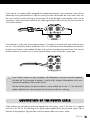
KABELV E R B I N D U N G E N F Ü R D I E
E I N S C H A LT S T E U E R U N G ( P O W E R C O N T R O L )
Viele AV-Systeme bestehen aus einer Vielzahl von Einzelkomponenten. Um diese nicht vor und nach jedem
Gebrauch alle einzeln aus- und einzuschalten, haben manche Hersteller die Geräte mit einer so genannten „TRIGGER“-Schaltung, auch „Power Control“ oder „Einschaltsteuerung“ genannt, ausgestattet. Vor
allem für Vor- und Endstufen wird diese Art der ferngesteuerten Standby-Schaltung verwendet. Um diese
verwenden zu können, müssen Kabelverbindungen direkt oder indirekt zwischen dem Vollverstärker und
allen Geräten, welche diese Funktion unterstützen, hergestellt werden. Die Funktion „POWER CONTROL“
bewirkt, dass jedes Ein- bzw. Ausschalten eines Gerätes des Systems (üblicherweise des Vorverstärkers)
automatisch das Ein-/Ausschalten aller daran angeschlossenen Geräte, die diese Funktion unterstützen,
bewirkt. Beachten Sie, dass alle Geräte, welche auf die Einschaltsteuerung reagieren, im
Ausschaltzustand nicht vom Netz getrennt, sondern in Bereitschaft geschaltet sind. Als Verbindungskabel
finden zweiadrige, mit 3,5 mm Klinkenstecker (mono) versehene Leitungen Verwendung. Für die
Verbindung zwischen jeweils zwei Geräten wird eins dieser Kabel benötigt.
Vincent
13
Ist die hier beschriebene Arbeitsweise nicht erwünscht, reicht es meist, die in diesem Abschnitt beschriebenen Kabelverbindungen wegzulassen.
Der SV-234 besitzt einen Eingangsanschluss und zwei Ausgangsanschlüsse für die Einschaltsteuerung.
Damit kann er sowohl das Schaltsignal für weitere Komponenten einer Stereoanlage erzeugen und ausgeben als auch auf das Schaltsignal eines anderen Gerätes reagieren. Beide Fälle werden im Folgenden
beschrieben.
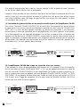
(1) Das gesamte System soll am Vollverstärker SV-234 ein- und ausgeschaltet werden
In diesem Fall muss der „POWER CONTROL“-Eingang (15) freigelassen werden. Zwei Geräte, welche
das Schaltsignal erhalten sollen, können direkt an den beiden „POWER CONTROL“-Ausgängen (15)
angeschlossen werden. Sind jedoch mehr als zwei Geräte, welche gesteuert werden können, angeschlossen, so ist es notwendig, die Steuerverbindung zwischen Vorverstärker und weiteren zu steuernden
Geräten über die Ausgänge der zwei direkt angeschlossenen Geräte zu führen. Zu diesem Zweck kann
an den meisten Geräten einer der beiden „POWER CONTROL“-Anschlüsse als Signaleingang und der
andere als Signalausgang verwendet werden. Auf diese Weise können theoretisch unendlich viele Geräte
mit den Schaltimpulsen versorgt werden. Diese Methode, das Signal durch Ein- und Ausgänge der Geräte
durchzuschleifen und somit zu verketten, wird auch als „daisy chaining“ bezeichnet.
SV-234
z.B. Endverstärker
(2) Der Verstärker SV-234 wird als Endstufe verwendet und soll auf das Schaltsignal
reagieren
Wenn beispielsweise am Eingang „LINE5 MAIN INPUT“ (11) die Vorverstärkerausgänge eines AVReceivers, einer AV-Vorstufe oder eines AV-Verstärkers angeschlossen sind, dieses Gerät ein „POWER
CONTROL“-Schaltsignal ausgeben kann und der Verstärker SV-234 sich synchron mit diesem Gerät ein/ausschalten soll, muss ein mit „POWER CONTROL OUTPUT“ oder „TRIGGER OUTPUT“ markierter
Ausgang dieses Geräte mit dem Schaltsignaleingang des SV-234 (15) verbunden werden. Weitere
Trigger-Ausgänge der AV-Komponente und die beiden „POWER CONTROL“-Ausgänge des SV-234 können dann zu weiteren Geräten geführt werden.
SV-234
z.B. AV-Vorstufe
14
Vincent
Viele der Geräte, welche durch ein Schaltsignal gesteuert werden können (nicht Vorverstärker
oder Vollverstärker), besitzen zwei Anschlussbuchsen, welche nicht als Ein- oder Ausgang
gekennzeichnet sind. In diesem Fall kann einer der beiden beliebig gewählt werden.
„POWER CONTROL“-Anschlüsse von Vor- oder Vollverstärkern dürfen niemals untereinander
verbunden werden! An alle anderen Geräte darf direkt oder indirekt nur ein Vor- oder
Vollverstärker über „POWER CONTROL“-Verbindung angeschlossen sein!
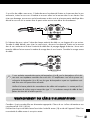
ANSCHLUSS EINES AUFNAHMEGERÄTES
An die Cinch-Buchsen „REC OUTPUT“ (13) auf der Rückseite des Gerätes können Sie, wenn gewünscht,
ein analoges Stereo-Aufnahmegerät (z.B. CD-Recorder, Kassettenrecorder o.ä.) oder ein anderes Gerät,
das den unveränderten, fest eingestellten Stereo-Ausgangspegel (Line-Pegel) der momentan am Verstärker
gewählten Signalquelle erhalten soll, anschließen. Der Ausgangspegel ist unabhängig von der
Lautstärkeregelung, reagiert aber auf die Stummschaltung (17).
SV-234
Cinch-Verbindung
z.B. Kassettenrecorder
LINE IN
Verbinden Sie diesen Signalausgang mittels Cinch-Kabel mit dem Signaleingang („LINE IN“, „TAPE IN“
oder „REC IN“) des Aufnahmegerätes. Beachten Sie bitte, dass einige Aufnahmegeräte einen störenden
Einfluss auf das jeweilige Audiosignal haben können. Manche Aufnahmegeräte haben eine eher niedrige Eingangsimpedanz, welche die Eingangssignalspannung geringfügig verfälschen kann. Für maximalen Musikgenuss empfehlen wir Ihnen, die Verbindung an den „REC“-Buchsen nur so lange anzuschließen,
wie Sie Aufnahmen durchführen.
ANSCHLUSS ZWEIER ZUSÄTZLICHER ENDSTUFENKANÄLE
Die Buchsen „PRE OUTPUT“ (14) benötigen Sie nur, wenn Sie eine separate Stereo-Endstufe oder zwei
Mono-Endstufen für die Versorgung zweier zusätzlicher Lautsprecher verwenden wollen. Dies kann sinnvoll sein, wenn zwei weitere Lautsprecher für Stereo-Musikwiedergabe, eventuell auch in einem anderen
Raum, verwendet werden sollen. Diese Lautsprecher werden dann an die Ausgänge zusätzlicher
Endverstärker angeschlossen. Die Ausgangsanschlüsse „PRE OUTPUT“ (14) des Verstärkers werden mit
den Eingangsanschlüssen der Endstufe(n), welche meist mit „INPUT“, „POWER AMP IN“ oder „MAIN
INPUT“ beschriftet sind, verbunden.
SV-234
Cinch-Verbindung
MAIN
z.B. Stereo-Endverstärker
INPUT
Vincent
15
ANSCHLUSS DER LAUTSPRECHER
An den Verstärker SV-234 können entweder ein Lautsprecherpaar (A) oder auch zwei Lautsprecherpaare
(A+B) angeschlossen werden. Beide Ausgänge bekommen dasselbe Stereosignal. Für jeden Lautsprecher
finden Sie am Gerät zwei Lautsprecherklemmen (positiv + und negativ -), welche mit einer Seite eines
Lautsprecherkabels verbunden werden. An jedem Klemmenpaar finden Sie eine Beschriftung (R oder L),
welche anzeigt, zu welcher Seite (rechts oder links) das Klemmenpaar gehört. Am Lautsprecher gibt es
gleichartige oder ähnliche Anschlüsse, auch hier ist markiert, welcher Anschluss zu welchem Pol (+ oder
-) gehört. Hier wird das andere Ende des dem Lautsprecher zugeordneten Lautsprecherkabels angeschlossen. Durch das Lautsprecherkabel müssen jeweils gleichartige Anschlüsse eines Klemmenpaares miteinander verbunden werden: die mit „+“ markierte Klemme am Verstärker muss zum mit „+“ markierten Anschluss des Lautsprechers führen. Die Skizze zeigt die Anschlüsse bei Verwendung eines Lautsprecherpaares. Soll ein zweites Lautsprecherpaar angeschlossen werden, so werden auf ähnliche Weise die
Klemmen der unteren Anschlussreihe („B“) mit den zusätzlichen Lautsprechern verbunden.
SV-234
Wird jeder Lautsprecher ganz normal mit einem doppeladrigen Lautsprecherkabel verbunden, so müssen
bei Lautsprechern mit Doppelanschluss (vier Lautsprecherklemmen) die (meist mit den Lautsprechern gelieferten) Kontaktbrücken (meist kleine Metallplättchen oder kurze Kabelstückchen) jeweils zwischen den beiden
Klemmen gleicher Polung (z.B. beide mit „+“ beschriftete Klemmen) angebracht werden. Der mit „+“ und
„R“ markierte Anschluss des Verstärkers wird mit einem der mit „+“ markierten, gebrückten Anschlüsse des
rechten Lautsprechers verbunden. Der mit „-“ und „R“ markierte Anschluss des Verstärkers wird mit einem
der mit „-“ markierten, gebrückten Anschlüsse des rechten Lautsprechers verbunden. Für das Lautsprecherkabel zwischen den Anschlüssen des linken Lautsprechers ist die entsprechende Zuordnung zu wählen.
Wenn Sie konfektionierte Lautsprecherkabel mit 4 mm Bananensteckern verwenden, brauchen Sie nur die
zwei Stecker eines jeden Lautsprecherkabels mit den zwei zugehörigen Klemmen zu verbinden.
Die Schraubkappe der Klemme sollte im Uhrzeigersinn festgedreht werden.
16
Vincent
Sollen Kabelschuhe verwendet werden, muss an jeder Klemme der Schraubkopf im Gegenuhrzeigersinn
gelöst, der Kabelschuh daruntergeschoben und die Schraubkappe im Uhrzeigersinn festgedreht werden.
Stellen Sie zur Vermeidung von Schäden sicher, dass der Anschluss fest sitzt und kein blankes Metall von
den Kabelschuhen die Rückwand oder einen anderen Anschluss berührt.
Anderenfalls entfernen Sie ein ca. 1 cm langes Stück der Isolierung von jedem Endstück des Lautsprecherdrahtes. Verdrillen Sie die blanke Litze, um Kurzschlüsse zu vermeiden. Drehen Sie den Knopf der
Lautsprecherklemme im Gegenuhrzeigersinn, um ihn zu lösen und führen Sie das blanke Drahtende in das
nun freiliegende Klemmenloch ein. Drehen Sie den Knopf nun im Uhrzeigersinn, um den Draht in der
Lautsprecherklemme festzuklemmen. Achten Sie darauf, dass die Verschraubung fest ist.
Wenn Sie zwei Lautsprecherpaare (A und B) anschließen möchten, müssen alle verwendeten
Lautsprecher eine Nennimpedanz von mindestens 8Ω aufweisen. Wird der Verstärker nur mit
einem Lautsprecherpaar (A oder B) betrieben, können alle Lautsprechertypen mit einer Nennimpedanz von mindestens 4Ω angeschlossen werden.
Achten Sie auf die richtige Polung der Lautsprecherkabelanschlüsse. Der positive Kontakt ist meist
rot und oft mit „+“ markiert. Die markierte Leitung des Lautsprecherkabels muss mit dem positiven
Anschluss verbunden werden.
ANSCHLUSS DES NETZKABELS
Drücken Sie den Kaltgerätestecker des mitgelieferten Netzkabels fest in die Netzbuchse an der
Geräterückwand. Verbinden Sie das andere Ende des Netzkabels mit einer Netzsteckdose.
Vincent
17
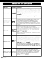
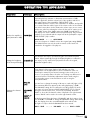
BEDIENUNG DES GERÄTES
Aktion
Ein- und Ausschalten
Taste(n)
POWER (5)
Beschreibung
Das Gerät wird an der Gerätevorderseite ein- und ausgeschaltet.
Ist der Schalter in der Ausschaltposition, ist das Gerät jedoch nicht
vollständig vom Stromnetz getrennt und reagiert auf ein am Eingang
„POWER CONTROL INPUT“ (15) anliegendes Signal. Das Gerät kann
somit nicht ausgeschaltet werden, solange ein an diesem Eingang
angeschlossenes Gerät ein Einschaltsignal ausgibt.
WELCOME
Direkt nach dem Einschalten sollte vorsichtshalber die
Lautstärkeeinstellung des Verstärkers reduziert werden.
Lautsprecherpaare
einzeln ein- oder
ausschalten
Eingangsquelle
wählen
SPEAKER
A/B (1)
Eingangswahltasten
(10)(11)(12)
Zur Wiedergabe von Musik über Lautsprecher muss mindestens ein
Paar Lautsprecherpaar angeschlossen sein (zweckmäßigerweise an
den Anschlüssen „A“). Die verwendeten Anschlüsse müssen unter
Verwendung der Tasten „SPEAKER“ aktiviert sein (LED leuchtet).
Nur wenn zwei Lautsprecherpaare betrieben werden, ist es notwendig
auch den zweiten Anschluss zu aktivieren.
Kurzes Betätigen der Taste für den gewünschten Eingangskanal
(LINE1... LINE5 oder BALANCED) wechselt auf die Wiedergabe des
dort angeschlossenen Gerätes. Sowohl die Gerätevorderseite als auch
die Fernbedienung tragen diese Wahltasten. Der Name des Eingangskanals erscheint in der Anzeige.
LINE2
→
LINE2 -45dB
Vor dem Umschalten des Eingangskanals sollte vorsichtshalber die
Lautstärke (3)(19) reduziert werden!
Lautstärke des
Systems verändern
LEVEL/
(3)(19)
Halten Sie die Taste „LEVEL“ gedrückt, um die Lautstärke zu erhöhen.
Verwenden Sie „LEVEL“, um diese zu verringern. Dies ist sowohl mit der
Fernbedienung als auch mit den Gerätetasten möglich. Das Display (2)
zeigt die aktuelle Lautstärkeeinstellung an. Der Wert für das Lautstärkeminimum ist -99dB, das Maximum wird spätestens bei einer Anzeige von
00dB, mit den meisten Lautsprechern schon viel früher erreicht.
LINE2 -99dB
← ... →
LINE2 00dB
Der Lautstärkewert kann nicht verändert werden, während der Eingang
„LINE5 MAIN IN“ gewählt ist. In der Anzeige (2) ist dann der Schriftzug
„MAX“ zu sehen. Die Lautstärkeeinstellung hat keinen Einfluss auf das
Signal am Ausgang „REC OUTPUT“ (13).
Lautsprecher und
Vorstufenausgang
stummschalten
MUTE (17)
Die Stummschaltung kann nur über die Fernbedienung betätigt werden.
Sie schaltet das Ausgangssignal der Lautsprecheranschlüsse (9), des Vorverstärkerausgangs „PRE OUTPUT“ (14) sowie des Aufnahmeausgangs
„REC OUTPUT“ (13) ab. Durch erneutes Betätigen wird die ursprünglich
eingestellte Lautstärke wiederhergestellt. Solange die Stummschaltung
aktiv ist, ist in der Anzeige der Schriftzug „MUTING“ zu sehen.
MUTING
18
Vincent
← ... →
MUTE OFF
BEDIENUNG DES GERÄTES
Aktion
Taste(n)
Beschreibung
Betätigen dieser Taste aktiviert bzw. deaktiviert eine Pegeldämpfung um
8dB, welche sich sowohl auf die Lautstärke der Lautsprecher als auch
die Signale des Ausgangs „PRE OUTPUT“ (14) auswirkt. Die GAINEinstellung ist sinnvoll, wenn die Kombination aus Verstärker und Lautsprechern eine so hohe Empfindlichkeit zeigt, dass der nutzbare Regelbereich der Lautstärkeeinstellung des SV-234 bei niedrigen Werten liegt.
Dann ist bei geringen Lautstärkewerten die Lautstärke schon sehr hoch
und die Lautstärkeschritte sind zu grob.
Verstärkung reduzieren
(-8dB Pegeldämpfung)
GAIN (20)
Drücken Sie in diesem Fall, nachdem Sie die Lautstärke vorsichtshalber
reduziert haben, die Taste „GAIN“. Falls die Pegeldämpfung vorher
abgeschaltet war, erscheint nun „-08dB“ in der Anzeige. Die Lautstärke
wird geringer und die Pegel der Ausgangssignale „PRE OUTPUT“ (14)
und “REC OUTPUT“ (13) werden kleiner.
GAIN -08dB
← ... →
GAIN -00dB
Ein weiterer Tastendruck bringt die Verstärkung wieder in den
ursprünglichen Zustand (00dB). Die GAIN-Funktion kann nur über
die Fernbedienung ein- und ausgeschaltet werden. Im täglichen
Gebrauch der Vorstufe sollte diese Taste nicht betätigt werden!
Helligkeit der
Anzeige an der
Gerätefront
verändern
DIMMER (7)
BAL L/R
(21)
Kanalbalance
verändern
CHANNEL
(8)
LEVEL/
(3)(19)
Diese Funktion kann nur mit der Taste an der Gerätevorderseite betätigt
werden. Mit dieser Taste kann die Helligkeit der Anzeige (2) an der
Gerätevorderseite in zwei Stufen reduziert (Betätigung 1x, 2x) oder die
Anzeige abgeschaltet (Betätigung 3x) werden. Ein vierter Tastendruck
stellt die ursprüngliche, maximale Helligkeit wieder her.
Hiermit stellen Sie einen der beiden Kanäle und somit auch einen der
beiden Lautsprecher lauter als den anderen ein. Die Kanalbalance-Regelung kann sowohl über die Fernbedienung als auch an der Gerätevorderseite vorgenommen werden. Das ist evtl. gewünscht, falls Sie am
Hörplatz dem einen der beiden Lautsprecher näher als dem anderen
sind und dadurch ein Lautstärkeunterschied wahrgenommen wird.
Sie können diese Kanalungleichheit um 10 Stufen jeweils nach rechts
bzw. links verstellen. Der maximale Wert der Kanalungleichheit wird mit
+10dB erreicht. Die Einstellung wirkt sich nicht auf den Ausgang „REC
OUTPUT“ (13) aus und ist auch nicht möglich für das am Eingang
„LINE5 MAIN INPUT“ (11) angeschlossene Gerät.
Mit der Fernbedienung: Betätigen Sie, gegebenenfalls mehrfach, die
Taste „BAL L“, um den linken Kanal lauter als den rechten Kanal einzustellen. Verwenden Sie die Taste „BAL R“, um den rechten Kanal
lauter als den linken Kanal einzustellen.
An der Gerätevorderseite: Drücken Sie die Taste „CHANNEL“.
Nun haben Sie die Möglichkeit, mit den „LEVEL“-Tasten (3)(19) die Lautstärkebalance zu verändern. Nach kurzer Zeit wird dieser Einstellmodus
wieder verlassen.
Die Anzeige stellt während der Veränderung des eingestellten Wertes
auch dar, welcher der beiden Stereo-Kanäle lauter eingestellt wurde.
BAL L +10dB
← ... →
BAL 00dB
← ... →
BAL R +10dB
Vincent
19
WEITERE TIPPS
Einspielzeit/Aufwärmen
Ihre Audio-Geräte benötigen eine gewisse Zeit bis
sie ihre klangliche Höchstleistung erreichen.
Dieser Zeitraum ist für die verschiedenen Komponenten Ihres Systems sehr unterschiedlich. Bessere
und gleichförmigere Leistung erhalten Sie während der Zeit, die das Gerät eingeschaltet bleibt.
Nutzen Sie die Erfahrung Ihres Fachhändlers!
Netzbrummen
Bestimmte Quellgeräte können im Verbund mit dem
Verstärker zu einem über die Lautsprecher hörbaren Brummgeräusch führen, dessen Lautstärke sich
mit dem Lautstärkeregler beeinflussen lässt. Dies ist
kein Hinweis auf einen Mangel eines Ihrer AudioProdukte, muss aber durch entsprechende Maßnahmen verhindert werden. Generell kann jedes
an den Verstärker angeschlossene, ebenfalls netzbetriebene und mit dem Schutzleiter des Stromnetzes verbundene Gerät dieses Problem hervorrufen.
Dieses Phänomen wird erfahrungsgemäß entweder durch den Antennenanschluss des Tuners bzw.
Fernsehers oder in Verbindung mit Personalcomputern, elektrostatischen Lautsprechern, Subwoofern,
Plattenspielern oder Kopfhörerverstärkern hervorgerufen, sofern eine Audioverbindung zum
Verstärker besteht.
20
Vincent
Eine weitere mögliche Quelle für Brummstörungen
stellt die elektromagnetische Einstrahlung des
Netzteiles anderer Geräte (z.B. Verstärker,
Receiver, CD-Player, Tuner usw.) auf das Tonabnehmersystem eines angeschlossenen Plattenspielers dar. Solche Fehlerursachen kann man
leicht selbst ermitteln, indem man die Aufstellung
des Plattenspielers gegenüber den anderen
Geräten verändert.
Das Massepotential aller Signale ist in fast jedem
elektrischen Gerät an einem zentralen Punkt
zusammengefasst. Dort finden sie genau einmal
eine gemeinsame Verbindung. Sollte ein Schutzleiter vorhanden sein, hat er immer an einer strategisch günstigen Stelle eine unlösbare Verbindung mit dem Gehäuse und beide werden
meist auch genau einmal am zentralen Massepunkt mit angeschlossen. So wird auch die
abschirmende Wirkung des Gehäuses erzeugt.
Manche Geräte besitzen einen Masse-Trennschalter (GND SWITCH) an der Geräterückseite.
Wenn dieser eingeschaltet ist (sich in der Position
„ON befindet“), sind Schutzleiter und Gehäuse
gemeinsam vom Massepunkt abkoppelt, die
Schutzleiterwirkung bleibt erhalten.
Ist das Brummgeräusch durch eigene Versuche
nicht zu beseitigen, wird Ihnen Ihr Fachhändler
weiterhelfen.
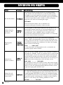
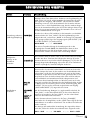
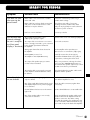
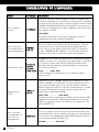
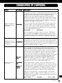
FEHLERSUCHE
Symptom
Mögliche Fehlerursache
Abhilfe
Keine Funktion nach
Betätigung des
Netzschalters
Netzkabel nicht an eine betriebsbereite
Steckdose angeschlossen.
Stellen Sie eine Verbindung zu einer
funktionierenden Steckdose her.
Netzkabel nicht fest in die Steckdose und
die Gerätebuchse gesteckt oder defekt.
Prüfen Sie das Netzkabel, tauschen Sie es
gegebenenfalls gegen ein geeignetes Kaltgerätekabel aus und drücken Sie dessen
Stecker fest in die Steckdose und auf der
anderen Seite in die Netzbuchse des Gerätes.
Gerätesicherung bzw. Gerät defekt.
Kontaktieren Sie Ihren Fachhändler.
Das momentan eingestellte (10)(11)(12)
Quellgerät gibt kein Signal aus.
Starten Sie die Wiedergabe der angeschlossenen Signalquelle.
Ausgang des Quellgerätes nicht oder falsch
bzw. nicht mit dem gewünschten
Eingangsanschluss des Verstärkers verbunden.
Korrigieren Sie den Anschluss der
Signalquelle.
Falscher Eingangskanal am Verstärker gewählt.
Korrigieren Sie die Eingangswahl (10)(11)(12).
Lautstärke (LEVEL) zu niedrig eingestellt.
Erhöhen Sie vorsichtig die Lautstärke (3)(19).
Der Verstärker ist stummgeschaltet
(Mute-Funktion).
Deaktivieren Sie die Stummschaltung
(Taste „MUTE“ (17)).
Das verwendete Lautsprecherpaar wurde
nicht aktiviert.
Betätigen Sie die dem Lautsprecherpaar
zugehörige Taste „SPEAKER A/B“ (1) an
der Gerätevorderseite, so dass die
benachbarte LED leuchtet.
Die Lautsprecherkabel sind nicht richtig mit
den Anschlussklemmen verbunden oder defekt.
Prüfen und befestigen Sie die Lautsprecherkabel an den Klemmen des Verstärkers (9) und
an den Lautsprecheranschlüssen.
Das Quellgerät gibt nur auf einem Kanal
ein Signal aus.
Prüfen Sie das Quellgerät, z.B. an einem
anderen Verstärker.
Eines der Signalkabel zwischen Quellgerät und
Verstärker ist nicht fest eingesteckt oder defekt.
Prüfen und befestigen Sie diese Kabel.
Kanalbalance ist verstellt.
Bringen Sie den Kanal-Lautstärke-Unterschied
(21)(8) in die gewünschte Einstellung.
Eines der Lautsprecherkabel ist nicht richtig
angeschlossen oder defekt.
Prüfen und befestigen Sie die Lautsprecherkabel an den Klemmen des Verstärkers und
an den Lautsprecheranschlüssen. Die Kabel
beider Lautsprecher eines Lautsprecherpaares
dürfen nicht an unterschiedlichen Lautsprecheranschlüssen (A bzw. B) der Verstärkerrückseite
angeschlossen sein.
Kein Ton
obwohl Gerät
eingeschaltet und
aktiv (Geräteanzeige (2) in
Funktion)
Ton-Wiedergabe
eines Kanals
funktioniert nicht
Vincent
21
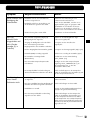
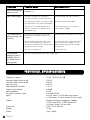
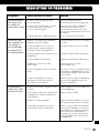
Symptom
Mögliche Fehlerursache
Abhilfe
Anzeige an der
Gerätefront
funktioniert nicht
Mit der Taste „DIMMER“ (7) ist die Anzeige
vorher abgeschaltet worden.
Betätigen Sie die Taste „DIMMER“ (7) erneut.
Schlechte
Tonqualität
Anschlüsse der Kabelverbindungen sind
lose, die Anschlüsse verschmutzt oder ein
Kabel defekt.
Prüfen Sie die Audio-Anschlüsse.
Ein Plattenspieler wurde ohne zwischengeschaltete Entzerrervorstufe (Phonovorstufe) an
einen der Hochpegel angeschlossen.
Schließen Sie eine Phonovorstufe an.
Ein Gerät mit Hochpegelausgang
(z.B. CD-Player) wurde an den Endstufeneingang „LINE5“ (11) angeschlossen.
Verwenden Sie Quellgeräte mit Hochpegelausgängen nur an den Eingängen „LINE1“
... „LINE4“.
Keine Batterien in das Handgerät eingelegt,
Batterien nicht richtig eingelegt oder
verbraucht.
Prüfen und ersetzen Sie ggf. die Batterien.
Die Sichtlinie zwischen Fernbedienung und
Gerät ist versperrt, die Reichweite wurde
überschritten oder das Handgerät wurde aus
zu weit seitlicher Position betätigt.
Versuchen Sie, die Fernbedienung nur bei
freier Sicht auf die Gerätefront, innerhalb
von 7m Entfernung und möglichst frontal
auf das Gerät zu richten.
Gerät nicht eingeschaltet.
Schalten Sie das Gerät ein.
Über die
Fernbedienung
können keine
Funktionen ausgeführt werden
Tiefton-Brummen
zu hören
Siehe Abschnitt „Netzbrummen“ im Kapitel „Weitere Tipps“.
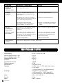
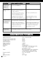
T E C H N I S C H E D AT E N
Frequenzgang:
Nennausgangsleistung an 8Ω:
Nennausgangsleistung an 4Ω:
Eingangsempfindlichkeit:
Klirrfaktor:
Signal-Rausch-Abstand:
Eingangsimpedanz:
Netzanschluss:
Eingänge:
Ausgänge:
Maße:
Gewicht:
Farbe:
22
Vincent
20 Hz - 50 kHz ±0,5 dB
200 W
289 W
400 mV
< 0.1%
>90 dB
47 kΩ
220-240V/50Hz
4x RCA stereo, 1x RCA (Main Input stereo),
1x XLR stereo
1x Power Control (3,5 mm Klinkenbuchse)
LS-Klemmen für 4 Lautsprecher,
1x PRE stereo RCA, 1x REC stereo RCA,
2x Power Control (3,5 mm Klinkenbuchse)
430 x 142 x 450 mm
23 kg
silber / schwarz
LEXIKON/WISSENSWER TES
Audio-Quellen/Audio-Quellgeräte
Komponenten Ihrer HiFi-Anlage und alle weiteren
Geräte, deren Ton Sie über das System hören möchten
und dazu an den Vor-, Vollverstärker oder Receiver
anschließen. Dazu gehören CD-Player, DVD-Player,
Tuner (Radios), Kassettenspieler, DAT-Recorder,
Personalcomputer, Schallplattenspieler, portable
Audiogeräte und viele weitere.
Dynamik
Unterschied zwischen den leisesten und dem lautesten
Tönen, die in Audio-Signalen (ohne Verzerrungen oder
Übergang in Rauschen) möglich sind.
Eingangsempfindlichkeit
Begriff für die kleinste Eingangsspannung, die bei maximaler Lautstärkeeinstellung des Verstärkers die maximale Ausgangsleistung bewirkt. Beispiele: 100 mV bis
500 mV (Millivolt) bei Hochpegeleingängen, 2 mV bis
5 mV am Phono-MM-Eingang oder 0,1 mV bis 0,5 mV
am Phono-MC-Eingang.
Pegel
Eine Art der Darstellung jeder physikalischen Größe;
gebräuchliches Maß für Signalspannungen und Lautstärke. Wird in Dezibel (dB) angegeben. Als Spannungen „auf Line-Pegel“ werden Signalspannungen unterhalb 1V bezeichnet, die als Musik-Signale für
Verstärker-Eingänge geeignet sind. Eingänge des
Verstärkers (in der Regel als Cinch-Buchse ausgeführt),
die für Signale des CD-Players, Kassettenrecorders,
DVD-Players usw. vorgesehen sind, werden auch als
„Line-Level-Eingänge“ oder „Hochpegel-Eingänge“
bezeichnet.
RCA/Cinch
RCA ist die amerikanische Bezeichnung für die koaxialen Cinch-Steckverbindungen als Abkürzung für „Radio
Corporation of America“, den Namen einer US-amerikanischen Firma. Sowohl Stecker als auch verwendete
Kabel bestehen aus einem stabförmigen Innenleiter und
einem zylinderhüllenförmigen Außenleiter. Damit lässt
sich ein Mono-Audiosignal oder ein Videosignal übertragen. Im Vergleich mit der XLR-Steckverbindung wird
diese
Verbindungsart
auch
„unsymmetrische
Signalverbindung“ („unbalanced“) genannt.
XLR
Auch: „symmetrische Verbindung“ oder „balanced“.
Eine Steckverbindung für Audiogeräte. Sie ist rund, hat
einen Durchmesser von etwa 1,5 cm und besitzt meist
drei Kontaktstifte. XLR ist eine alternative Verbindung zu
Cinch für NF-Signale im professionellen Audiobereich.
Ihr Vorteil ist die zusätzliche Übertragungsmöglichkeit
desselben Signals mit negativem Spannungshub (deswegen drei Anschluss-Stifte), so dass bei entsprechender
Signalaufbereitung im empfangenden Gerät die auf
dem Signalweg durchs Kabel eingestreuten elektromagnetischen Störungen beseitigt werden können. Des
Weiteren wird mit einem höheren Pegel übertragen.
Dadurch ist diese Art der Audiosignal-Übertragung störsicherer.
Vincent
23
SAFETY GUIDELINES
This appliance was produced under strict quality controls.
It complies with all established international safety standards.
Nonetheless, the following instructions should be fully read and
observed in order to prevent any hazard:
Do not open the appliance! Risk of electric shock!
There are no parts in the appliance that require maintenance by the user.
Maintenance/Alterations
All equipment that is connected to the domestic mains
voltage can be dangerous to the user if not handled
properly. Leave maintenance work to qualified professionals. The product is only permitted for connection
to AC 230Volt/50Hz, for earthed sockets and use in
enclosed areas. Altering the product or manipulating
its serial number voids the warranty. After a fault,
leave the appliance’s fuse to be replaced only by a
professional with one of the same kind.
Power Cable Connection
Always pull the plug and never the power cable if
you want to disconnect the appliance from the
mains power. Make sure when setting up the appliance that the power cable is not squashed, severely
bent or damaged by sharp edges. Do not touch the
power lead with wet or damp hands. Use the power
cable supplied or another one from Vincent.
ON
Switching Off
Switch the appliance off every time before you connect or remove other components or loudspeakers,
disconnect or connect it to the mains power, leave it
unused for a longer period or want to clean its outside. On all amplifiers and receivers, wait approx. 1
minute after this before disconnecting or reconnecting
the cable.
OFF
Moisture/Heat/Vibration
Contact of electrically operated equipment with
liquids, moisture, rain or water vapour is dangerous
for such equipment and the user and must be avoi24
Vincent
ded without fail. Take care that no liquids or objects
get inside the appliance (ventilation slots etc.).
It must be disconnected from the mains power immediately and examined by a professional if this happens. Never expose the appliance to high temperatures (direct sunshine) or strong vibration.
Heat Build-up
All amplifiers generate heat as part of their design.
Make sure that a gap of 5 cm remains around the
appliance and that the surrounding air can circulate (do not install in enclosed cupboards). Vents must
not be covered up.
Volume
The maximum tolerable volume is always reached well
below the maximum possible setting on the amplifier.
Be careful with the volume setting, therefore, in order
to prevent damage to hearing. So that you do not
expose yourself to high volumes unintentionally, always
set to a low level before changing the input channel.
Cleaning
Pull out the power plug before cleaning the outside
of the product. Whenever possible, use a soft, lintfree cloth that has been dampened. Do not use abrasives, solvents, thinners, flammable chemicals, polishes and other cleaning products that leave marks.
Batteries
Take note of the instructions for using batteries in
the chapter "Remote Control".
OTHER INSTRUCTIONS
Setting up the appliance
How the system is set up has an effect on the
sound quality. Therefore only place it on a suitable, stable surface. To make the most of your
system’s sound quality, we recommend placing the
equipment on Vincent racks and not putting them
on top of each other.
Old electronic equipment
This appliance is subject to the conditions set out
in the European Directive 2002/96/EC, whose
implementation is regulated in Germany by the
Electrical and Electronic Equipment Act (ElektroG).
This is identified by the symbol of a crossed out
waste bin on the appliance.
What this means for you as a consumer:
All old electrical and electronic equipment that is
no longer used must be disposed of separately
from domestic waste using places provided by the
authorities. By doing so you can prevent damage
to the environment and help to encourage manufacturers to produce more durable or reusable products. For further information about disposing
your old appliance, please consult your local authority, waste disposal agency or the shop where
you bought the product.
CE sign
This appliance complies with the current EU directives about attaining the CE mark and thus meets
the requirements for electrical and electronic
equipment (EMC regulations, regulations and regulations for low voltage equipment).
Declarations
This document was written by Andreas Böer. It is a
product of Sintron Vertriebs GmbH, 76473
Iffezheim and may not be copied or distributed partly or in full without express, written consent.
Vincent is a registered trademark of Sintron Vertriebs
GmbH, 76473 Iffezheim.
Vincent works continually to improve and develop its
products. Therefore, the appearance and technical
design of the appliance are subject to changes, as
long as they are in the interest of progress.
The content of these instructions is for information
purposes only. It can be changed at any time without
prior notice and does not constitute any obligation
on the part of the trademark’s owner. The latter assumes no responsibility or liability for errors or inaccuracies, which may be included in these operating
instructions.
Storage of the packaging
We strongly recommend that you keep the original
packaging in case you need to transport the equipment again at a later date. Transport damages are
mainly caused by improper packaging of the HiFidevices. Because the original packaging fits the
equipment accurately it will reduce the risk of
damage if transport is necessary.
Explanation of the symbols
The lightening bolt tells you that dangerous
voltages are present in the appliance, which
can cause an electric shock.
This symbol brings your attention to
particularly important information regarding
operation and maintenance.
This symbol identifies useful information and
advice about how to handle the appliance.
Vincent
25
INCLUDED IN DELIVERY
Please check the contents of the packaging, which in addition to the
appliance should contain the following accessories:
• 1 remote control VRC-1
• 2 AAA (LR3) batteries
• 1 power cable
• this manual
DESCRIPTION OF THE APPLIANCE
Despite the fact that development is constantly
moving in the direction of digital audio format
and towards audio video systems with an increasing number of channels, high quality stereo
systems still enjoy a large degree of popularity.
Some users are put off by the installation of expensive multi-channel systems and enjoy viewing DVD
films in stereo. Other music enthusiasts do not
want to switch to a surround sound system because that will never reach the sound quality of an
equally prized High-End stereo system. Those who
wish to combine both worlds - surround sound and
premium stereo -, can often not avoid having two
separate amplifiers and/or receivers, because
many multi-channel systems focus on functionality
rather than on uncompromised sound quality for
all audio channels. If that is to be avoided and the
speakers of an existing stereo system are also
required to serve as front speakers for a surround
sound system (so that a separate pair of front
speakers does not need to be acquired), then both
systems must be coupled together. For most setups
that is not possible. Only if a stereo amplifier is
used, which has the function for one of its inputs
to act only as a power amplifier, and hence provides no audio gain to this input, can the stereo
system be employed as a user friendly part of a
surround sound system.
26
Vincent
The SV-234 is the most versatile integrated stereo
amplifier from the Vincent range. It can serve both
as an amplifier for high quality stereo sources and
then, at the push of a button, it becomes a stereo
output stage (for example for the front speakers of
a home cinema system). A special feature of this
equipment is the possibility to attach a stereo source with balanced audio connectors (XLR).
Naturally, it all comes with the highest quality
workmanship and an outstanding price performance ratio.
This integrated amplifier is an ideal partner for
DVD players, CD players, tuners, headphone
amplifiers and speakers from Vincent. It can also
form part of a Vincent multi-channel system based
on a decoder preamplifier or on an AV amplifier.
In this role it supports the “Power Control” function. Together with the HiFi furniture and speaker
cables from the range, one can build a perfectly
harmonious system.
FRONT VIEW
1
2
4
1. SPEAKER A/B
If suitable speakers are used, a second pair of
speakers can be operated at the same time.
This button allows each of the speaker pairs
(designated A and B) to be individually
switched on and off. The LED located above
each of the buttons shows which of the speaker
pairs is active.
2. Display
In normal use the display shows the name of
the selected input, the volume and the operating mode (Audio Mute). When adjustments
are being made (e.g. to BALANCE, GAIN),
the relevant values are displayed.
3. LEVEL/: Volume keys
These are the keys for the adjustment of the
main volume level of the system. They consequently control the volume of the loudspeakers
and the signal of the stereo preamplifier output "PRE OUTPUT". Only for the playback of
the audio source at the input "LINE5" the
volume setting has no effect.
3
5
6
7
8
5. POWER
This is the main power switch for turning on
and off the device. Please take note of the
information about it in the sections
"Installation" and "Operating the device".
6. LED signaling display shut-off
This LED remains illuminated when the display
is switched off by the “DIMMER” (7) function.
That helps to not misinterpret a shut-off display
as consequence of a shut-off device.
7. DIMMER: Brightness setting for the
display
The brightness of the front panel display can
be reduced in two steps using this button.
If you press it repeatedly, the third actuation
switches off the display. With a fourth stroke,
the maximum display brightness will be
restored again.
8. CHANNEL: Channel Balance
These are the buttons that enable you to set
a volume difference between the left and the
right stereo channel ("BALANCE").
4. „LINE1“ … „LINE5“ and "BALANCED":
Input selection
With a touch on one of
these buttons you choose for playback the audio
source attached to the corresponding connectors at the amplifier's backside.
Vincent
27
REAR VIEW
9
10
13
12
14
9.
15
SPEAKER: Loudspeaker terminals
At these output sockets with threaded terminals
one or two pair(s) of stereo loudspeakers can
be connected. Speaker cable with 4 mm banana
plugs can be used. Please take note of the information given in the section "Installation", if two
pairs of loudspeakers will be connected to the
amplifier.
10. INPUT ("LINE1"..."LINE4"): Terminal
for stereo audio signals of the source
equipment Here you find four stereo RCA
input sockets for source equipment with analogue stereo (line level) audio output.
11. MAIN INPUT ("LINE5"): Main Amplifier
Input This is for the connection of a stereo
preamplifier or source equipment with a preamplifier output. Note that no high level output
should be connected from a stereo source to
“LINE5”. This input must also not be connected
to the neighbouring preamplifier output, “PRE
OUTPUT” (14).
12. INPUT "BALANCED": XLR-Input
These are the input sockets for one stereo
audio source equipped with XLR output sockets.
13. REC OUTPUT: Output connectors
assigned to a recording device
If desired, you can connect a recording device
28
Vincent
11
16
like a CD recorder or a tape recorder to this
output. The stereo signal of this output is identical to the output signal of the selected audio
source at one of the inputs "LINE1"..."LINE4".
The signals of the inputs "BALANCED" and
"LINE5" are not available for recording at
this output!
14. PRE OUTPUT: Preamplifier Output
If one of the inputs "LINE1"..."LINE4" (10) or the
input "BALANCED" (12) is selected, the "PRE"
output can supply two additional main amplifier
channels with the preamplified stereo audio
signal of the selected source. The output must not
be connected to the neighboring power amplifier input "LINE5 MAIN INPUT" or to the high
level input of another HiFi component.
15. POWER CONTROL (12V)
These jack connectors (3,5 mm) send and
receive the signals for the standby control
(12V Trigger).
16. AC power connector and fuse holder
To establish the power supply, connect the plugs
of the power cable to the device and to a 230V
AC wall outlet. The small plastic housing beneath
the plug opening holds the fuse. Refer to the
security precautions.
REMOTE CONTROL
Point the front of the remote control directly at
the front of the appliance, making sure there
are no objects between the remote control and
the appliance.
The distance between the remote control and the
appliance should not be more than 7 m, as the
reliability of the remote control is affected beyond
this range.
Make sure that you do not point the remote control
at an angle to the appliance, as beyond an angle
of ±30° to the centre axis the appliance may not
respond as well to the remote control. Change
both batteries if the distance at which the remote
control can be used effectively decreases.
B AT T E R I E S
Using batteries
Handling batteries incorrectly can cause battery
acid to escape or an explosion in extreme cases.
The batteries must be correctly inserted taking note
of the polarity, which is marked in the inside of the
battery compartment.
Changing/Inserting batteries:
a) Open and remove the battery compartment lid of
the remote control by tugging sharply on the fishplate on the edge of the remote control. The battery
compartment lid is held in place magnetically, there
is no need to loosen the screws!
In order to make full use of the batteries’ life, do
not mix new and used batteries. Make sure that
you insert batteries of the same type.
a
Some batteries are rechargeable, others are not
however. Take note of the precautions and instructions that are included on all batteries.
Remove the batteries if the remote control is not
going to be used for a long time.
Under no circumstances must batteries be short-circuited, taken apart or heated up.
b) If necessary, remove used batteries and insert
new ones correctly as shown by the diagram in
the battery compartment.
old
new
b
For environmental reasons, used batteries should
be disposed of in accordance with local environmental regulations and not put with domestic
waste.
c) Put the compartment cover back on and close the
battery compartment.
c
Only use AAA (LR3) size batteries.
Vincent
29
BUTTONS OF THE REMOTE CONTROL
17. MUTE
Pressing this button once mutes the sound of the
loudspeakers (9), the preamplifier output "PRE OUTPUT" (14) and the recording output "REC OUTPUT"
(13). Pressing it again returns to the original volume. The Mute function is not available if the input
"LINE5 MAIN INPUT" (11) has been selected for
playback.
17
18. Input Selector Buttons
These buttons are used to select one of the stereo
audio devices connected to the amplifier’s source
inputs for playback.
18
19. LEVEL and LEVEL : Volume keys
These buttons change the amplifier’s volume setting
for loudspeakers and the preamplifier output "PRE
OUTPUT" (14). This volume setting can not be made
if the input "LINE5 MAIN INPUT" (11) has been
selected for playback.
20. GAIN: Push button for -8dB attenuation
of Loudspeaker signals
With the activation of this function, the output signal
for the power amplifier (14) and speakers (9) is reduced by 8 dB and thus the volume of the attached
speakers. It should only be activated if even at low
volume settings the volume is already very high.
21. BAL L and BAL R
Both keys can be used for changing the volume difference between right and left speaker if that is desired. That is not possible for the source device connected to "LINE5 MAIN INPUT".
30
Vincent
20
21
19
I N S TA L L AT I O N
Set up the cable links in a sequence as follows. Connect the power cable between device and power supply only after all other connections have been made. Two loudspeakers, one ore more source devices and
the mains cable have to be connected as a minimum. The cables for power control, to recording equipment
or to another stereo amplifier must only be connected if they are to be used.
D U R I N G I N S TA L L AT I O N P L E A S E O B S E R V E
THE FOLLOWING ADVICE:
Do not connect PRE OUT and MAIN IN
No preamplifier-to-amplifier bridge circuit is required. The input "LINE5 MAIN IN" must not be connected with the neighboring preamplifier output
"PRE OUTPUT"! The preamplifier part of this amplifier is connected
internally with the
power amplifier part.
It is not possible to
split preamplifier
section and main
amplifier section to
add an effects loop (for example an equalizer).
Speaker cable connections
The use of ready-made loudspeaker cables is recommended instead of connecting the cable’s central wire (strand) directly to the terminals. Banana
plugs or cable lugs ensure high security from shortcircuits and damage to loudspeakers or amplifier.
Protective caps
Prior to the first installation the protective plastic caps must be removed
from all the connections used at the
rear of the unit.
Make sure that the positive and negative loudspeaker wires are connected correctly. You will notice a
reduced sound quality if the connections are the
wrong way round.
1
2
O UT PUTO U
RCA connections
Mechanically identical RCA plugs are available
for input and output connections. Make sure that
you do not get these connections confused during
installation!
Make sure that you do not mix up the analogue
inputs for right and left. The RCA plugs for these
are mostly colour coded as follows: red for the
right channel, black or white for the left channel.
Contacting the middle pin of the RCA plugs with
the outer ring of the RCA chassis jack may lead to
damages to the main amplifier if it is switched on!
To avoid this hazard, connect or disconnect only in
switched-off state and more than one minute after
deactivating!
Ensure that bare loudspeaker wires are never able
to come into contact with each other or with the
metal on the back of the housing. Ensure that bare
loudspeaker wires are never able to come into contact with each other or with the metal on the back
of the housing.
Only use loudspeakers with a nominal impedance
of at least 4Ω.
Cable connections
Make sure that all plugs fit tightly. Inadequate connections can cause noise interference, failures and
malfunctions.
- falsely -
- right -
To make the most of the components’ sound potential, only high quality loudspeakers and connecting
cables, for example Vincent cables, should be
used. Your local stockist will be glad to advise you
about this.
Vincent
31
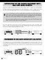
CONNECTION OF THE SOURCE EQUIPMENT WITH
RCA HIGH LEVEL OUTPUTS
Connect the outputs of these source devices with the inputs "LINE1"..."LINE4" (10) of the amplifier.
The output sockets on the source equipment are usually indicated by "Line Out", "Audio Out" or "Front
Out". You will find information about ways to connect source equipment in their operating manuals.
To use a record player you need a so-called equaliser preamplifier (also called a phono preamplifier), which is installed in the signal path between the record player and one of the high-level
inputs. Some models of record player already include this preamplifier and can be connected
directly. You will find further information in this appliance’s operating manual.
The stereo sound of appliances that use output connectors other than RCA (DIN plugs, jack
plugs) can often also be used with the aid of adaptors.
Up to four high level stereo sources can be connected to these RCA inputs. The audio inputs
"LINE1"..."LINE4" (10) represent electrically equivalent standard high level inputs with RCA connection.
They have an identical function and differ only in name.
SV-234
RCA connection
CD-Player, Tuner,
DVD-Player, etc.
LINE OUT
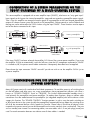
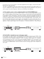
CONNECTION OF ONE AUDIO SOURCE WITH XLR OUTPUT
The "balanced" input can only be connected to a device equipped with symmetrical output. At the source device you can recognize it by the three-pin XLR-type of the output jack. Leave the XLR input of your
pre-amplifier open if none of your audio sources uses this. Sometimes both types of output connectors
are provided.
XLR connection
SV-234
e.g. CD-Player
32
Vincent
CONNECTION OF A STEREO PREAMPLIFIER OR THE
F R O N T C H A N N E L S O F A M U LT I - C H A N N E L S Y S T E M
This stereo amplifier is equipped with a main amplifier input ("LINE5"), also known as "unity gain input".
Input signals to this bypass the internal preamplifier stage and are treated as preamplifier output signals.
That is why this amplifier can accept the output signals of a preamplifier or the front channel preamplifier
outputs of a home cinema system (AV receiver or AV preamplifier). Volume control as well as Balance and
Muting can not be achieved at the SV-234 when using the input "LINE5". These functions must be operated at the device connected to this input.
SV-234
RCA connection
PRE
Stereo preamplifier
OUTPUT
SV-234
RCA connection
e.g. AV preamplifier
ANALOG
AUDIO OUTPUT
If the input "LINE5" has been selected, the amplifier SV-234 acts like a stereo power amplifier. If you want
the amplifier SV-234 to automatically switch on/off every time the HiFi component connected to "LINE5"
is switched on/off, the power control cable connections subsequently described must be applied.
Please leave the input connector "LINE5" unused if you do not wish to use the amplifier SV-234 just as
a power amplifier.
C O N N E C T I O N S F O R T H E S TA N D B Y C O N T R O L
(POWER CONTROL)
Many AV-Systems consist of a multitude of individual components. To avoid the necessity of switching them
on and off before and after every use, many manufacturers have equipped their devices with what is
known as "POWER CONTROL" circuit or "TRIGGER". This kind of remote-controlled standby circuit is
used primarily for preamplifier and power amplifiers. To employ these functions, direct or indirect cable
connections must be made between the preamplifier (or integrated amplifier) and all the devices which
support this function. The “POWER CONTROL” function operates in such a way that each switching on
or off of one device in the system (usually the preamplifier) automatically brings about the switching on or
off of all the connected devices which support this function. Please keep in mind that all devices which
respond to the power control are not disconnected from the mains network when switched off. They are
set to a standby state instead. For connecting cables, two-core cables with 3.5 mm jack plugs (mono) are
used. For each connection between two devices one of those cables is needed.
Vincent
33
If you don't wish to use this function or if the other components do not support it, all you have to do is
leave out these cable connections.
The SV-234 is equipped with one input connector and two output connectors for the power control. As a
result, this amplifier can supply and transmit the switching signal for other components in the system as
well as accept it from other components. Both cases are described in the following.
(1) The complete system is to be switched on/off at the SV-234 POWER button
In this situation the input in the terminal "POWER CONTROL" (15) must not be occupied and must be left
open. Two HiFi components that are able to react to the power control signal can be connected directly
to the amplifier's power control outputs. If more than two devices, which can be controlled, are to be connected, then it is necessary, to make the power control connection between the preamplifier and these further devices through the outputs of the two devices which are connected directly. For that reason, every
HiFi component that accepts power control signals is also equipped with a power control output. Thus, in
theory it is possible to provide an infinite number of HiFi components with the power control signal. This
approach, to loop a signal through a chain of components, is commonly referred to as "daisy chaining".
SV-234
e.g. main amplifier
(2) The SV-234 is intended to react to the trigger signal
If, for example, two output channels of a preamplifier are connected to the main input "LINE5", if this
HiFi component can supply a power control signal and if you want the amplifier SV-234 to switch on/off
synchronously with the component attached to "LINE5", one power control output of this component
must be connected to the input in the SV-234 terminal "POWER CONTROL" (15). The connector at the
sourcing HiFi component may as well be labelled with "TRIGGER OUTPUT". Both power control outputs
of the SV-234 can additionally be used to forward the received switching signal to other components of
your system.
SV-234
e.g. AV preamplifier
34
Vincent
Many devices which can be controlled by a switching signal (not preamplifiers or integrated
amplifiers), have two terminals which do not differentiate between input and output. In this case
either of the two can be selected.
"POWER CONTROL" sockets of preamplifiers or integrated amplifiers must not be interconnected! All receiving devices must not be connected to more than one preamplifier or integrated
amplifier (directly or indirectly)!
CONNECTION OF A RECORDING DEVICE
If you want, you can use the RCA sockets "REC OUTPUT" (13) on the back of the appliance to connect
an analogue stereo recording device (e.g. CD recorder, cassette recorder etc.) or another appliance that
is intended for receiving the unchanged, fixed stereo output level (line level) from the signal source selected on the amplifier at any given time. The output level is independent from the volume setting but reacts
to the "MUTE" command.
SV-234
RCA connection
e.g. Tape recorder
LINE IN
Connect this signal output to the signal input ("LINE IN", "TAPE IN" oder "REC IN") on the recording appliance using RCA cables. Please note that some recording equipment can have a slightly detrimental effect
on the audio signal quality. Some recording devices have rather low input impedance, which can slightly alter the input signal voltage. For maximal music enjoyment we recommend that you connect to the
“REC” terminal only for as long as the recording is actually being made.
CONNECTION OF TWO ADDITIONAL MAIN AMPLIFIER CHANNELS
You only need the "PRE OUTPUT" sockets (14) if you want to use a separate stereo amplifier or two mono
amplifiers to supply two additional loudspeakers. This makes sense if you intend to use two more loudspeakers for stereo music playback, for example in a separate zone (another room of your home). These
loudspeakers are then connected to the speaker outputs of the additional amplifier(s). The amplifier output connections "PRE OUTPUT" (14) must be connected with the input connectors of the main amplifier,
in most cases labelled "INPUT", "POWER AMP IN" or "MAIN INPUT".
SV-234
RCA connection
MAIN
e.g. Stereo main amplifier
INPUT
Vincent
35
CONNECTION OF THE LOUDSPEAKERS
Either a single speaker pair (A) or two speaker pairs (A+B) can be connected to the SV-234 amplifier.
Both outputs are identically provided with the stereo signal of the currently selected input source. For each
loudspeaker you will find two connector screws (positive + und negative -) at the amplifier's backside.
One side of the speaker cable must be attached here. Each pair of screws has a label "R" or "L" nearby
to clarify to which stereo channel it belongs. At the loudspeaker connection terminal there are similar connector screws or connectors. There, the polarity of each screw (+ or -) can be identified as well and the
other side of the speaker cable associated with this speaker must be attached. Make sure only connector
screws of the same polarity will be connected by each speaker cable wire: a knob marked "+" in the
amplifier's terminal must be connected with a speaker's connector screw marked "+" as well. Our sketch
shows all connections necessary for one pair of speakers. If a second pair of loudspeakers is intended to
be used, the connector screws of the lower row (Speakers B) must be connected in a similar fashion to
the additional speakers’ input connectors.
SV-234
If every speaker is connected in a conventional way (a two core speaker cable for each loudspeaker) and
you own loudspeakers that are equipped with Bi-Wiring terminals (four connector screws) you have to make
sure that the metal brackets (contact pieces consisting of small metal plates or short pieces of cable which
are supplied with the speakers) are applied to the terminal and that each one connects the two knobs of the
same polarity (e.g. both connectors marked "+"). The connector screw labelled "+" and "R" at the amplifier's backside must be connected to one of the bridged, labelled "+" connectors of the loudspeaker assigned to the right stereo channel. Accordingly, the connector screw labelled "-" and "R" at the amplifier's
backside must be connected to one of the bridged, labelled "-" connectors of the loudspeaker assigned to
the right stereo channel. Connect the left side loudspeaker in the corresponding way.
If you are using ready made loudspeaker cables with 4 mm banana plugs, all you need to do is connect
the two plugs on each loudspeaker cable end to the two associated speaker connectors. Turn the connector screws clockwise to fasten them.
36
Vincent
If you want to use speaker cables equipped with spade lug connectors, every connector screw must be
opened by turning counterclockwise. After that, the lug must be moved under the screw head. Then, turn
the screw clockwise to fasten the lug to the connector. To avoid damages to the amplifier, make sure the
connection is tight and no bare metal from the cable lug connector makes contact with the rear panel or
with another terminal.
If no connector is to be used, remove approximately 1 cm length of insulation from each end of the speaker wire. Twist the braid in order to avoid short circuits. Turn the fastener on the loudspeaker terminal counterclockwise to loosen it and introduce the bare wire end into the exposed connector hole. Then turn the
fastener clockwise so that the wire is firmly clamped. Make sure the connection is pretty tight.
If you intend to connect two pairs of speakers, all loudspeakers must have a nominal impedance
of at least 8Ω. If only one pair of speakers is used (A or B), all types of loudspeakers with a minimal nominal impedance of 4Ω can be utilised.
Consider correct polarity, the positive contact is mostly marked red or with "+". The side of the
speaker cable that has to be connected with the positive socket has a marking.
CONNECTION OF THE POWER CABLE
Check whether the wall socket provides the appropriate mains power, which is the case if it is supplied
with 230 V AC 50 Hz. Push the plug on the power cable supplied firmly into the power socket (16) on
the back of the appliance. Plug the other end of the power cable into a mains socket.
Vincent
37
O P E R AT I N G T H E A P P L I A N C E
Operation
Switch on and off
Button(s)
Description
POWER (5)
The amplifier is switched on and off using this button at the front panel.
When switched off the device is not internally separated from the AC
power and reacts to a signal at the input "POWER CONTROL INPUT"
(15). That is why it is not possible to switch off the amplifier as long as
a 12V trigger signal is present at this input.
WELCOME
As a precaution, after switching on, the volume setting should
be reduced.
Individually activate or
deactivate speaker
outputs A and B
Select an input
SPEAKER
A/B (1)
Input Selector
buttons
(10)(11)(12)
To play back stero music via loudspeakers at least one pair of them
must be attached to the amplifier (a practical choice would be
connectors "A"). The output you use must be activated using the
corresponding button "SPEAKER" (LED illuminated). Only if a second
pair of speakers is used, it is necessary to activate the second speaker
output "B".
A short touch on the button for the desired input channel
("LINE1"..."LINE5" or "BALANCED") changes to the playback of the
audio source connected there. The front panel as well as the remote
control carry those buttons. The name of the currently selected input
channel appears in the display.
LINE2
→
LINE2 -45dB
Before switching over the input channel, the volume should be turned
down as a precaution!
Change the volume
LEVEL/
(3)(19)
Hold down the button "LEVEL" to turn the volume up. Use "LEVEL" to
turn it down. This can be done on the remote control as well as at the
amplifier front panel. The display (2) shows the momentarily selected
volume value. The minimum volume value is -99dB, the maximum volume
appears at latest with 00dB, for most speakers much below this value.
LINE2 -99dB
← ... →
LINE2 00dB
The volume value can not be changed if the input "LINE5 MAIN IN"
has been selected. In this case the display shows "MAX". The volume
setting dors never influence the signal at the output "REC OUTPUT" (13).
Mute the speakers and
the preamplifier output
MUTE (17)
The MUTE function can only be operated with the remote control.
It switches off the loudspeakers, the preamplifier output "PRE OUTPUT"
(14) and the recording output "REC OUTPUT" (13). Pressing it again
restores the volume to its original setting. As long as the amplifier is
muted, the display shows "MUTING".
MUTING
38
Vincent
← ... →
MUTE OFF
O P E R AT I N G T H E A P P L I A N C E
Operation
Reduce the amplifier’s
gain (attenuation 8dB)
Button(s)
GAIN (20)
Description
Operating this key activates or deactivates an attenuation of 8dB,
which is applied to both the volume level of the speakers and also to
the signal output of the preamplifier “PRE OUTPUT” (14).
The GAIN-operation is useful, if the combination of amplifier and speaker
is so sensitive that the usable region of the volume control of the SV-234
lies at the lowest values. In this situation the volume steps are too coarse.
In this case, after first reducing the volume for the sake of caution, press
the “GAIN” button. If the GAIN setting was "00dB" (normal) before,
the display now shows "-08dB" in the front panel display. The perceived
loudness is now reduced and the output level at the preamplifier output
"PRE OUTPUT" (14) is smaller.
GAIN -08dB
← ... →
GAIN -00dB
One more keypress to "GAIN" restores the original gain setting (00dB).
The GAIN function can only be used via remote control and is not
intended to be toggled in everyday use.
DIMMER (7)
Change the brightness
of the front panel display
This function can only be operated using the associated front panel
button. When repeatedly pressed, the display brightness is reduced in
two steps (1x, 2x), switched off (3x) and restored to the original,
maximum brightness (4x).
One channel of the system (right or left) and thus one of the
loudspeakers can be adjusted to be more loud than the other one.
That may be wanted if your favorite listening position in the room is
closer to one speaker than to the other one resulting in a difference in
perceived volume. This balance adjustment can be made using the
corresponding remote controller buttons as well as using the
front panel buttons.
BAL L/R
(21)
Change the channel
balance
CHANNEL
(8)
LEVEL/
(3)(19)
You are free to change the setting in 10 steps to each side (right or left).
The maximum difference appears at the setting displaying "+10dB".
The BALANCE setting does not affect the recording output (13) and is
not active as long as the input "LINE5 MAIN INPUT" (11) is selected.
Using the remote control: Press, if necessary repeatedly, the button
"BAL L" to boost the left channel volume compared to the right channel
volume. "BAL R" can be used to boost the right channel volume.
At the front panel: Press the button "CHANNEL" and don’t wait too long:
use "LEVEL" or "LEVEL" to change the BALANCE setting. While doing
this, the display shows the current BALANCE value and the side
(R: right or L: left) to which the BALANCE has been moved.
BAL L +10dB
← ... →
BAL 00dB
← ... →
BAL R +10dB
Vincent
39
TIPS
Burn in/ Warm up
Your audio components need a certain time
period until they reach maximum performance.
The duration of this "warm up" time is very different for the various elements of your audio system.
Higher and homogeneous sound quality is achieved while keeping the device switched on.
speakers, subwoofers, record players or headphone amplifiers that are connected to the audio
inputs of the amplifier. Another possible reason for
humming noise is electromagnetic interference of
other components’ power supplies with pick-upsystems of record players (change the place of the
record player for a test).
Your audio specialist dealer has enough experience to give you more information.
In most electric devices the ground potentials of all
signals are connected to each other at one central
point, where they have one common connection.
If the device uses the protective conductor of the
wall outlet, the corresponding wire of the line cord
is connected intractably to the metal housing of
the device. This is the mostly the point where the
central grounding point is attached to. By doing
this the housing is able to shield all signals from
external radiated noise. Some main amplifiers are
equipped with a "Ground Lift"-switch. If it is activated, ground potential of the chassis and the protective ground wire are being separated from the
central signal ground point. The protective ground
wire keeps its function. Sometimes this helps prevent noise caused by errors in grounding.
Net frequency noise
Some audio source devices may in combination
with the amplifier cause a humming noise at
power line frequency audible from your speakers.
Usually, its volume varies with the volume setting
of the amplifier. This is no sign of a defect or fault
of your audio products but has to be eliminated.
Generally, every wall-powered device connected
to the ground wire of the power plug can cause
this problem when connected to the amplifier.
Experience shows that this problem is mainly caused by antenna-connected components (as TV-sets
or Tuners), personal computers, electrostatic loud-
40
Vincent
If the problem occurs and cannot be solved by
yourself your audio specialist dealer will help you.
SEARCH FOR ERRORS
Symptom
Possible Cause
Countermeasure
Unit does not work
after pressing the
power button
Mains cable is not connected to a suitable
mains wall outlet.
Connect to a functioning socket using a
suitable mains voltage.
Mains cable has not been firmly inserted into
wall power socket and the device’s socket.
Otherwise it may be defective.
Check the power cable. If necessary,
exchange it with a suitable mains cable
and push its plug firmly into wall socket and
the device's power connector.
Unit fuse or unit is defective.
Contact your dealer.
The currently selected audio source
(10)(11)(12) is giving no signal.
Switch on the source unit and begin playback.
The output of the source device is not connected or is wrongly connected e.g. not connected
to the selected input channel terminal of
the amplifier.
Correct the connection.
Wrong input channel has been selected at
the amplifier.
Set the amplifier to the input that your
desired source is connected to (10)(11)(12).
Volume (LEVEL) is set too low.
Carefully increase the volume (3)(19).
The amplifier is muted (MUTE-Function).
Deactivate the MUTE function (17) after, as
a precaution, reducing the volume level.
The output of the speaker pair you want to
use has not been activated.
After, as a precaution, reducing the volume
level, press the "SPEAKER A/B" button (1)
associated to the speaker output used, so that
the LED next to the key is illuminated.
The speaker cable is not properly connected
to the amplifier's terminal. Otherwise it may
be defective.
Check and tighten the speaker cables at the
amplifier and the speakers.
The source equipment is giving signal on
only one channel.
Check the audio source. You can try to use it
at a different amplifier for a test.
One of the signal cables between audio source
and amplifier inputs has not yet been plugged
in or is defective.
Check the cable connections, tighten them
if necessary.
Channel balance has been set to the extreme
right or left.
Set the channel balance to a reasonable value.
One of the speaker cables is not correctly
connected or is defective.
Check and refasten the speaker cables at the
speaker terminal of the amplifier and at the
speaker’s connectors. The cables coming
from both the speakers of a speaker pair must
not be connected to different terminal sets (e.g.
one A and one B) on the back of the amplifier.
No sound on both
channels although
the unit is ready for
use (front panel
display is functional)
No audio playback
on one channel
Vincent
41
Symptom
Possible Cause
Counter measur e
Front panel display
does not work
It has been switched off before using
"DIMMER" (7).
Press the button "DIMMER" (7) one more time.
Poor sound quality
The cable connections are not tight, the
connectors are dirty or a cable is defective.
Check the cables and cable connections.
A record player has been connected to a high
level input without using a phono preamplifier.
Interconnect a phono preamplifier.
An audio source with standard line level
output is connected to the amplifier direct
input "LINE5" (11).
Use line level audio sources only at the
inputs "LINE1"..."LINE4".
No batteries inserted in the remote control,
batteries are not inserted correctly or are
depleted.
Check and replace the batteries if necessary.
The line-of-sight between the remote control
and the unit is obstructed, the range was
exceeded or the hand unit was operated from
a position too far to one side.
Try to point the remote control at the front of
the unit only when the sight-line is clear,
within a 7-metre distance and, if possible,
facing the unit.
The unit is not switched on.
Switch on the unit.
The remote control
cannot perform any
functions
Humming low
frequency noise is
audible, even as
no audio source is
playing back
See section "Net frequency noise" in the chapter "Tips".
T E C H N I C A L S P E C I F I C AT I O N S
Frequency response:
Nominal Output Power at 8Ω:
Nominal Output Power at 4Ω:
Input sensitivity:
Total Harmonic Distortion:
Signal to Noise Ratio:
Input Impedance:
AC power connection type:
Inputs:
Outputs:
Dimensions:
Weight:
Colour:
42
Vincent
20 Hz - 20 kHz ±0,5 dB
200 W
289 W
400 mV
< 0.1%
>90 dB
47 kΩ
220-240V/50Hz
4x RCA stereo, 1x RCA Main Input stereo,
1x XLR stereo, 1x Power Control (3,5 mm jack)
Speaker connectors accepting 4 speakers,
1x PRE stereo RCA, 1x REC stereo RCA,
2x Power Control (3,5 mm jack)
430 x 142 x 450 mm
20 kg
silver / black
GLOSSARY
Audio Sources/Source devices
These are the components of your HiFi system and
all other appliances, whose sound you want to hear
over the system and are thus connected to the preamplifier, amplifier or receiver. This includes CD
players, DVD players, tuners (radios), cassette players, DAT recorders, personal computers, record
players, portable audio devices and many more.
Input sensitivity
Term for the smallest average (RMS) input voltage
which causes the maximum output power at the
maximum volume setting on the amplifier.
Examples: 100 mV to 500 mV (Millivolts) on high
level inputs, 2 mV to 5 mV on the phono MM input
or 0.1 mV to 0.5 mV on the phono MC input.
dB-Level
This is a way of describing any physical quantity; it
is a common measurement for signal voltages and
the volume. It is given in decibels (dB). Alternating
signal voltages below 1V (RMS) are described as
"line level" voltages, which are suitable as music
signals for amplifier inputs. Inputs on amplifiers
(mostly represented by RCA sockets), which are
designed for signals on the CD player, tape recorder, DVD player etc. are also referred to as "line
level inputs" or "high-level inputs". Those signal
inputs must not be confused with inputs that accept
preamplified signals.
RCA
RCA is the American name for coaxial RCA connectors and sockets, originally the abbreviation for
"Radio Corporation of America", the name of a
United States company. Both the plug and cable
consist of a rod-shaped inner lead and a cylindrical-shaped outer lead. This enables a mono audio
signal or a video signal to be transmitted.
Compared to the XLR plug connector, this type of
connection is also called "unbalanced signal connection".
XLR
Also: "Symmetrical Connection" or "balanced".
A plug-and-socket connection for audio devices.
It is round (with approx. 1.5 cm in diameter) and
has 3 contacts/pins. XLR is an alternative connection to RCA used to transmit NF-Signals in professional audio equipment. The advantage is one additional transmission path for the same but phase inverted signal. If the receiving device can process this,
all inducted noise received in the cable screen can
be eliminated. The signal voltage level used for this
type of transfer is higher, so it is a more robust less
sensitive signal path.
Vincent
43
CONSIGNES DE SECURITE
La construction de cet appareil a été soumise à des contrôles de
qualité très stricts. Il répond à toutes les normes internationales de
sécurité. Il est cependant nécessaire de lire entièrement les
consignes suivantes et de les appliquer pour éviter tout danger :
Ne pas ouvrir l'appareil! Danger de décharge électrique!
Aucune pièce à entretenir par l'utilisateur ne se trouve dans l'appareil.
Entretien/Modifications
Tous les moyens d'exploitation raccordés
au secteur du foyer peuvent représenter un danger
pour l'utilisateur en cas d'usage non conforme. Faites
toujours effectuer l'entretien par un personnel qualifié.
Ce produit n'est autorisé que pour être branché que
sur un courant alternatif de 230Volt/50Hz, les prises
de courant de sécurité et destiné à être employé dans
des pièces fermées. La présente garantie ne s'applique si le produit a été modifié par l'acheteur ou le
numéro de série du produit a été modifié ou supprimé. Après une défaillance, faites remplacer le dispositif de sécurité de l'appareil uniquement par un exemplaire de même type et par un spécialiste.
Câble d'alimentation/Branchement
Lorsque vous débranchez l'appareil du secteur, retirez-le en le tenant par la prise, mais jamais en tirant
sur le câble. Lors du montage de l'appareil, assurez-vous que le câble n'est pas écrasé, plié à l'extrême ou endommagé par des arêtes tranchantes.
Ne saisissez pas l'appareil avec les mains mouillés
ou humides. Utilisez le câble fourni ou un autre
câble de Vincent.
ON
Développement de chaleur
Tous les amplificateurs génèrent de la
chaleur de par leur construction. Veillez à respecter
une distance de 5 cm pour que l'air ambiant puisse
circuler (ne pas monter l'appareil dans un placard
fermé). Les orifices d'aération ne doivent pas être
couverts.
Puissance sonore
La puissance sonore maxi supportable est
atteinte largement en-deçà du réglage possible de
l'amplificateur. Agissez avec prudence avec le réglage
du son pour ne pas vous exposer à des dommages
auditifs. Réglez le son sur une valeur moindre avant de
changer de canal d'entrée pour ne pas être exposé
sans le vouloir à une plus forte puissance sonore.
Arrêt
Arrêtez chaque fois l'appareil avant de
raccorder ou de retirer d'autres composants ou les
haut-parleurs, de le débrancher du secteur ou de le
raccorder au secteur, si vous ne l'utilisez pas pendant
une longue période ou si vous voulez nettoyer sa surface. Attendez environ une minute avant de brancher
ou de débrancher les jonctions de câble des amplificateurs, des niveaux maxi et des récepteurs.
Nettoyage
Débranchez le connecteur avant de
nettoyer les surfaces extérieures du produit.
Utilisez de préférence un chiffon doux, non pelucheux et humide. Evitez les produits abrasifs, les
solvants, les diluants, les produits chimiques, les
produits à polir et tous les autres nettoyants qui
laissent des traces.
Humidité/Chaleur/Vibrations
Le contact d'appareils électriques
avec des liquides, l'humidité, la pluie ou la vapeur
Piles
Observez les consignes d'utilisation des
piles fournies au chapitre « Télécommande ».
OFF
44
d'eau représente un risque pour les appareils et
leurs utilisateurs et doit donc être absolument évité.
Faites attention à ce qu'aucun liquide ou objet ne
pénètre dans l'appareil (fentes d'aération etc.). Si
cela a été le cas, il doit immédiatement être débranché du secteur et contrôlé par un spécialiste.
N'exposez jamais l'appareil à des températures
élevées (insolation) ou à de fortes vibrations.
Vincent
AUTRES CONSIGNES
Montage de l'appareil
Le site de montage de l'appareil a une
incidence sur le son. Posez l'appareil uniquement
sur une surface appropriée et stable. Pour profiter
pleinement du potentiel sonore de votre système,
nous vous recommandons de placer les appareils
sur des racks Vincent et de ne pas les poser l'un
sur l'autre.
Appareils électroniques usagés
Cet appareil est soumis aux dispositions
fixées dans la directive européenne 2002/96/
CE, dont la l'application est dictée en Allemagne
par la Loi sur les appareils électriques et électroniques (ElektroG). L'identification est fournie sur l'appareil par le symbole représentant une poubelle rayée.
Pour le consommateur, cela signifie :
Tous les appareils électriques ou électroniques qui
ne sont plus utilisés ne doivent pas être éliminés
avec les déchets ménagers, mais dans les déchetteries prévues. Vous éviterez ainsi de polluer l'environnement et contribuerez à motiver les fabricants dans la production d'appareils à longue
durée de vie ou réutilisables. Pour toute information complémentaire sur la mise au rebut de l'ancien appareil, veuillez vous adresser à votre mairie, au service de déchetterie ou au magasin où
vous l'avez acheté.
Sigle CE
L'appareil répond aux directives UE pour
l'obtention du sigle CE et par conséquent aux exigences concernant les appareils et électroniques
(directives CEM, directives de sécurité et directives
des appareils à basse tension).
Explications/Remarques
Le présent document a été rédigé par
Andreas Böer. Il s'agit d'un article de la société
Sintron Vertriebs GmbH, 76473 Iffezheim qui ne
doit être ni copié, ni distribué dans sa totalité ou en
partie sans accord explicite et écrit.
Vincent est une marque enregistrée de la société
Sintron Vertriebs GmbH, 76473 Iffezheim.
Vincent travaille en permanence à l'amélioration et
au développement de ses produits. Pour cette raison, des modifications de design et de construction
technique liées au progrès sont possibles.
Le contenu de ces instructions a uniquement un
caractère d'information. Il peut être modifié à tout
moment sans information préalable et n'a pas valeur
d'obligation pour le propriétaire de la marque. Ce
dernier n'assume aucune responsabilité pour les
erreurs ou les imprécisions pouvant y être contenues.
Conservation de l’emballage
Nous vous recommandons vivement de ne pas
jeter l’emballage d’origine de l’appareil afin de
pouvoir le réutiliser pour un éventuel autre transport. Des dommages de transport se produisent
fréquemment sur des appareils Hi-Fi lorsqu’ils sont
emballés dans des emballages non adaptés.
Comme l’emballage d’origine est parfaitement
adapté à l’appareil, le risque de détérioration pendant le transport est fortement réduit.
Explication des symboles graphiques
L'éclair indique que l'appareil peut générer
des tensions dangereuses pouvant provoquer
une décharge électrique.
Ce symbole a pour but d'attirer l'attention
sur les consignes particulièrement importantes concernant la commande et l'entretien.
Ce symbole caractérise des informations et
des consignes utiles concernant la manipulation de l'appareil.
Vincent
45
OBJET DE LA LIVRAISON
Veuillez contrôler le contenu de l'emballage. Les accessoires suivants
doivent être joints à l'appareil :
• 1 télécommande VRC-1
• 2 piles de type AAA (LR3)
• 1 câble de distribution
• le présent manuel
D E S C R I P T I O N D E L ' A P PA R E I L
Bien que le développement aille constamment
dans le sens de formats de son numérique et de
systèmes audio-vidéo multicanaux, les installations
stéréo de qualité supérieure continuent d’être très
appréciées. Beaucoup reculent devant l’installation de systèmes multicanaux onéreux et préfèrent
apprécier les films DVD en stéréo. Certains audiophiles ne souhaitent pas passer aux systèmes
ambiophoniques, parce que les sources High-EndStereo ne peuvent pas déployer tout leur potentiel
sonore avec certains systèmes surround. Celui qui
souhaite concilier les deux mondes - Surround et
Premium-Stereo -, ne pourra généralement pas éviter de s’équiper de deux amplificateurs ou récepteurs séparés, car de nombreux systèmes multicanaux misent plutôt sur la fonctionnalité que sur la
qualité sans compromis du son de tous les canaux
sonores. Si les haut-parleurs stéréo existants, le
plus souvent de qualité supérieure, doivent aussi
servir de haut-parleurs frontaux (pour éviter une
paire supplémentaire de haut-parleurs frontaux),
les deux installations devront être couplées. Dans
de nombreux cas, ceci ne sera pas possible.
Seulement si on dispose d’un amplificateur stéréo,
en utilisant une des ses entrées uniquement
comme amplificateur de puissance et sans réglage de volume pour cette entrée, ce système stéréo
peut être utilisé de façon satisfaisante comme partie de l’installation surround.
46
Vincent
L’appareil SV-234 est l’amplificateur stéréo le plus
polyvalent du programme Vincent. Il peut en
même temps, servir d’amplificateur aux sources
stéréo de qualité supérieure et par un simple
appui sur un bouton, devenir un ampli stéréo de
puissance (par exemple pour les haut-parleurs
frontaux d’un système de home cinéma). Une de
ses particularités est la possibilité de raccordement d’une source stéréo avec des sorties symétriques (XLR). Bien entendu, la qualité de finition la
plus élevée et un excellent rapport prix performance vont de soi.
Cet amplificateur est un partenaire idéal pour lecteurs de DVD, lecteurs de CD, de tuners, d’amplificateurs de casque d’écoute et de haut-parleurs
de Vincent. Il peut aussi être intégré dans une
installation multicanal de Vincent, basée sur un
préamplificateur ou un amplificateur de décodeur
ou un amplificateur AV. Dans ce but, il supporte la
fonction de commande de mise sous tension
("Power Control"). Adapté aux meubles HiFi et
aux câbles de haut-parleurs du programme, on
peut construire un système parfaitement harmonieux.
FA C A D E AVA N T
1
2
4
1. SPEAKER A/B : touches de commutation
ou de coupure des deux paires de
haut-parleurs
Avec des haut-parleurs appropriés, on peut
aussi utiliser simultanément une deuxième
paire de haut-parleurs. Avec ces touches, on
peut commuter ou couper séparément chacune
des deux paires de haut-parleurs (désignées
par A et B). Chacune des LED située au-dessus
de la touche, indique la paire de haut-parleurs
activée.
2. Affichage
En mode normal, affiche le nom du canal
d’entrée sélectionné, le réglage du volume et
l’état de fonctionnement (sourdine). Les valeurs
correspondantes sont affichées, pendant que
l’on procède aux réglages (BALANCE, GAIN).
3. LEVEL/: touches de volume
Ces touches servent au réglage du volume
total du système, c’est-à-dire le volume des
haut-parleurs et le signal de sortie du préampli
stéréo "PRE OUTPUT". Seulement pour l’en trée
"LINE5", le réglage de volume est sans effet.
3
5
6
7
8
4. „LINE1“ … „LINE5“ et "BALANCED":
touches de sélection d’entrées
Servent à sélectionner les différentes sources
d’entrées raccordées à l’amplificateur
(10)(11)(12).
5. POWER: commutateur secteur
Sert à mettre l’appareil en MARCHE ou à
l’ARRET. Respectez les instructions de la commande de mise sous tension (POWER CONTROL) des paragraphes "Installation" et
"Utilisation de l’appareil".
6. LED pour la coupure de l’affichage
S’allume, pendant que l’affichage est éteint
par la fonction "DIMMER" (7), afin que cet
état ne soit pas confondu avec l’état ARRET
de l’appareil.
7. DIMMER: luminosité de l’affichage
Sert à réduire la luminosité de l’affichage (2)
à deux niveaux ou à l’éteindre.
8. CHANNEL: balance du volume
Sert à régler la "BALANCE" (différence de
volume entre les canaux gauche/droit) en
utilisant les touches "LEVEL" (3)(19).
Vincent
47
FA C A D E A R R I E R E
9
10
13
12
14
9.
15
SPEAKER : bornes de raccordement
des haut-parleurs Douilles de sortie avec
serrage à vis pour le raccordement d’une ou de
deux paires de haut-parleurs. On peut utiliser
des câbles de haut-parleurs avec fiches banane
de 4 mm. Respectez les instructions du chapitre
"Installation" dans le cas où deux paires de
haut-parleurs doivent être raccordées.
10. INPUT ("LINE 1" ... "LINE 4") :
raccordement d’appareils source
stéréo avec sortie de haut niveau
Quatre bornes d’entrée stéréo RCA pour
appareils source avec sortie son stéréo
analogique de haut niveau.
11. MAIN INPUT ("LINE 5") : entrée ampli
de puissance Raccordement d’un préamplificateur stéréo ou d’un appareil source avec
sortie préamplificateur. Veuillez noter qu’aucune sortie de haut niveau d’une source stéréo ne
doit être raccordée sur "LINE 5". L’entrée ne
doit pas non plus être raccordée à la sortie
voisine du préamplificateur "PRE OUTPUT" (14).
12. INPUT "BALANCED" : entrée XLR
Borne d’entrée pour un appareil source stéréo
avec borne de raccordement symétrique (XLR).
48
Vincent
11
16
13. REC OUTPUT : sortie pour
enregistrement Sert à raccorder, si souhaité,
par exemple un appareil d’enregistrement.
Le signal stéréo de cette sortie, est identique à
celui du signal de sortie de la source actuellement
sélectionnée à l’une des bornes "LINE 1"..."LINE 4".
Les signaux des appareils raccordés à "LINE 5"
et "BALANCED" ne sont pas amenés jusqu’à la
sortie pour enregistrement.
14. PRE OUTPUT : sortie de préamplificateur Si une des entrées "LINE 1" ... "LINE 4"
(10) ou l’entrée "BALANCED" (12) est sélectionnée, cette sortie peut transmettre le signal son
stéréo préamplifié de la source actuellement
sélectionée à deux canaux de puissance supplémentaires ou à un Subwoofer actif. La sortie ne
doit pas être raccordée à l’entrée de puissance
voisine "LINE 5 MAIN INPUT" (11) ou à l’entrée
de haut niveau d’un autre appareil.
15. POWER CONTROL (12V)
Les signaux de commande de mise sous tension
(Trigger) sont reçus et envoyés via ces douilles
jack (3,5 mm).
16. Prise secteur avec porte-fusible
Raccordez ici le cordon secteur et branchez-le au
secteur. Le petit boîtier en plastique en dessous de
la prise secteur contient le fusible de l’appareil.
Respectez les consignes de sécurité à ce sujet.
TELECOMMANDE
Orientez la partie avant de la télécommande
directement vers la face de l'appareil. Aucun
obstacle ne doit se trouver entre la télécommande
et l'appareil. La distance entre la télécommande
et l'appareil ne doit pas être supérieure à 7m, car
la fiabilité de la télécommande diminue au-delà
de cette portée.
Veillez à ne pas orienter obliquement la télécommande vers l'appareil, car au-delà d'un angle de
±30° par rapport à l'axe central, l'appareil peut
éventuellement réagir moins bien aux instructions
de commande. Remplacez les deux piles lorsque
la distance d'utilisation de la télécommande par
rapport à l'appareil diminue.
PILES
Utilisation des piles
L'utilisation non conforme des piles peut causer
une fuite d'acide et, dans des cas extrêmes, une
explosion.
Les piles doivent être insérées correctement quant
à leur polarité, comme cela est indiqué par les
repères présents à l'intérieur du boîtier des piles.
Remplacement/Insertion des piles
a) Ouvrez et enlevez le couvercle du logement des
piles de la télécommande, en soulevant fortement
la languette située au bord de la télécommande.
Le couvercle du logement à piles est maintenu par
un aimant, ne pas desserrer les vis !
a
N'utilisez pas des piles neuves et usagées en
même temps pour utiliser la durée de vie entière
des piles. Faites attention à utiliser des piles de
même type.
Certaines piles sont rechargeables, d'autres ne le
sont pas. Observez les consignes de précaution et
les instructions fournies sur les piles.
Retirez les piles si vous n'utilisez pas la télécommande pour une durée prolongée.
b) Retirez éventuellement les piles usagées et insérez correctement les piles neuves comme indiqué
sur le schéma dans le compartiment des piles.
vieux
b
nouveau
Les piles ne doivent en aucun cas être court-circuitées, démontées ou chauffées.
Eliminez les piles usagées conformément aux dispositions locales de protection de l'environnement
et ne les jetez pas avec les ordures ménagères.
c) Remettez le couvercle du compartiment et fermez
le compartiment
des piles.
c
Utilisez exclusivement des
piles rondes AAA (LR3).
Vincent
49
TOUCHES DE LA TÉLÉCOMMANDE
17. MUTE : touche de mise en sourdine
Coupe les signaux de sortie des bornes de
serrage de haut-parleurs (9), de la sortie du
préamplificateur "PRE OUTPUT" (14) et de la
sortie pour enregistrement "REC OUTPUT" (13).
La mise en sourdine ne peut pas être activée
quand l’entrée "LINE 5 MAIN INPUT" (11)
est sélectionnée.
18. Touches de sélection d’entrées
Servent à la sélection de l’appareil source
raccordé, dont on veut écouter la reproduction.
19. LEVEL et LEVEL : touches de volume
Servent à modifier le réglage du volume de
l’amplificateur des haut-parleurs (9) et de la
sortie du préamplificateur (PRE OUTPUT (14)).
Le réglage n’a pas d’influence sur le volume,
quand l’entrée "LINE 5 MAIN INPUT" est sélectionnée.
20. GAIN : atténuation -8dB des signaux
des sorties de haut-parleurs et de la
sortie du préamplificateur
Après activation de cette fonction, les signaux
de sortie de l’amplificateur de puissance et des
haut-parleurs sont atténués de "-08dB" et le
niveau des haut-parleurs raccordés abaissé.
Ne devrait être activé, que si pour des valeurs
basses de volume, le volume est déjà très élevé.
21. BAL L et BAL R : touches pour différences de niveau de volume entre
canal gauche/droit
Si vous le souhaitez, vous pouvez régler la
différence de niveau du volume entre le canal
gauche et le canal droit. Ceci n’est pas possible, pour la source raccordée à l’entrée "LINE5
MAIN INPUT".
50
Vincent
17
20
21
18
19
I N S TA L L AT I O N
Réalisez les raccordements de câbles dans l’ordre préconisé ci-dessous. Raccordez d’abord le cordon secteur à l’appareil, puis branchez-le à la prise du secteur. Il faut dans tous les cas, raccorder deux haut-parleurs, un ou plusieurs appareils source ainsi que le cordon secteur. Les câbles pour la commande de mise
sous tension, de l’appareil d’enregistrement ou pour une autre amplification de puissance stéréo ne doivent
être raccordés que s’ils sont nécessaires.
VEUILLEZ TENIR COMPTE DES INSTRUCTIONS
S U I VA N T E S L O R S D E L’ I N S TA L L AT I O N :
Pas de nécessité de liaison préampli,
ampli de puissance
L’entrée "LINE 5 MAIN IN" (11) ne doit pas être raccordée avec la sortie voisine de préamplification
"PRE OUTPUT" (14). Le préamplificateur est relié de
façon interne avec
l’amplificateur de
puissance. Il n’est pas
possible, en utilisant
ces prises, de relier
un appareil entre
préamplificateur et
amplificateur de puissance intégrés
(circuit à effets, boucle à effets)!
1
2
Dépose du capot de protection
Avant la première installation, retirez
O UT PUTO U
les capuchons de protection des
connecteurs à utiliser, situés sur la façade arrière
de l’appareil.
Prises RCA
Des branchements RCA mécaniquement identiques
existent en tant que connexions des entrées et des
sorties. Veillez à ne pas mélanger ces connexions
lors de l'installation!
Veillez à ne pas intervertir les entrées analogiques
droite et gauche. Souvent, de telles connexions
RCA présentent les couleurs suivantes : rouge pour
le canal de droite, noir ou blanc pour le canal de
gauche.
Un contact entre la broche centrale de la fiche
RCA avec la douille extérieure de contact de la
fiche RCA, peut dans le pire des cas, provoquer
une détérioration des appareils, lorsque ceux-ci
sont sous tension. C’est pourquoi, il ne faut jamais
changer les raccordements lorsque les appareils
sont sous tension !
Fiches de raccordements
Veillez à ce que les jonctions soient bien fixées. Les
connexions insuffisantes peuvent causer des parasites, des défaillances et des dysfonctionnements.
- Faux -
- Correctement -
Prise de haut-parleur
Nous vous recommandons d'utiliser des câbles de
haut-parleurs confectionnés, au lieu de connecter
directement le conducteur intérieur (toron) du câble.
Les fiches banane ou les cosses de câble offrent une
plus grande sécurité contre les courts-circuits ou l'endommagement des haut-parleurs ou de l´amplificateur.
Assurez-vous que les fils des haut-parleurs dénudés
ne puissent entrer en contact entre eux ou toucher le
métal du dos de l'appareil!
Veillez au branchement correct des fils de haut-parleurs positif et négatif. Un branchement interverti se
fait remarquer par une baisse de qualité du son.
Utilisez uniquement des haut-parleurs d'une impédance minimale de 4Ω.
Câbles de liaison
Pour exploiter au mieux le potentiel de qualité
sonore des composants, on ne devrait utiliser que
des câbles de liaison et de haut-parleurs de qualité supérieure, par exemple des câbles Vincent.
Utilisez de préférence des câbles audio blindés.
Votre revendeur se fera un plaisir de vous conseiller à ce sujet.
Vincent
51
R A C C O R D E M E N T D E S A P PA R E I L S S O U R C E AV E C
LA SOR TIE HAUT NIVEAU RCA
Raccordez les sorties de ces appareils source avec les entrées "LINE 1" ... "LINE 4" (10) de l’amplificateur. La plupart des bornes de sortie sont désignées par "LINE OUT", "AUDIO OUT" ou "FRONT OUT".
Vous trouverez des informations sur les possibilités de raccordement des appareils source dans leur mode
d’emploi.
Pour utiliser une platine tourne disque, il vous faut utiliser un préamplificateur phono soi-disant
correcteur préliminaire, qui est installé dans le réseau des signaux entre la platine tourne disque et l'une des entrées du niveau supérieur. Certains modèles d'platine tourne disque en sont
déjà équipés et peuvent donc être directement branchés. Vous trouverez des informations complémentaires dans les instructions de service de cet appareil.
Souvent, avec l’aide d’adaptateurs, on pourra utiliser le son stéréo d’appareils, dont les sorties
ne peuvent pas être raccordées avec des douilles de sortie RCA, mais d’autres fiches (fiche DIN,
fiche à Jack).
Il est possible de raccorder jusqu’à quatre sources stéréo avec les sorties haut niveau RCA. En ce qui concerne les entrées son correspondantes "LINE 1" ... "LINE 4" il s’agit d’entrées haut niveau de qualité électrique standard identique avec prise RCA. Elles ont une fonction identique, elles ne se distinguent que par
leur désignation.
SV-234
connexion RCA
par ex. lecteur CD
LINE OUT
RACCORDEMENT D’UN APPAREIL SOURCE
AVEC LA SOR TIE STEREO-XLR
L’entrée "BALANCED" () ne peut être raccordée qu’avec un appareil, qui possède aussi une telle sortie
symétrique. Vous la reconnaîtrez à la forme des prises nommées XLR. Laissez cette entrée libre, si aucune de vos sources audio n’utilise ce type de connexion. Parfois des appareils source audio possèdent
aussi les deux types de raccordement.
connexion XLR
SV-234
par ex. lecteur CD
52
Vincent
RACCORDEMENT D’UN PREAMPLIFICATEUR STEREO OU
DES CANAUX FRONTAUX D’UN SYSTEME MULTICANAL
Cet amplificateur intégré est équipé d’une entrée ("LINE 5"), dont le signal contourne le préamplificateur
(appelée entrée "unity gain"). Ceci permet de relier celui-ci avec la sortie de préamplificateur d’un autre
appareil ou les sorties de préamplificateur pour les canaux frontaux d’un système de home cinéma (récepteur AV ou préampli AV). Le préamplificateur raccordé prend alors en charge le réglage du volume ainsi
que la fonction BALANCE et la mise en sourdine (MUTE).
SV-234
connexion RCA
PRE
amplificateur stéréo
OUTPUT
SV-234
connexion RCA
par ex. préamplificateur AV
ANALOG
AUDIO OUTPUT
Si l’entrée "LINE 5" est sélectionnée, l’amplificateur SV-234 se comporte comme un étage de sortie stéréo.
Si l’amplificateur SV-234 utilisé comme étage de sortie, doit être automatiquement mis à l’arrêt en même
temps que le préamplificateur, les liaisons par câbles décrites ci-dessous doivent être effectuées correctement
pour la commande de mise sous tension.
Laissez l’entrée "LINE 5" libre, si vous ne voulez pas utiliser l’amplificateur SV-234 comme étage de sortie.
LIAISONS CABLEES POUR LA COMMANDE DE MISE
SOUS TENSION (POWER CONTROL)
De nombreux systèmes AV se composent de nombreux composants individuels. Pour éviter de les mettre
en marche et de les arrêter l’un après l’autre à chaque utilisation, certains fabricants ont équipé les appareils avec un circuit appelé "TRIGGER", ou aussi "Power Control" ou encore "Commande de mise sous
tension". Ce type de télécommande Standby est avant tout utilisé pour les préamplificateurs et les amplificateurs. Pour pouvoir l’utiliser, des liaisons câblées doivent être réalisées directement ou indirectement
entre le préamplificateur et tous les appareils qui supportent cette fonction. La fonction "POWER CONTROL" a pour effet, de mettre en marche ou d’arrêter automatiquement tous les appareils, qui supportent
cette fonction, en même temps que la mise en marche ou l’arrêt d’un des appareils raccordés au système
(en général le préamplificateur). Veuillez noter que tous les appareils qui réagissent à la commande de
mise sous tension, ne sont pas coupés du secteur, mais seulement maintenus en état de veille. On utilise
pour cela des câbles à deux conducteurs, équipés de fiches banane 3,5 mm (mono). Pour chaque liaison
entre deux appareils, il faut utiliser un de ces câbles.
Vincent
53
Si le mode de fonctionnement décrit ci-dessus n’est pas souhaité, il suffit, la plupart du temps, de renoncer aux liaisons câblées décrites dans ce paragraphe.
L’appareil SV-234 possède une prise d’entrée et deux prises de sortie pour la commande de mise sous
tension. Il peut ainsi, aussi bien générer et émettre le signal de mise sous tension pour d’autres composants d’une installation stéréo, que réagir au signal de mise sous tension d’un autre appareil. Les deux
cas sont décrits dans ce qui suit.
(1) L’ensemble du système doit être mis en marche et arrêté à partir de l’amplificateur SV-234
Dans ce cas, l’entrée du "POWER CONTROL"(15) doit rester libre. Deux appareils qui doivent recevoir
le signal de mise sous tension, peuvent être directement raccordés aux deux sorties du "POWER CONTROL" (15). S’il y a plus de deux appareils raccordés, qui doivent être commandés, il sera nécessaire,
de faire passer la liaison de commande entre le préamplificateur et les autres appareils à commander,
via les deux appareils qui sont raccordés directement. Pour ce faire, ont pourra utiliser sur la plupart des
appareils une des deux prises "POWER CONTROL" comme entrée du signal et l’autre comme sortie du
signal. De cette façon, un nombre théoriquement infini d’appareils peut être alimenté avec les impulsions
de commande. Cette méthode, consistant à mettre en circuit les entrées et les sorties des appareils et de
les enchaîner ainsi, est aussi appelée "daisy chaining".
SV-234
par ex. amplificateur
(2) L’amplificateur SV-234 doit réagir au signal de mise sous tension
Si par exemple, les sorties de préamplificateur d’un récepteur AV, d’un préampli AV ou d’un amplificateur AV sont reliées à l’entrée "LINE5 MAIN INPUT" (11) et que cet appareil peut émettre un signal de
mise sous tension du "POWER CONTROL" et que l’amplificateur SV-234 doit se mettre en marche et s’arrêter en synchronisation avec cet appareil, une sortie désignée "POWER CONTROL OUTPUT" ou "TRIGGER OUTPUT" de cet appareil doit être reliée avec l’entrée du signal de mise sous tension du SV-234
(15). D’autres sorties Trigger des composants AV et les deux sorties de "POWER CONTROL" du SV-234
peuvent alors être reliées à d’autres appareils.
SV-234
par ex. préamplificateur AV
54
Vincent
De nombreux appareils, qui peuvent être commandés par un signal de mise sous tension (sauf
préamplificateur ou amplificateur intigré), possèdent deux douilles de connexion, qui ne sont
pas désignées comme entrée ou sortie. Dans ce cas, on peut librement choisir l’une des deux.
Les connecteurs "POWER CONTROL" des préamplificateurs ou des amplificateurs ne doivent
jamais être reliés entre eux ! Un seul préamplificateur ou un seul amplificateur intigré peut être
raccordé via une liaison "POWER CONTROL" directement ou indirectement à tous les autres
appareils !
R A C C O R D E M E N T D ’ U N A P PA R E I L D ’ E N R E G I S T R E M E N T
Vous pouvez raccorder aux prises « REC OUTPUT » (13) de la zone de raccordements à l’arrière de l’appareil, si vous le souhaitez, un appareil d’enregistrement (par ex. un enregistreur de CD, de cassettes ou
similaire) ou un autre appareil, qui doit recevoir le niveau de sortie stéréo (niveau sonore de ligne), non
modifié, fixement réglé du son de la source de signal sélectionnée au préamplificateur. Le niveau de sortie est indépendant du réglage du volume, mais réagit à la mise en sourdine (15).
SV-234
connexion RCA
par ex. enregistreur
de cassettes
LINE IN
Reliez pour cela cette sortie de signal par une paire de câbles RCA, à l’entrée du signal (« LINE IN », «
TAPE IN » ou « REC IN ») de l’appareil d’enregistrement.
Veuillez noter, que certains appareils d’enregistrement peuvent avoir une influence perturbatrice sur le signal
audio en question. Certains appareils d’enregistrement ont plutôt une impédance d’entrée basse, qui peut
légèrement fausser la tension du signal d’entrée. Pour une appréciation maximale de la musique, nous recommandons, de ne maintenir le raccordement aux prises "REC", que pendant la durée de l’enregistrement.
R A C C O R D E M E N T D E D E U X C A N A U X D ’ E TAGE DE
SOR T I E S U P P L E M E N TAIRES
Les fiches « PRE OUTPUT » (14) ne sont nécessaires que si voulez utiliser un amplificateur de puissance
stéréo ou deux amplificateurs mono pour l'alimentation de deux haut-parleurs supplémentaires. Cela peut
s'avérer utile si deux haut-parleurs supplémentaires sont utilisés, par exemple dans une autre pièce, pour
la reproduction de la musique stéréo. Ces haut-parleurs sont branchés aux sorties des amplificateurs supplémentaires finals.
Les prises de sorties "PRE OUTPUT" (14) de l’amplificateur sont raccordées avec les prises d’entrée de l’étage ou des étages de sortie, qui sont généralement désignées par "INPUT", "POWER AMP IN" ou "MAIN
INPUT".
SV-234
connexion RCA
MAIN
par ex. amplificateur stéréo
INPUT
Vincent
55
B R A N C H E M E N T D E S H A U T-PARLEURS
On peut raccorder à l’amplificateur SV-234, une paire de haut-parleurs (A) ou aussi deux paires de hautparleurs (A+B). Les deux sorties reçoivent le même signal stéréo. Pour chaque haut-parleur vous trouverez sur l’appareil deux bornes de serrage (positive + et négative -), auxquelles vous pouvez raccorder une
extrémité d’un câble de haut-parleur. Sur chaque paire de bornes de serrage vous trouverez une désignation (R ou L), qui indique de quel côté (droit ou gauche) correspond la paire de bornes. Les mêmes bornes ou des bornes similaires se trouvent sur le haut-parleur, avec également la désignation de polarité (+
ou -). Sur ces bornes seront raccordées les autres extrémités des câbles de haut-parleurs correspondants.
Les bornes de serrage similaires doivent chaque fois être reliées entre elles par le câble de haut-parleur :
la borne désignée "+" de l’amplificateur doit être reliée à la borne désignée "+" du haut-parleur. Le schéma montre les raccordements pour l’utilisation d’une paire de haut-parleurs. Si une deuxième paire de
haut-parleurs doit être raccordée, il faudra relier de la même façon les bornes de la rangée inférieure
("B") avec les haut-parleurs supplémentaires.
SV-234
Si chaque haut-parleur est relié tout à fait normalement à un câble à deux conducteurs, dans le cas de hautparleurs avec double borne de raccordement (quatre bornes de serrage) il faudra mettre en place un pontage (généralement fourni avec les haut-parleurs, sous la forme de plaquettes métalliques ou de courts morceaux de câbles), entre les deux bornes de même polarité (par exemple les bornes désignées par "+"). La
borne marquée de "+" et "R" de l’amplificateur doit être reliée à l’une des bornes marquées "+", borne
pontée du haut-parleur droit. La borne marquée de "-" et "R" de l’amplificateur doit être reliée à l’une des
bornes marquées "-", borne pontée du haut-parleur droit. Adoptez la même configuration pour le câble reliant les bornes du haut-parleur gauche.
Si vous utilisez des câbles de haut-parleur prééquipés de fiches bananes de 4 mm, il vous suffira seulement de relier les deux fiches de chaque câble de haut-parleur avec les bornes correspondantes. Les molettes de fixation devront être serrées en les tournant dans le sens horaire.
56
Vincent
Si on utilise des câbles avec cosses, il faudra desserrer la molette de fixation en la tournant dans le sens
antihoraire, insérer la cosse sous la molette et resserrer celle-ci en la tournant dans le sens horaire. Pour
éviter tout dommage, assurez-vous que le branchement est bien serré et qu’aucune partie métallique dénudée de la cosse ne soit en contact avec la paroi arrière ou une autre borne de raccordement.
En l’absence de cosse, retirez l’isolant de chaque extrémité du câble sur une longueur d’un cm environ.
Torsadez le câble dénudé, pour éviter les court-circuits, desserrez la molette de fixation en la tournant
dans le sens antihoraire et insérez l’extrémité du câble dans le perçage dégagé du bornier. Serrez maintenant le câble en faisant tourner la molette de serrage dans le sens horaire. Contrôlez le serrage correct
du câble.
Si vous souhaitez raccorder deux paires de haut-parleurs (A et B), tous les haut-parleurs utilisés doivent avoir une impédance nominale d’au moins 8Ω. Si l’amplificateur n’est utilisé qu’avec une
seule paire de haut-parleur (A ou B), tous les types de haut-parleurs ayant une impédance nominale d’au moins 4Ω peuvent être raccordés.
Veuillez à la bonne polarité des raccordements des câbles de haut-parleurs. Le contact positif est
généralement de couleur rouge et marqué du signe "+". Le conducteur marqué du câble de hautparleur doit être relié à la borne positive.
B R A N C H E M E N T D U C Â B L E D ' A L I M E N TATION
Contrôlez si la prise murale offre une alimentation appropriée. Cela est le cas si elle est alimentée en courant alternatif de 230 V (50 Hz).
Enfichez bien la prise du câble secteur fourni dans la douille secteur (16) au dos de l'appareil. Reliez l'autre extrémité du câble secteur à une prise secteur.
Vincent
57
C O M M A N D E S D E L ‘ A P PA R E I L
Action
Mise en marche
et arrêt
Touche(s)
POWER (5)
Description
La mise en marche et l’arrêt de l’appareil se font sur la façade avant.
Lorsque le commutateur est en position arrêt, l’appareil n’est cependant
pas entièrement coupé du secteur, il réagit à un signal arrivant à l’entrée
"POWER CONTROL INPUT" (15). Ainsi, l’appareil ne peut pas être mis
à l’arrêt, aussi longtemps qu’un signal est appliqué à cette entrée par un
autre appareil raccordé.
WELCOME
Directement après la mise en marche, le réglage du volume de
l’amplificateur devrait être réduit par précaution.
Mise en marche ou
arrêt individuel d’une
paire de haut-parleurs
Sélection de l‘entrée
SPEAKER
A/B (1)
Touches de
sélection
d’entrées
(10)(11)(12)
Pour la reproduction de la musique par des haut-parleurs, il faut au
minimum raccorder une paire de haut-parleurs (pratiquement aux
bornes "A"). Les bornes utilisées doivent être activées en utilisant les
touches "SPEAKER" (la LED s’allume). Il n’est nécessaire d’activer les
deuxièmes bornes que si on utilise deux paires de haut-parleurs.
Un appui bref sur la touche du canal d‘entrée souhaité (par exemple
« LINE1 ») commute sur la reproduction de l‘appareil qui est raccordée
à ce canal. Le nom du canal d‘entrée apparaît sur l‘afficheur (2).
La façade avant de l’appareil et la télécommande sont équipées de
ces touches de sélection.
LINE2
→
LINE2 -45dB
Avant de changer de canal d‘entrée, il est prudent de réduire le
volume sonore!
Réglage volume
sonore
LEVEL/
(3)(19)
Maintenez la touche « LEVEL » appuyée pour augmenter le volume.
Utilisez « LEVEL » pour le diminuer. Ceci peut être obtenu aussi bien
avec la télécommande qu’avec les touches de l’appareil. L‘afficheur
affiche le réglage du volume. La valeur du volume minimum est –99 dB,
le maximum est atteint beaucoup plus tôt avec la plupart des hautparleurs avec un affichage de 00 dB.
LINE2 -99dB
← ... →
LINE2 00dB
La valeur du volume ne peut pas être modifiée, lorsque l’entrée "LINE5
MAIN IN" est sélectionnée. L’affichage (2) indique alors le message
"MAX". Le réglage du volume a une influence sur le signal à la sortie
"REC OUTPUT" (13).
Mise en sourdine
des haut-parleurs et
de la sortie du
préamplificateur
MUTE (17)
la mise en sourdine ne peut être obtenue que par l’intermédiaire de la
télécommande. Elle coupe le signal de sortie des bornes de haut-parleurs
(9), de la sortie du préamplificateur "PRE OUTPUT" (14) ainsi que la sortie d’enregistrement "REC OUTPUT" (13).
MUTING
58
Vincent
← ... →
MUTE OFF
C O M M A N D E S D E L ‘ A P PA R E I L
Action
Touche(s)
Description
Cette touche sert à activer ou à désactiver un amortissement du niveau
de 8dB, qui agit aussi bien sur le volume des haut-parleurs, que sur les
signaux de la sortie „PRE OUTPUT“ (14). Le réglage de GAIN est
judicieux, lorsque la combinaison amplificateur avec haut-parleurs
démontre une sensibilité tellement élevée, que la plage utile de réglage
du volume du SV-234 se situe dans des valeurs faibles. Alors le volume
est déjà très élevé pour de faibles valeurs de réglage de volume et la
progressivité du réglage est trop grossière.
Réduire l’amplification
(-8dB amortissement
de niveau)
GAIN (20)
Dans ce cas, après avoir réduit par précaution le volume, appuyez sur
la touche „GAIN“. Si l’amortissement de niveau avait préalablement
déjà été coupé, la valeur „-08dB“ apparaît maintenant sur l’afficheur.
Le volume des haut-parleurs raccordés diminue et le niveau des signaux
de sortie „PRE OUTPUT“ (14) baisse.
GAIN -08dB
← ... →
GAIN -00dB
Un nouvel appui de cette touche replace de nouveau l’amplification
dans son état d’origine (00dB). La fonction GAIN ne peut être activée
ou désactivée qu’avec la télécommande. En utilisation normale quotidienne de la pré amplification, cette touche ne devrait pas être utilisée !
Modifier la luminosité
de l’afficheur en façade
de l’appareil
DIMMER (7)
BAL L/R
(21)
Modifier la balance
des canaux
CHANNEL
(8)
LEVEL/
(3)(19)
Cette fonction n’est accessible qu’à l’aide de la touche située en façade
de l’appareil. Avec cette touche, vous pouvez réduire la luminosité de
l’afficheur (2) en façade de l’appareil en deux niveaux (appuyez 1x, 2x)
ou éteindre l’afficheur (appuyez 3x). En appuyant une quatrième fois, la
luminosité maximale d’origine est rétablie.
Avec ce réglage, on peut faire passer un des deux canaux et par
conséquent aussi un des deux haut-parleurs à un niveau plus élevé que
l’autre. Ceci peut éventuellement être souhaité, si la position d’écoute se
trouve plus près d’un des haut-parleurs que de l’autre et qu’une différence
de niveau devienne perceptible. Le réglage de la balance peut être
effectué aussi bien à l’aide de la télécommande qu’auprès de la façade
de l’appareil. Vous pouvez régler ce déséquilibre des canaux en dix
étapes vers la gauche ou vers la droite. La valeur maximale de la
différence de volume est atteinte avec +10dB. Le réglage n’agit pas
sur la sortie „REC OUTPUT“ (13) et n’est pas non plus possible pour
l’appareil raccordé à l’entrée „LINE5 MAIN INPUT“ (11).
Avec la télécommande : appuyez, si nécessaire, plusieurs fois sur la
touche „BAL L“, pour régler le canal gauche à un niveau plus élevé que
le canal droit. Utilisez la touche „BAL R“, pour régler le canal droit à un
niveau supérieur au canal gauche. En façade de l’appareil : appuyez
sur la touche „CHANNEL“. Vous avez maintenant la possibilité de
modifier la balance de volume à l’aide des touches „LEVEL“ (3)(19).
Après un court laps de temps, ce mode de réglage est de nouveau
abandonné. Pendant le réglage, l’afficheur indique aussi en cours de
modification de la valeur réglée, sur quel canal des deux canaux stéréo,
le volume a été augmenté.
BAL L +10dB
← ... →
BAL 00dB
← ... →
BAL R +10dB
Vincent
59
CONSEILS
Temps de rodage / échauffement
Vos appareils audio demandent un certain temps
pour atteindre leurs performances maximales. Ce
laps de temps est très différent pour les différents
composants de votre système. Vous obtiendrez un
son de meilleure qualité et plus homogène en laissant l’appareil sous tension.
Profitez de l’expérience de votre revendeur!
Ronflement du secteur
Certaines sources audio peuvent provoquer, en
liaison avec l’amplificateur, un ronflement perceptible dans les haut-parleurs. Le volume de ce bruit est
variable avec le réglage de volume de l’amplificateur. Ceci n’est pas le signe d’un défaut de vos produits audio, mais doit être éliminé par des mesures
appropriées. En général, n’importe quel appareil
connecté à l’amplificateur, fonctionnant également
sur secteur et relié au conducteur de terre du secteur, peut causer ce problème.
L’expérience montre que ce phénomène est soit dû
à la connexion d’antenne du tuner ou du téléviseur,
soit en relation avec des ordinateurs personnels,
haut-parleurs électrostatiques, subwoofers, platines
tourne-disque ou amplificateurs de casque qui sont
connectés aux entrées audio de l’amplificateur.
Une autre cause possible du ronflement est une
interférence électromagnétique entre l’alimentation d’autres appareils (p. ex. amplificateur, récepteur, lecteur de CD, tuner, etc.) et la tête de lecture d’une platine tourne-disque connectée. On peut
60
Vincent
facilement déterminer soi-même de telles causes
de défaut en changeant la platine tourne-disque
de place.
Certains amplificateurs finaux possèdent un commutateur « Ground Lift ». Lorsqu’on le presse, la
masse du châssis et la masse du conducteur de
terre sont séparées du point de masse central de
l’appareil. Le conducteur de terre conserve sa
fonction. Cela peut aider à empêcher le ronflement.
Sur presque tous les appareils électriques, le
potentiel de masse de tous les signaux est amené
sur un point central. Ils trouvent exactement une
liaison commune à ce point précis. S’il existe un
conducteur de protection, celui-ci possède toujours une liaison inamovible avec le boîtier à un
point stratégique favorable et les deux points sont
également le plus souvent aussi raccordés précisément au point de masse central. C’est ainsi qu’on
obtient aussi un effet de blindage du boîtier.
Certains appareils sont équipés d’un commutateur
de coupure de masse (GND SWITCH) à l’arrière
de l’appareil. Quand celui-ci est mis en marche
(s’il se trouve en position "ON"), le conducteur de
protection et le boîtier sont tous deux déconnectés
du point de masse, l’effet de protection du conducteur de protection est conservée.
Si vous ne parvenez pas à éliminer vous-même ce
ronflement, votre revendeur vous y aidera.
RESOLUTION DE PROBLEMES
Symptôme
Cause possible du défaut
Remède
Pas de fonctionnement après mise
en marche du
commutateur secteur
Le cordon secteur n’est pas relié à une
prise opérationnelle.
Réalisez une liaison à une prise
opérationnelle avec la tension appropriée.
Le cordon secteur est défectueux ou il n’est
pas entièrement enfoncé dans la prise
secteur ou celle de l’appareil.
Vérifiez le cordon secteur, remplacez-le
éventuellement et enfoncez sa fiche
correctement dans la prise secteur, ainsi
que son autre extrémité dans la prise secteur
de l’appareil.
Fusible de l’appareil ou appareil défectueux.
Prenez contact avec votre répondeur.
L’appareil source (10)(11)(12) actuellement
sélectionné n’émet aucun signal.
Démarrez la lecture de la source de signal
raccordée.
La sortie de l’appareil source n’est pas ou
est mal raccordée ou pas raccordée à la
bonne borne d’entrée de l’amplificateur.
Corrigez la liaison de la source de signal.
Le mauvais canal d’entrée a été sélectionné à
l’amplificateur.
Corrigez la sélection d’entrée (10)(11)(12).
Le volume (LEVEL) est réglé trop bas.
Augmentez prudemment le volume (3)(19).
L’amplificateur a été mis en sourdine
(fonction Mute).
Désactivez la mise en sourdine
(touche "MUTE" (17)).
La paire de haut-parleurs utilisée n’a pas été
activée.
Actionnez la touche correspondant à la paire
de haut-parleurs "SPEAKER A/B" (1) de la
façade avant de l’appareil, afin que la LED
voisine s’allume.
Les câbles de haut-parleurs ne sont pas
correctement raccordés aux bornes de
raccordement ou sont défectueux.
Vérifiez et serrez les câbles de haut-parleurs
aux bornes de l’amplificateur (9) et aux
bornes des haut-parleurs.
L’appareil source n’émet un signal que sur un
seul canal.
Vérifiez l’appareil source, par exemple avec
un autre amplificateur.
Un des câbles de signal entre l’appareil source
et l’amplificateur n’est pas correctement fixé
ou est défectueux.
Vérifiez et serrez ces câbles.
La balance du canal est déréglée.
Réglez correctement la différence de volume
des canaux (19) dans la position souhaitée.
Un des câbles de haut-parleurs n’est pas
correctement raccordé ou est défectueux.
Vérifiez et serrez les câbles de haut-parleurs
aux bornes de l’amplificateur et aux bornes
des haut-parleurs. Les câbles des deux hautparleurs d’une paire de haut-parleurs ne
doivent pas être raccordés à des bornes de
haut-parleurs différents (A ou B) à l’arrière
de l’amplificateur.
Pas de son, bien
que l’appareil soit
sous tension et
activé (affichage
de l’appareil (2)
en fonctionnement)
La reproduction
sonore d’un canal
de fonctionne pas
Vincent
61
Symptôme
Cause possible du défaut
Remède
L’afficheur de la
façade avant de
l’appareil ne
fonctionne pas
L’afficheur a été désactivé précédemment
avec la touche "DIMMER" (7).
Reconfirmez la touche "DIMMER" (7).
Mauvaise qualité
du son
Les connexions des liaisons par câble sont
desserrées, les connexions encrassées ou
un câble est défectueux.
Vérifiez les connexions audio et les câbles.
Une platine a été raccordée à un niveau
élevé sans l’intermédiaire d’un redresseur
de distorsion (préamplificateur phono).
Raccordez un préamplificateur phono.
Un appareil avec sortie de haut niveau
(par exemple un lecteur de CD) a été
raccordé à une entrée d’amplificateur "LINE5".
N’utilisez des appareils source avec
sorties de haut niveau qu’aux entrées
"LINE1" ... "LINE4".
Absence de piles dans la télécommande, erreur
de montage des piles ou les piles sont vides.
Vérifiez et remplacez les piles si nécessaire.
La trajectoire entre la télécommande et
l’appareil est masquée, la portée de l’appareil
est dépassée ou l’appareil est utilisé avec un
décalage latéral trop important.
Essayez de diriger la télécommande vers la
façade de l’appareil sans obstacle entre les
deux, à une distance inférieure à 7 mètres,
face à l’appareil sans décalage latéral.
L’appareil n’est pas sous tension.
Mettez l’appareil sous tension.
Aucune fonction ne
peut être exécutée
à l’aide de la
télécommande
Bourdonnement
audible des basses
Voir paragraphe « Ronflement du secteur » au chapitre « Conseils ».
CARACTERISTIQUES TECHNIQUES
Plage de transmission :
Puissance de sortie nominale à 8Ω :
Puissance de sortie nominale à 4Ω :
Sensibilité d’entrée :
Facteur de distorsion :
Rapport signal/bruit :
Impédance d’entrée :
Alimentation :
Entrées :
Sorties :
Dimensions (LxHxP) :
Poids :
Variante de couleur :
62
Vincent
20 Hz - 20 kHz ±0,5 dB
200 W
289 W
400 mV
< 0.1%
> 90 dB
47 kΩ
220-240V/50Hz
4x RCA stéréo, 1x RCA Main Input stéréo,
1x XLR stéréo, 1x Power Control
(fiche banane 3,5 mm)
Bornes de haut-parleurs pour 4 haut-parleurs,
1x PRE stéréo RCA, 1x REC stéréo RCA,
2x Power Control (fiche banane 3,5 mm)
430 x 142 x 450 mm
20 kg
noir / argent
L E X I Q U E / B O N A S AV O I R
Sources audio/lecteurs sources
Composants de votre chaîne HiFi et tous les autres
appareils dont vous voulez entendre le son par votre
système et que vous branchez à l'ampli préliminaire, à l'ampli ou au receiver. Ex: lecteur de CD, lecteur de DVD, tuner (radios), lecteur de cassettes,
recorder DAT, ordinateur personnel, électrophone,
appareils radio portables et bien d'autres encore.
Sensibilité d’entrée
Terme désignant la plus faible tension d'entrée qui,
à réglage maxi du volume de l'amplificateur, produit la puissance de sortie maxi. Exemples: 100 mV
à 500 mV (millivolts) pour entrées de haut niveau
sonore, 2 mV à 5 mV à l'entrée phono MM ou 0,1
mV à 0,5 mV à l'entrée phono MC.
Niveau (dB)
Une sorte d'illustration de toute dimension physique; mesure courante des tensions de signaux et du
volume. Indiquée en décibels (dB). Par tensions
« sur niveau sonore de ligne », on désigne des tensions inférieures à 1V (RMS) appropriées comme
signaux musicaux pour entrées d'amplificateur. Les
entrées de l'amplificateur (prise RCA en général),
prévues pour les signaux du lecteur de CD, les enregistreurs, les lecteurs de DVD etc. sont aussi désignées sous le nom d'entrées de niveau de ligne ou
de haut niveau sonore.
RCA
RCA est la désignation américaine pour les connexions coaxiales cinch, à l'origine l'abréviation de
"Radio Corporation of America", le nom d'une
société américaine. Le connecteur comme le câble
se composent d'un conducteur intérieur en forme de
baguette et d'un conducteur extérieur en forme de
gaine de cylindre. Un signal audio mono ou un
signal vidéo peut ainsi être transmis. Comparé au
cavaliers XLR, ce type de connexion est également
appelé raccordement de signaux asymétrique
(unbalanced).
XLR
Egalement appelé : « Liaison symétrique » ou
« balanced ». Une fiche de connexion pour appareils audio. Elle est ronde, d’un diamètre d’environ
1,5 cm et possède trois broches de contact. XLR est
une connexion alternative à RCA pour signaux BF
dans le domaine professionnel audio. Son avantage
consiste dans la possibilité de transmission supplémentaire du même signal, cependant modifié (c’est
la raison des trois broches), de façon qu’après traitement correspondant du signal dans l’appareil récepteur, les perturbations électromagnétiques induites
sur le parcours des câbles puissent être éliminées.
D’autre part, la transmission se fait avec un niveau
plus élevé. C’est pourquoi ce type de transmission de
signal audio est moins sensible aux perturbations.
Vincent
63
Vincent
Bewahren Sie die Kaufquittung zusammen mit der Bedienungsanleitung auf. Die Kaufquittung dient Ihnen als
Nachweis für den Beginn der Garantiezeit. Die Seriennummer befindet sich an der Rückseite des Gerätes.
Please keep the receipt, store it together with this manual. The receipt is your proof for the beginning of the
warranty period. Note the serial number in the following box, you can read it from the rear side of the device.
Gardez soigneusement la facture d'achat et le mode d'emploi. La facture d'achat faisant foi de garantie.
Le numéro de série se trouve au dos de l'appareil.
Seriennummer:
Serial number:
Numéro de série:
www. v i n c e n t - t a c . d e
www.sintr o n - a u d i o . d e
© JULI 2007
International Distributor: Sintron Vertriebs GmbH · Elektronik Import & Export · Südring 14 · D-76473 Iffezheim