1
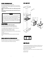
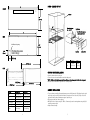
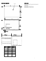
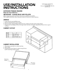
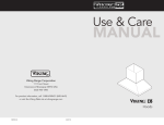
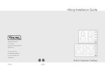
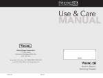
Viking Installation Guide
Viking Range Corporation
111 Front Street
Greenwood, Mississippi 38930 USA
(662) 455-1200
For product information,
call 1-888-VIKING1 (845-4641)
or visit the Viking Web site at
vikingrange.com
Designer Series Built-In Electric Warming Drawer
(DEWD Designer Model/DFWD Full Overlay Model)
F20022J EN
(022608J)
IMPORTANT - PLEASE READ AND FOLLOW
DEWD - CABINET CUTOUT
•Before beginning, please read these instructions completely and carefully.
•Do not remove permanently affixed labels, warnings, or plates from the product. This may void the warranty.
•Please observe all local ordinances. If local codes are applicable, wire in accordance with the National Electrical
Code, ANSI/NFPA 70 - latest edition.
•WARNING - To reduce the risk of electric shock and fire, do not use a flexible power-supply cord with this
appliance.
•The installer should leave these instructions with the consumer who should retain for local inspector’s use
and for future reference.
WARNING!!!
Make sure that incoming voltage is the same as unit rating. An electric rating plate specifying voltage,
hertz, wattage, amps, and phase is attached to the product. Wiring the warming drawer with more
voltage than it is rated for may cause severe damage to the thermostat, element, and other components.
Wiring the warming drawer with less voltage than it is rated for may cause significant decrease in
performance. To reduce the risk of fire, electric shock, or injury to persons, installation work and electrical
wiring must be done by qualified people in accordance with all applicable codes and standards, including
fire-rated conditions.
Cabinet
24”
(61.0 cm)
mounting screws (4) #8 x 3/4”
9 5/8”
(24.4 cm)
cavity
assy
drawer
assy
GENERAL INFORMATION
•THIS UNIT IS NOT TO BE INSTALLED BELOW CABINETS OR WALL MOUNTED.
•When installing this unit directly below other units, only install with Viking built-in products
•Remove warming drawer carefully from carton. Remove all loose packaging and accessories.
•It is the responsibility of the installer to comply with local codes. If no local codes are applicable, wire in
accordance with the National Electrical Code, ANSI/NFPA 70 - latest edition.
•This appliance is not fused. Protect with a proper sized fuse or circuit breaker.
•Line disconnect switch, circuit breaker, or plug/receptacle of power cord connection should be readily accessible
to the operator.
•Ground unit per applicable electrical codes.
•Any installation not matching the specifications discussed in these instructions will void the manufacturer’s
warranty.
ELECTRICAL CONNECTION - USE COPPER CONDUCTORS ONLY.
Model
A
DEWD170
25 1/4”
(64.1 cm)
DEWD100
28 1/4“
(71.8 cm)
With the appliance positioned in front of the cabinet opening, connect wire leads extending from the
power supply to the terminal block of the unit. Make sure the colored wires of the terminal block are
connected to the corresponding colored wires extending from the power supply.
CABINET INSTALLATION
•To remove drawer assembly, pull warming drawer pan out until fully extended. Slide finger along the right
and left side until you reach the black hand latches (located at the front of the rails). Pull up on both the
right and left latches and pull drawer pan support completely out.
•Slide cavity assembly into cabinet opening.
•Drill (4) pilot holes in cabinet using 1/8” drill bit. Permanently secure the warming drawer using the (4) #8
mounting screws provided.
•Replace drawer assembly.
2
3
DFWD - CABINET CUTOUT
B
FRONT
Cabinet
10”
(25.4 cm)
24”
(61.0 cm)
Mounting Screws
(4) - #8 x 3/4”
Cavity Assy.
(6) - #8 x 3/4” screws to
attach custom front
C
REAR
9 5/8”
(24.4 cm)
120V Electrical opening
9 1/2”
(24.1 cm)
2 1/2”
(6.4 cm)
insulation
custom front
2 1/2” (6.4 cm)
Model
27” (68.6 cm)
A
DFWD170
25 1/4”
(64.1 cm)
DFWD100
28 1/4”
(71.8 cm)
SIDE
CUSTOM FRONT INSTALLATION
1 1/2” (3.8 cm)
23” (58.4 cm)
22” (55.9 cm)
•Open the drawer and remove the pan.
•Center the custom front and insulation around the inside panel.
*NOTE: Make sure the insulation provided is used between the custom panel and the inside door panel.
•Attach the custom front with the (6) six #8 x 3/4” screws provided.
CABINET INSTALLATION
MODEL
DEWD170
DEWD100
B
26 1/2”(67.3 cm)
29 1/2” (74.9 cm)
C
24 7/8”(63.2 cm)
27 7/8” (70.8 cm)
Interior width
18 7/8 (47.9 cm)
21 7/8” (55.6 cm)
Interior height
5 7/16” (13.8 cm)
5 7/16” (13.8 cm)
Interior depth
21 3/16” (53.8 cm)
21 3/16” (53.8 cm)
Approx. shipping
Weight
80 lb. (36 kg)
90 lb. (40.5 kg)
4
•To remove drawer assembly, pull warming drawer pan out until fully extended. Slide finger along the right
and left side until you reach the black hand latches (located at the front of the rails). Pull up on both the
right and left latches and pull drawer pan support completely out.
•Slide cavity assembly into cabinet opening.
•Drill (4) pilot holes in cabinet using 1/8” drill bit. Permanently secure the warming drawer using the (4) #8
mounting screws provided.
•Replace drawer assembly.
5
CUSTOM PANEL DIMENSIONS
ELECTRIC DATA
3/4” thick
•Hard wire direct with separate 15 amp minimum 2-wire with ground circuit
•120 VAC/50-60 Hz
•DEWD170/DFWD170 - 425 watts/3.6 max. amps
•DEWD100/DFWD100 - 475 watts/4.0 max. amps
B
FRONT
10 1/2”
(26.7 cm)
C
REAR
120V Electrical opening
9 1/2”
(24.1 cm)
2 1/2”
(6.4 cm)
2 1/2” (6.4 cm)
21 7/8” (55.6 cm)
23 1/4” (58.7 cm)
MODEL
DFWD170
DFWD100
B
26”(66.0 cm)
29 ” (73.7 cm)
C
24 7/8”(63.2 cm)
27 7/8” (70.8 cm)
Interior width
18 7/8 (47.9 cm)
21 7/8” (55.6 cm)
Interior height
5 7/16” (13.8 cm)
5 7/16” (13.8 cm)
Interior depth
21 3/16” (53.8 cm)
21 3/16” (53.8 cm)
Approx. shipping
Weight
75 lb. (33.7 kg)
90 lb. (40.5 kg)
6
7