1
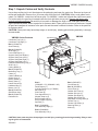
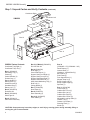
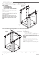
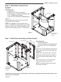
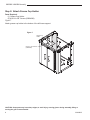
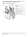
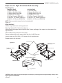
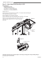
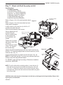
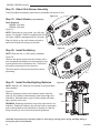
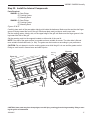
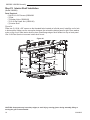
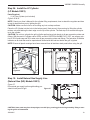
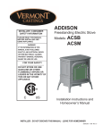
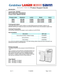
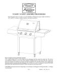
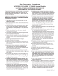
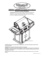
VM508K / VM658K Assembly Procedures
Knock Down Models
Tools Required: Knife or scissors, Phillips or Robertson (square head)
screwdriver, 7/16” and 3/8” wrench or ratchet. The use of a manual
screwdriver is strongly recommended. A power drill may cause damage
to the unit or stripping of the protective coating.
Model VM508K Shown
CAUTION: This grill is intended ONLY to be used as a cart model, this grill cannot be built
into an enclosure.
CAUTION: The assembly of this grill requires two (2) people.
WARNING: Some parts may have����������������
sharp edges; to avoid injury, wearing gloves during assem����
bly, lifting or moving the grill is recommended.
Protective eyewear and long sleeves are also
strongly recommended.
NOTE: Remove the protective plastic coating from the stainless steel, failure to do so will void the
warranty.
50004825 12/07 Rev. 3 En
VM508K / VM658K Assembly
ARRÊT !
STOP!
¡ALTO!
NO NEED TO RETURN TO THE STORE
Questions With The Assembly?
Require Parts Information?
Product Under Manufacturer’s Warranty?
PAS BESOIN DE RETOURNER AU
MAGASIN
NO ES NECESARIO QUE REGRESE A LA
TIENDA
Des questions sur l’assemblage?
De l’information sur les pièces?
Le produit est-il garanti par le fabricant?
¿Tiene alguna pregunta sobre el ensamble?
¿Necesita información sobre las partes?
¿El producto tiene garantía del fabricante?
Appelez-nous sans frais
États-Unis : 1-800-668-5323
Canada : 1-800-668-5323
Du lundi au vendredi, de 9 h
00 à 17 h 00 HNE
Call Toll-Free
Canada: 1-800-668-5323
USA: 1-800-668-5323
Monday to Friday 9:00 A.M. to
5:00 P.M. E.S.T.
Llame sin costo
Estados Unidos: 1-800-668-5323
Canadá: 1-800-668-5323
de lunes a viernes de 9:00 A.M. a
5:00 P.M. hora estándar del este
TO HELP US HELP YOU
Fill In The Information Below:
Retain This Owner’s Manual And Proof Of Purchase For Future Reference
POUR NOUS AIDER À VOUS AIDER
Veuillez remplir les données suivantes :
Conservez ce Manuel du propriétaire et preuve d’achat pour consultation ultérieure
PARA AYUDARNOS A AYUDARLE
Complete la siguiente información:
Guarde este Manual del usuario y Prueba de compra para futuras referencias
Model Number
Numéro du modèle
Número de modelo
Date of Purchase
Date d’achat
Fecha de compra
Product Serial No.
Numéro de série du produit
Número de serie del producto
MODEL NUMBER AND PRODUCT SERIAL NUMBER CAN BE FOUND ON THE CERTIFICATION LABEL OF YOUR GRILL
LE NUMÉRO DU MODÈLE ET LE NUMÉRO DE SÉRIE DU PRODUIT SE TROUVENT SUR L’ÉTIQUETTE DE CERTIFICATION
CAUTION: Some parts may have sharp edges;
avoidBARBECUE
injury, wearing gloves during assembly, lifting or
DEto
VOTRE
EL NÚMERO
DEisMODELO
Y EL NÚMERO DE SERIE DEL PRODUCTO SE ENCUENTRA EN LA ETIQUETA DE CERTIFImoving
the grill
recommended.
CACIÓN DE SU BARBACOA
2
50004825
VM508K / VM658K Assembly
Step 1: Unpack Carton and Verify Contents
Use a sharp cutting tool to cut the straps on the packaging and open the carton top. Remove top layers of
reinforced cardboard. Remove four (4) corner posts from main box. CAUTION: Heavy cook grates are located: For VM508K - inside front left corner post. For VM658K - inside rear left and rear right corner posts.
For both models, the gas line is located inside the front right side corner post. Remove the sleeve and
protective plastic coverings. Be careful not to scratch or damage the finish of the metal parts when removing the protective plastic. Refer to parts list for fastener detail. Open grill lid and remove the boxes. Unpack
all parts and compare all contents to the parts list and the carton contents list below. Refer to the parts list
for fastener detail.
CAUTION: Some parts may have sharp edges; to avoid injury, wearing gloves during assembly is strongly
recommended.
VM508K Carton Contents
Condiment Right
Condiment Tray Left (1)
Condiment Tray Right (1)
Box 1
Box 1 (50004673)
Sear Plates (4)
Box 2 (50004862)
Shelf Right (1)
Cover Side Burner (1)
Support Shelf Front Right (1)
Support Shelf Front Left (1)
Support Shelf Rear Right (1)
Support Shelf Rear Left (1)
Heat Shield Marinating Tray (1)
Shelf Left (1)
Cutting Board (1)
Box 3 (50004815)
Marinating Tray (1)
Caster (2)
Caster w/Brake (2)
Grease Cup (1)
Battery Holder (1)
Battery Case (1)
Handle Curved (2)
Hardware Bag (1)
Battery “AA” (1)
Box 4 (50004181)
Side Burner Assy
Box 5 (50004274)
Rotisserie Kit
VM508K
Condiment Left
Box 2
Box 7
Box 6
Box 4
Box 5
Box 3
Box 8
Box 10
Box 9
Box 6
(50004852 - LP) (50004854 - NG)
4825
Panel Bottom (1)
VM508K
Cylinder Retainer (1) (LP Model)
contents
Back Panel (1)
11/07
Side Panel (2)
Door Upper Brace (1)
Magnet Snap-in (2)
Brace Support Left (1)
Brace Support Right (1)
Spit Rod (1)
Box 7 (50004869)
Door Assembly Right (1)
Box 9 (50004672)
Cook Grates (3)
Box 10 (50004851)
Corner Post (4)
Cabinet Skirt Front (1)
Cabinet Skirt Left (1)
Cabinet Skirt Right (1)
Cabinet Skirt Corner (2)
Adjustable Leveling Glide (4)
Grease Tray (1)
Grease Cup Holder (1)
Warming Rack (1)
Knobs (5)
Box 8 (50004860)
Door Assembly Left (!)
CAUTION: Some parts may have sharp edges; to avoid injury, wearing gloves during assembly, lifting or moving the grill is recommended.
50004825
3
VM508K / VM658K Assembly
Step 1: Unpack Carton and Verify Contents (continued)
Condiment Right
Condiment Left
VM658K
Box 2
Box 1
Box 4
Box 3
Box 10
Box 5
Box 9
Box 6
Box 7
Box 8
Box 9
VM658K Carton Contents
Condiment Tray Right (1)
Condiment Tray Left (1)
Box 1 (50004815)
Marinating Tray (1)
Caster (2)
Caster w/Brake (2)
Grease Cup (1)
Battery Holder (1)
Battery Case (1)
Handle Curved (2)
Hardware Bag (1)
Battery “AA” (1)
Box 11
Box 5 (LP Model) (50004650)
Pull Out Tank Kit
Box 6 (50004794)
Shelf Right (1)
Cover Side Burner
(1)
����
Support Shelf Front Right (1)
���������������
Support Shelf Front Left (1)
�����
Support Shelf Rear
Right (1)
Support Shelf Rear Left (1)
Heat Shield Marinating Tray (1)
Shelf Left (1)
Cutting Board (1)
Box 10
(50004802 - LP) (50004881 - NG)
Panel Bottom (1)
Internal Shelf (1)
Hardware - Internal Shelf (1)
Back Panel (1)
Side Panel (2)
Door Upper Brace (1)
Magnet Snap-in (2)
Brace Support Left (1)
Brace Support Right (1)
Spit Rod (1)
Box 11 (50004796)
Corner Post (4)
Box 2 (50004274)
Cabinet Skirt Front (1)
Rotisserie Kit
Box 8 (50004763)
Cabinet Skirt Left (1)
Door Assembly (2)
Box 3 (50003669)
Cabinet Skirt Right (1)
Shelf Light Kit
Box 9 (2) (50004657)
Cabinet Skirt Corner (2)
Cook Grates (2)
Adjustable Leveling Glide (4)
Box 4 (50004181)
Grease Tray (1)
Side Burner Assembly
Grease Cup Holder (1)
Warming Rack (1)
Knobs (6)
CAUTION: Some parts may have sharp edges; to avoid injury, wearing gloves during assembly, lifting or
moving the grill is recommended.
4
Box 7 (50004792)
Sear Plates (5)
50004825
VM508K / VM658K Assembly
Step 2: Attach Casters to Bottom Panel
Parts Required:
(1) Bottom Panel
(2) Front Casters
(2) Rear Casters (w/Brake)
(16) 1/4-20 Nuts (50001176)
Figure 1
Front Caster
1/4-20 Nuts
(50001176)
Figure 1
Use top layer cardboard to protect floor and
parts from being scratched. Attach two (2) rear
casters (w/brake) to the back of the bottom
panel. (Fig. 5) Use four (4) nuts to secure each
caster to the bottom panel.
Attach two (2) front casters using four (4) nuts
to secure each caster to the bottom panel. Use
a 7/16” wrench or ratchet to tighten all nuts.
Rear Casters
w/Brake
Flange Down
B141
����
��������������
Step 3: Attach Four Metal Corner Posts to the Bottom
Panel
����
Parts Required:
(4) Corner Posts
(16) 1/4-20 x 5/8” Bolts (50000181)
Figure 2
Corner Post
NOTE: Remove protective layer from
corner posts.
1/4-20 x 5/8” Bolts
(50000181)
Figure 2
Loosely attach each corner post to the
corner of the bottom panel using four (4)
bolts each.
NOTE: Do not tighten all bolts at this
point.
Flange Down
B142
CAUTION: Some parts may have sharp edges; to avoid injury, wearing gloves during assembly, lifting or moving the grill is recommended.
50004825
5
����
�������������������
VM508K / VM658K Assembly
Step 4: Attach Brace Support to Metal Corner Post
Parts Required:
(1) Brace Support Left
(1) Brace Support Right
(8) #10-24 x 3/8” Screws (50004268)
Brace Support
Right
Front
#10-24 x 3/8” Screws
(50004268)
Figure 3
Attach brace support left to the top of the
metal corner post.
Front
Attach brace support right to the top of the
metal corner post.
NOTE: Be sure to attach the brace supports to the correct side. Refer to Figure 3.
Brace
Support Left
NOTE: Do not tighten all screws at this
point.
Figure 3
Re
ar
B143
Step 5: Attach Door Upper Brace to the Front of the Unit
Figure 4
Door Upper Brace
#10-24 x 3/8”
Screws
(50004268)
Parts Required:
����
(1)
Door Upper Brace
��������������������
(w/ two (2) magnets already attached)
����
(4)
#10-24 x 3/8” Screws (50004268)
NOTE: Remove protective layer from door upper brace.
Figure 4
Attach brace fascia to the front of the unit.
Make sure the brace fascia and front of the
metal corner posts are flush.
NOTE: Do not tighten all screws at this point.
B144 edges; to avoid injury, wearing gloves during assembly, lifting or
CAUTION: Some parts may have sharp
moving the grill is recommended.
50004825
6
����
�������������������
����
VM508K / VM658K Assembly
Step 6: Attach Back Panel & Tank
Support
Parts Required:
(1) Back Panel
(4) #10-24 x 3/8” Screws (50004268)
(1) Tank Retainer (LP Model) (VM508K Model)
(1) 1¹⁄₂” OD Bushing (NG Model)
Back Panel
(1) Pull Out Tank (LP Model) (VM658K Model)
Figure 5
Attach back panel to the back of the unit using
four (4) #10-24 x 3/8” screws.
#10-24 x
3/8” Scres
(50004268)
Tank Retainer
(LP Models)
NOTE: For VM508K LP models, attach tank retainer. For VM658K LP models attach pull out tank
assembly. (Follow Pull Out Tank assembly instrucitons) For all NG models, attach 1¹⁄₂” OD bushing.
Figure 5
1¹⁄₂” OD Bushing
(Natural Gas
Models)
B145
Step 7: Attach Door Assembly and Door Handle
Caution Label
Door Assembly
Handle
w/Screws
Figure 6
CA
UT
IO
N
����
Parts
Required:
�����������������
(2)
���� Door Assemblies
(2) Door Handles (w/ Mounting Screws)
(8) #10-24 x 3/8” Screws (50004268)
M
IS
E
EN
GA
RD
E
Attach one (1) door handle to each door assembly using two (2) screws provided with
the handle.
CU
ID
AD
O
Back
Panel
NOTE: Door with caution label - right side.
Attach door assembly with door handle to
the front left and front right cabinet corner
posts.
Make sure the unit is on a level surface.
#10-24 x 3/8” Screws
(50004268)
Align top and bottom of the doors.
NOTE: Fully tighten all bolts and screws
from Steps 3 through 7.
Routing for
Natural Gas
Supply Hose
to House
Figure 6
B146
CAUTION: Some parts may have sharp edges; to avoid injury, wearing gloves during assembly, lifting or mov����
ing the grill is recommended.
50004825
��������������������
����
7
VM508K / VM658K Assembly
Step 8: Attach Grease Cup Holder
Parts Required:
(1) Grease Cup Holder
(2) #10-24 x 3/8” Screws (50004268)
Figure 7
Attach grease cup holder to the bottom of the left brace support.
Figure 7
Grease Cup
Holder
#10-24 x 3/8” Screws
(50004268)
B147
����
������������������������
����
CAUTION: Some parts may have sharp edges; to avoid injury, wearing gloves during assembly, lifting or
moving the grill is recommended.
8
50004825
VM508K / VM658K Assembly
Step 9: Attach Skirt
Parts Required:
(1) Skirt Left Assembly
(1) Skirt Right Assembly
(1) Skirt Front Assembly
(2) Skirt Corner Assemblies
(7) #10-24 x 3/8” Screws (50004268)
(4) Adjustable Leveling Glide
Leveling Glide
Figures 8 & 9
Screw-in two (2) adjustable leveling glides into
hex threaded insert provided in front skirt assembly.
Screw-in one (1) adjustable leveling glide into
hex threaded insert provided in left and right skirt
assemblies.
Skirt Front Assembly
Skirt Left Assembly
Skirt Right Assembly
Figure 8
Inverted View
B148
Attach left skirt assembly to the unit:
– Loosen one hex bolt from corner post. (Refer to Corner Post Detail)
– Place left skirt assembly on the top of the bottom panel,
����
– Secure left skirt assembly with two (2) #10-24 x 3/8” screws.��������������
– Tighten hex bolt at the back of the unit.
����
Figure 9
Repeat these steps for right side.
Slide two (2) skirt corner assemblies into the front
skirt assembly. Slide above assembly into attached left and right skirt assemblies. Secure
all skirt assembly parts with three (3) #10-24 x
3/8” screws.
Skirt Left
Assembly
Corner Post Detail
#10-24 x
3/8” Screw
(50004268)
Loosen Outer
Bolt at Back Side
B149
Skirt Front Assembly
Skirt Right
Assembly
Skirt Corner Assembly
CAUTION: Some parts may have sharp edges; to avoid injury, wearing gloves during assembly, lifting or moving the grill is recommended.
50004825
����
������������
����
9
VM508K / VM658K Assembly
Step 10: Attach Side Panels
Parts Required:
(2) Side Panels
(8) #10-24 x 3/8” Screws (50004268)
Figure 10
Side Panel
NOTE: Remove protective layer from side panels.
Figure 10
Place side panel, with cutout at bottom, against two
(2) corner posts.
Secure side panel using four (4) screws.
Repeat for opposite side.
Make sure the two (2) openings (cut-outs) are at the
bottom.
#10-24 x 3/8”
Screws
(50004268)
B150
Step 11:
Attach Grease Catching Components
Parts Required:
(1) Grease Cup
(1) Grease Tray
Grease Tray
Figure 11
Grease Cup
Figure 11
Place grease cup into provided grease
cup holder.
Place grease tray into provided channels
and slide above grease cup until grease
tray locks into grooves inside left and right
brace.
�����
������������������
����
B151
CAUTION: Some parts may have sharp edges; to avoid injury, wearing gloves during assembly, lifting or
moving the grill is recommended.
50004825
10
����
�����������������
VM508K / VM658K Assembly
Step 12: Attach Grill to Cabinet Assembly
CAUTION: This step requires a minimum of 2
people.
Figure 12
Parts Required:
(8) 1/4-20 x 1/2” Screws (50000913)
Figure 12
Tilt the grill to move gas line from underneath
main console.
Lift grill above cabinet assembly.
Locate gas line inside cabinet assembly, between door fascia and grease tray.
1/4-20 x 1/2”
Screws
(50000913)
Place grill on cabinet assembly. CAUTION: Do
not damage gas line.
Align threaded nuts with slots.
Secure grill to cabinet with four (4) screws per
side.
B249
����
������������
�����
CAUTION: Some parts may have sharp edges; to avoid injury, wearing gloves during assembly, lifting or moving the grill is recommended.
50004825
11
VM508K / VM658K Assembly
Step 13a: Secure Hose to Upper Door Brace
(Model VM508K)
Parts Required:
(1) Hose Bracket
(2) #6-32 x 3/8” Screws (50002433)
Figure 13a
Attach hose bracket to the door upper brace with two (2) #6-32 x 3/8” screws.
Door Upper Brace
Figure 13a
Hose Bracket
#6-32 x 3/8” Screws
(50002433)
B250
Step 13b: Secure Hose to the Cabinet
����
Figure 13
Gas Line Clamp Detail
Figure 13b
������������
�����
Remove second screw from top. (Screws which
were attached
in Step 7) (right door) (Fig. 13)
Gas Line
Hose
Place clamp on the hose.
Re-attach removed screw.
Right Door
Gas Line Clamp
B176
����
CAUTION: Some parts may have sharp edges; to avoid injury, wearing gloves during
assembly, lifting or
�����������������
moving the grill is recommended.
����
12
50004825
VM508K / VM658K Assembly
Steps 14 & 15: Right & Left Side Shelf Assembly
Parts Required:
Right Side Shelf
(1) Right Side Shelf
(1) Support Shelf Rear Right
(1) Support Shelf Front Right
(1) Condiment Tray Right
(2) U-Type Fastener (50001507)
(2) #10-24 x 1/2” Screws (50000337)
(4) #6-32 x 3/8” Screws (50002433)
Left Side Shelf
(1) Left Side Shelf
(1) Support Shelf Rear Left
(1) Support Shelf Front Left
(1) Condiment Tray Left
(2) U-Type Fastener (50001507)
(2) #10-24 x 1/2” Screws (50000337)
(4) #6-32 x 3/8” Screws (50002433)
NOTE: Remove protective layer from left and right shelf.
Figure 14
Right Side Shelf
Insert a U-type fastener to each support shelf.
Place right side shelf on flat surface edges up.
Slide left and right support inside right side shelf. Ensure the flange of the support is to the inside of the
right side shelf.
Place condiment tray at the front of the shelf.
Secure condiment tray to the support shelf with four (4) #6-32 screws.
Loosely attach two (2) #10-24 x 1/2” screws to the U-type fasteners.
Repeat steps for left side shelf.
Condiment Trays
Figure 14
#6-32 x 3/8” Screw
(50002433)
#10-24 x 1/2” Screws
(50000337)
U-Type Fastener
Support Shelf
Front
B160
U-Type Fastener Detail
Right Side Shelf
Left Side Shelf
U-Type Fastener
CAUTION: Some parts may have sharp edges; to avoid injury, wearing gloves during assembly, lifting or moving the grill is recommended.
����
50004825
����������������
����
13
VM508K / VM658K Assembly
Step 16: Attach Right Shelf Assembly to Grill
Parts Required:
Right Shelf Assembly
(1) Right Shelf Assy. (Step 5)
(4) 1/4-20 x 1¹⁄₂” Screws (50001383)
(2) #10-24 x 1/2” Screws (50000337)
Figures 15 & 16
Loosely screw in (4-5 turns) four (4) 1/4-20 x 1¹⁄₂” screws to the side of the grill.
Place right shelf assembly onto screws.
Secure (tighten) four (4) screws to the grill.
Secure condiment tray to the console with two (2) #10-24 x 1/2” screws.
Tighten two (2) remaining screws. (from Steps 14 and 15)
Figure 15
From inside grill, attach 10-24 x 1/2” screw to the right
shelf assy.
#10-24 x 1/2”
Screws
(50000337)
1/4-20 x 1¹⁄₂”
Screws
(50001383)
B161
Figure 16
#10-24 x 1/2” Screw
(50000337)
����
��������������
����
B180
����
������������
CAUTION: Some parts may have sharp edges; to avoid injury, wearing gloves during assembly, lifting or
����
moving the grill is recommended.
14
50004825
VM508K / VM658K Assembly
Step 17: Attach Left Shelf Assembly to Grill
Parts Required:
Left Shelf Assembly
(1) Left Shelf Assy. (Step 6)
(4) 1/4-20 x 1¹⁄₂” Screws (50001383)
(4) #10-24 x 1/2” Screws (50000337)
(1) Marinating Station Tray Plastic
(1) Heat Shield Marinating Tray
(2) #10-24 K-lock Nut (50000182)
#10-24 K-lock Nuts
(50000182)
Refer to Figures 15 & 16 for shelf assembly attachFigure 17
ment
Refer to Figures 17 & 18 for heat shield and marinating station installation
Loosely screw in (4-5 turns) four (4) 1/4-20 x 1¹⁄₂”
screws to the side of the grill.
Place left shelf assembly onto screws.
Secure (tighten) four (4)
screws to the grill.
Secure condiment tray
to the console with
two (2) #10-24 x 1/2”
screws.
#10-24 x 1/2” Screws
(50000337)
Heat Shield
Marinating Tray
Tighten two (2) remaining screws. (from Step
15 and 16)
From inside grill, attach
10-24 x 1/2” screw to
the left shelf assy.
B183
Attach heat shield marinating tray to left side of grill. Insert two (2)
#10-24 x 1/2” screws through grill side and secure with two (2) #10����
24 K-lock nuts. (Fig. 17)
������������������
����
Insert marinating station tray plastic into left side shelf. (Fig. 18)
Figure 18
Marinating
Tray
NOTE: For side shelf opening: if you have any problems opening or
closing, loosen the hinge bolts and adjust.
For VM658K, install shelf light according to Electronics Installation
Instructions, #50003699.
NOTE: For grill models with a marinating station: Loosen the two (2)
bolts and nuts securing the heat shield marinating tray to the grill
body. (Fig. 17) Attach the rotisserie motor bracket using the same
mounting holes. Secure both the bracket and heat shield using bolts
and nuts provided.
CAUTION: Some parts may have sharp edges; to avoid injury, wearing gloves during assembly, lifting or moving the grill is recommended.
50004825
15
VM508K / VM658K Assembly
Step 18: Attach Side Burner Assembly
Follow Side Burner Assembly Instructions to assemble side burner to unit.
Figure 19
Step 19: Attach Knobs (If not installed)
Parts Required:
VM508K: (5) Knobs
VM658K: (6) Knobs
Figure 19
NOTE: Depending on your model, your grill may
require 5 or 6 knobs. VM508 is equipped with five
(5) knobs. VM658 is equipped with six (6) knobs.
B177
Align the knobs on the valve stems and push inward until the knob sits snugly on the stem.
Figure 20
Step 20: Install the Battery
NOTE: Requires one (1) “AA” battery. (supplied)
Figure 20
Unscrew the ignition button from the console and insert the appropriate battery into the housing by placing the positive side of the battery first. Then screw
the ignition button back into the console.
����
������������
����
Check for sparks under each main burner before
proceeding.
�
�
B178
Step 21: Install the Backlighting Batteries
Figure 21
NOTE: Eight (8) “AA” batteries are required for all grill models.
(Not included)
����
Figure 21
���������������
Remove the battery case from the battery holder. Insert the ���� Battery
Case
eight (8) “AA” batteries. Attach battery case to back light wire
connection. Reinstall battery case in battery holder with back
light connector on the top.
Battery Shroud
WARNING: Replacing the battery incorrectly might result in an
explosion. Replace the battery only with the same or equivalent
type recommended by the manufacturer. Dispose of used batteries according to your local environmental guidelines.
B245
CAUTION: Some parts may have sharp edges; to avoid injury, wearing gloves during assembly, lifting or
moving the grill is recommended.
16
50004825
����
������������
�����
VM508K / VM658K Assembly
Step 22: Install the Internal Components
Parts Required:
VM508K: (4) Sear Plates
(3) Cooking Grates
(1) Warming Rack
VM658K: (5) Sear Plates
(4) Cooking Grates
(1) Warming Rack
Figures 22 & 23
Carefully place each of the sear plates side by side inside the barbecue. Make sure the semicircular finger
groove is facing toward the front of the grill. Each sear plate rests just above each burner tube.
Set the cooking grates, side by side, on the upper ledge of the grill tub. Make sure the finger groove is facing toward the front of the grill.
Set the warming rack into the supports located on either side of the rear lid.
NOTE: One side of the grate surface is rounded and more suitable for meats. The other side is flat and
more suitable for delicate foods (i.e. fish). The grates can be turned over according to your preference.
CAUTION: Do not attempt to turn the cooking grates over while the grill is in use and the grates are hot.
Doing so could result in severe burns and other injuries.
Figure 23
Warming
Rack
Figure 22
Burner
Sear Plate
B251
Cooking
Grates
B120
����
�����������
����
����
����������������
�����
CAUTION: Some parts may have sharp edges; to avoid injury, wearing gloves during assembly, lifting or moving the grill is recommended.
50004825
17
VM508K / VM658K Assembly
Step 23: Interior Shelf Installation
(Model VM658K)
Parts Required:
(2) #10-24 x 3/8” Screws (50004268
(1) Rod
(1) Washer Nylon (50000192)
(1) 10-24 Pan Quad. Nut (10006126)
(1) Interior Shelf
Figure 24
Place two (2) 10-24 x 3/8” screws on the threaded holes located on left side panel. Install the rod in hole
in bottom panel. Make sure the connection between the rod and the bottom panel is tight. Place washer
nylon on top of rod. Slide interior shelf in place. Back flange edge of shelf slides into clip on back panel.
Use 10-24 Pan Quad nut to secure interior shelf to rod.
Figure 24
Interior Shelf
#10-24 Pan Quad Nut
Shelf clip
#10-24 x 3/8” Screw
(50004268)
Rod
B162
����
����������������������
����
CAUTION: Some parts may have sharp edges; to avoid injury, wearing gloves during assembly, lifting or
moving the grill is recommended.
18
50004825
VM508K / VM658K Assembly
Step 24: Install the LP Cylinder
(LP Models ONLY)
Parts Required:
(1) LP Gas Cylinder (not included)
Figures 25 & 26
NOTE: Check your User’s Manual for the cylinder filling requirements, how to attach the regulator and how
to test for leaks before you try lighting the grill.
CAUTION: Make sure the hose is not touching any hot or sharp surfaces.
Place the LP Cylinder into the hole in the bottom panel. Next secure it from moving by lifting the cylinder
retainer wire and latching the bent edge over the lip of the cylinder. The final step is to connect the regulator to the cylinder.
CAUTION: Do not turn on/ignite the grill until after performing a leak check at all gas connection points and
fittings. With the main LP cylinder valve OPEN, and ALL CONTROL KNOBS FULLY OFF, use a spray solution of 50% liquid soap and 50% water onto all gas connection points and fittings. The formation of bubbles
indicates an air leak that must be repaired and verified with this leak test before the grill is ignited.
NOTE: Ensure all plastic coatings have been removed from all stainless steel parts before using the grill.
Figure 26
Figure 25
B120
B119
Step 19: Install Natural Gas Supply Line
���� Models ONLY)
(Natural Gas (NG)
Figure 27
������������
����
Run natural gas supply lne through bushing provided in back panel of grill.
Figure 27
����
��������������
����
B240
CAUTION: Some parts may have sharp edges; to avoid injury, wearing gloves during assembly, lifting or moving the grill is recommended.
50004825
19
����
CFM Corporation
2695 Meadowvale Blvd. • Mississauga, Ontario, Canada L5N 8A3
800-668-5323 • www.cfmcorp.com