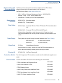
1
Vx810
Installation Guide
VeriFone Part Number 24963, Revision B
Vx810 Installation Guide
© 2008 VeriFone, Inc.
All rights reserved. No part of the contents of this document may be reproduced or transmitted in any form without the written
permission of VeriFone, Inc.
The information contained in this document is subject to change without notice. Although VeriFone has attempted to ensure the
accuracy of the contents of this document, this document may include errors or omissions. The examples and sample programs are
for illustration only and may not be suited for your purpose. You should verify the applicability of any example or sample program
before placing the software into productive use. This document, including without limitation the examples and software programs, is
supplied “As-Is.”
VeriFone, the VeriFone logo, Omni, VeriCentre, Verix, and ZonTalk are registered trademarks of VeriFone. Other
brand names or trademarks associated with VeriFone’s products and services are trademarks of VeriFone, Inc.
All other brand names and trademarks appearing in this manual are the property of their respective holders.
Comments? Please e-mail all comments in this document to your local VeriFone Support Team.
VeriFone, Inc.
2099 Gateway Place, Suite 600
San Jose, CA, 95110 USA
www.verifone.com
VeriFone Part Number 24963, Revision B
CONTENTS
PREFACE . . . . . . . . . . . . . . . . . . . . . . . . . . . . . . . . . . . . . . . 3
Audience. . . . . . . . . . . . . . . . . . . . . . . . . . . . . . . . . . . . . . . . . . . . . . . . . . . . . . . .
Organization . . . . . . . . . . . . . . . . . . . . . . . . . . . . . . . . . . . . . . . . . . . . . . . . . . . . .
Related Documentation . . . . . . . . . . . . . . . . . . . . . . . . . . . . . . . . . . . . . . . . . . . .
Guide Conventions . . . . . . . . . . . . . . . . . . . . . . . . . . . . . . . . . . . . . . . . . . . . . . . .
Acronym Definitions . . . . . . . . . . . . . . . . . . . . . . . . . . . . . . . . . . . . . . . . . . . .
3
3
3
4
4
CHAPTER 1
Overview Vx810 PIN pad . . . . . . . . . . . . . . . . . . . . . . . . . . . . . . . . . . . . . . . . . . . . . . . . . . . 7
Features at a Glance . . . . . . . . . . . . . . . . . . . . . . . . . . . . . . . . . . . . . . . . . . . . . . 7
Features and Benefits . . . . . . . . . . . . . . . . . . . . . . . . . . . . . . . . . . . . . . . . . . . . . 8
CHAPTER 2
Setup Select Location . . . . . . . . . . . . . . . . . . . . . . . . . . . . . . . . . . . . . . . . . . . . . . . . . . . 9
Ease of Use . . . . . . . . . . . . . . . . . . . . . . . . . . . . . . . . . . . . . . . . . . . . . . . . . . 9
Environmental Factors . . . . . . . . . . . . . . . . . . . . . . . . . . . . . . . . . . . . . . . . . . 9
Electrical Considerations . . . . . . . . . . . . . . . . . . . . . . . . . . . . . . . . . . . . . . . 10
Unpack Shipping Carton. . . . . . . . . . . . . . . . . . . . . . . . . . . . . . . . . . . . . . . . . . . 10
Examine
Vx810 Features. . . . . . . . . . . . . . . . . . . . . . . . . . . . . . . . . . . . . . . . . . . . . . . . . . 11
Install/Replace MSAM Cards . . . . . . . . . . . . . . . . . . . . . . . . . . . . . . . . . . . . . . . 12
Privacy Shield. . . . . . . . . . . . . . . . . . . . . . . . . . . . . . . . . . . . . . . . . . . . . . . . . . . 14
Cable Connections . . . . . . . . . . . . . . . . . . . . . . . . . . . . . . . . . . . . . . . . . . . . . . . 14
Connection to another VeriFone Terminal . . . . . . . . . . . . . . . . . . . . . . . . . . 15
RS232 Connection using an External Power Brick. . . . . . . . . . . . . . . . . . . . 15
Direct USB Connection . . . . . . . . . . . . . . . . . . . . . . . . . . . . . . . . . . . . . . . . . 16
USB–Download Support using an External Power Brick . . . . . . . . . . . . . . . 16
Terminal using a PoweredUSB connection . . . . . . . . . . . . . . . . . . . . . . . . . 16
Ethernet Connection with External Power Brick . . . . . . . . . . . . . . . . . . . . . . 17
Power Supply . . . . . . . . . . . . . . . . . . . . . . . . . . . . . . . . . . . . . . . . . . . . . . . . . . . 17
Smart Card Reader Use . . . . . . . . . . . . . . . . . . . . . . . . . . . . . . . . . . . . . . . . . . . 18
Magnetic Card Reader Use . . . . . . . . . . . . . . . . . . . . . . . . . . . . . . . . . . . . . . . . 18
To Conduct a Credit/Debit Card Transaction . . . . . . . . . . . . . . . . . . . . . . . . 18
Contactless Module . . . . . . . . . . . . . . . . . . . . . . . . . . . . . . . . . . . . . . . . . . . . . . 19
Installing the Vx810 CTLS Module . . . . . . . . . . . . . . . . . . . . . . . . . . . . . . . . 19
Using the Vx810 CTLS Module . . . . . . . . . . . . . . . . . . . . . . . . . . . . . . . . . . . 21
C H A P T E R 3 Specifications . . . . . . . . . . . . . . . . . . . . . . . . . . . . . . . . . . . . . . . . . . . . . . . . . . . 23
Unit Power Requirements . . . . . . . . . . . . . . . . . . . . . . . . . . . . . . . . . . . . . . .
Power Pack. . . . . . . . . . . . . . . . . . . . . . . . . . . . . . . . . . . . . . . . . . . . . . . . . .
Temperature . . . . . . . . . . . . . . . . . . . . . . . . . . . . . . . . . . . . . . . . . . . . . . . . .
Humidity . . . . . . . . . . . . . . . . . . . . . . . . . . . . . . . . . . . . . . . . . . . . . . . . . . . .
External Dimensions . . . . . . . . . . . . . . . . . . . . . . . . . . . . . . . . . . . . . . . . . . .
Weight. . . . . . . . . . . . . . . . . . . . . . . . . . . . . . . . . . . . . . . . . . . . . . . . . . . . . .
23
23
23
23
23
23
VX810 INSTALLATION GUIDE
1
C ONTENTS
CHAPTER 4
Maintenance and Clean the PIN Pad. . . . . . . . . . . . . . . . . . . . . . . . . . . . . . . . . . . . . . . . . . . . . . . 25
Cleaning Card Readers . . . . . . . . . . . . . . . . . . . . . . . . . . . . . . . . . . . . . . . . . . . . . . . . . . . 25
CHAPTER 5
Service and Support Service Returns . . . . . . . . . . . . . . . . . . . . . . . . . . . . . . . . . . . . . . . . . . . . . . . . . 27
Accessories and Documentation . . . . . . . . . . . . . . . . . . . . . . . . . . . . . . . . . . . .
Supplementary Hardware . . . . . . . . . . . . . . . . . . . . . . . . . . . . . . . . . . . . . . .
Data Cables . . . . . . . . . . . . . . . . . . . . . . . . . . . . . . . . . . . . . . . . . . . . . . . . .
Power Supply . . . . . . . . . . . . . . . . . . . . . . . . . . . . . . . . . . . . . . . . . . . . . . . .
Power Cord . . . . . . . . . . . . . . . . . . . . . . . . . . . . . . . . . . . . . . . . . . . . . . . . . .
Cleaning Kit. . . . . . . . . . . . . . . . . . . . . . . . . . . . . . . . . . . . . . . . . . . . . . . . . .
Contactless Module . . . . . . . . . . . . . . . . . . . . . . . . . . . . . . . . . . . . . . . . . . .
Documentation . . . . . . . . . . . . . . . . . . . . . . . . . . . . . . . . . . . . . . . . . . . . . . .
29
29
29
29
29
29
29
29
CHAPTER 6
Troubleshooting Blank Display . . . . . . . . . . . . . . . . . . . . . . . . . . . . . . . . . . . . . . . . . . . . . . . . . . . 31
Guidelines Keypad Does Not Respond . . . . . . . . . . . . . . . . . . . . . . . . . . . . . . . . . . . . . . . . 31
Transactions Fail To Process . . . . . . . . . . . . . . . . . . . . . . . . . . . . . . . . . . . . . . . 32
2
VX810 INSTALLATION GUIDE
PREFACE
This guide is the primary source of information for setting up and installing Vx810.
Audience
This guide provides simple descriptions of Vx810 features, as well as basic
information for the installation and configuration of the Vx810.
Organization
This guide is organized as follows:
Chapter 1, Overview. Provides an overview of the Vx810.
Chapter 2, Setup. Explains setup and installation of Vx810, selecting a location
and establishing connections with other devices.
Chapter 3, Specifications. Discusses power requirements and dimensions of the
Vx810.
Chapter 4, Maintenance and Cleaning. Explains maintenance of the Vx810.
Chapter 5, Service and Support. Provides information on contacting your
VeriFone service provider and information on how to order accessories or
documentations from VeriFone.
Chapter 6, Troubleshooting Guidelines. Provides troubleshooting guidelines
should you encounter a problem in terminal installation and configuration.
Related
Documentation
To learn more about Vx810, refer to the following set of documents:
Vx810 Certification and Regulation Sheet
VPN 24960
Vx810 Quick Installation Guide
VPN 24961
Vx810 Reference Guide
VPN 24964
Vx810 Privacy Shield Quick Installation Guide
VPN 24965
Vx810 Stand Adapter Quick Installation Guide
VPN 24966
Vx810 CTLS Quick Installation Guide
VPN 28601
VX810 INSTALLATION GUIDE
3
P REFACE
Guide Conventions
Guide
Conventions
Various conventions are used to help you quickly identify special formatting.
Table 1 describes these conventions and provides examples of their use.
Table 1
Convention
Document Conventions
Meaning
Example
Blue
Text in blue indicates terms that
are cross references.
See Guide Conventions.
Italics
Italic typeface indicates book
titles or emphasis.
You must not use this unit
underwater.
NOTE
The pencil icon is used to
highlight important information.
RS232-type devices do not work
on the Vx810 communication
port.
CAUTION
The caution symbol indicates
hardware or software failure, or
loss of data.
The unit is not waterproof or
dustproof, and is intended for
indoor use only.
WARNING
The lighting symbol is used as a
warning when bodily injury might
occur.
Due to risk of shock do not use
the terminal near water.
Acronym Definitions Various acronyms are used in place of the full definition. Table 2 presents
acronyms and their definitions.
Table 2
4
VX810 INSTALLATION GUIDE
Acronym Definitions
Acronym
Definitions
AES
Advanced Encryption Standard Algorithm
API
Application Programming Interface
ARM
Advanced RISC Machines
CAPK
Certification Authority Public Key as in the EMV standard
CBC
Cipher Block Chaining mode, as defined in ANSI X3.106
COG
Chip on Glass
COGS
Cost of Goods Sold
CTS
Clear to Send
DEA/DES
Data Encryption Algorithm/Standard, as defined in ANSI X3.92
DUKPT
Derived Unique Key Per Transaction Method as defined in the
VISA’s POS Equipment Requirement: PIN processing and Data
Authentication, International Version 1.0, August 1988
ECB
Electronic Code Book mode, as defined in ANSI X3.106
ECR
Electronic Cash Register
EMV
Joint Europay, MasterCard and Visa Standard
ERS
Engineering Requirements Specification
P REFACE
Guide Conventions
Table 2
Acronym Definitions (continued)
Acronym
Definitions
GID
Group Identifier - Concept inherited from Verix terminals file
system
HDLC
High-level Data Link Control
ICC
Integrated Chip Card (Smart Card)
LCD
Liquid Crystal Display
MAC
Message Authentication Code, as defined in ANSI X9.19
MMU
Memory Management Unit
MSAM
Multiple Secure Access Module
MSR
Magnetic Stripe Reader
OS
Operating System
PED
PIN Entry Device
PIN
Personal Identification Number
POS
Point-of-Sale
PRD
Product Requirement Document
PSCR
Primary Smart Card Reader
RFID
Radio Frequency Identification
RTS
Ready to Send
SOC
System on Chip
SAM
Secure Access Module
SC
Smart Card (Integrated Chip Card)
SD
Secure Digital
SDK
Software Development Kit
SL3
Security Level 3 and 4
SR
Ship Release
SRAM
Static Random Access Memory
STN
Super Twisted Nematic
UI
User Interface
USB
Universal Serial Bus
VSS
VeriShield Security Scripts
VX810 INSTALLATION GUIDE
5
P REFACE
Guide Conventions
6
VX810 INSTALLATION GUIDE
CHAPTER 1
Overview
This chapter provides a brief description of VeriFone’s Vx810.
Vx810 PIN pad
The Vx810 is a PIN pad with an integrated smart card reader for connection to
either VeriFone transaction terminals or third party electronic point-of-sale
systems, offering advanced security and smart card processing capabilities.
The Vx810 series supports both symmetric encryption algorithms (DES, 3DES,
and AES) and asymmetric encryption (RSA). This device internally manages
simultaneous multiple keys through either Master Session- or DUKPT-based
processes, and offers high performance smart card processing, as well as support
for the new generation of 3-volt cards.
The Vx810 is a programmable device, allowing a custom or EMV-approved
transaction application to run from the VISA PCI-compliant PIN pad, either to
meet local regulatory requirements or relieve the ECR or terminal of this task.
Features at a
Glance
The Vx810 has a sleek and stylish ergonomic design that offers power and
performance in a smart card- or MSR-integrated PIN pad device. The Vx810
provides the right combination of features and functions in a sleek, stylish device
that fits in the palm of your hand. This includes a magnetic stripe card reader,
smart card reader, and integrated PIN pad.
• Delivers power and usability in a
convenient hand-held design.
• Securely supports and runs payment
and value-added applications.
• Offers unsurpassed performance on
EMV smart card transactions.
• Security architecture meets
specifications for PIN-entry devices
(PCI) and sophisticated file
authentication.
Figure 1
Vx810 with new handheld design
VX810 INSTALLATION GUIDE
7
O VERVIEW
Features and Benefits
Features and Exceptional Ease of Use
Benefits • Bold, ergonomic design is sleek, stylish, and lightweight for conveniently
handing the unit to the consumer for PIN entry or other input.
•
Intuitive telco-style interface and large, colored control keys simplify training
and reduce support requests.
•
Highly readable display handles multiple languages for global applications.
Critical Security Protection
•
Incorporates tamper-detection circuitry to resist unauthorized intrusion and
supports a broad spectrum of software-based security features.
•
Integrated security modules simultaneously support sophisticated encryption
(AES, DES, 3DES, RSA) and key management schemes, including single and
3DES Master Session, single, and 3DES Derived.
Strong Feature Set
•
Ensures uncompromising reliability from VeriFone, the worldwide leader in
e-payment.
•
Primary smart card reader support for synchronous and asynchronous smart
cards.
•
Support for international character sets and Unicode standard.
•
The Vx810 received EMV Level 1 approval for smart card solutions.
•
VeriShield security architecture provides sophisticated file authentication to
prevent execution of unauthorized software on the Vx810.
Extended PIN pad Capabilities
8
VX810 INSTALLATION GUIDE
•
Optional privacy shield.
•
Display backlighting for use in low-light or high-glare environments.
•
Triple-track, high-coercivity card reader handles most magnetic stripe cards.
•
Three Security Access Modules (SAMs) safeguard sensitive financial data
and support multiple smart card schemes.
•
Optional contactless module enhancement.
•
Can be combined with Vx810 DUET to provide a complete counter top
payment solution.
•
Can be powered by other Vx series terminals through the multi-connector
cable.
CHAPTER 2
Setup
This chapter describes the setup procedure for Vx810, in the following sections:
Select Location
•
Select Location
•
Unpack Shipping Carton
•
Examine Vx810 Features
•
Install/Replace MSAM Cards
•
Privacy Shield
•
Cable Connections
•
Power Supply
•
Smart Card Reader Use
•
Magnetic Card Reader Use
Use the following guidelines to select a location for the Vx810.
Ease of Use •
Select a location convenient for both merchant and cardholder.
•
Select a flat support surface, such as a countertop or table.
•
Select a location near a power outlet and the terminal, ECR, or computer
connected to the Vx810. For safety, do not string cables or cords across a
walkway.
Environmental •
Factors
CAUTION
Do not use the unit where there is high heat, dust, humidity, moisture, or
caustic chemicals or oils.
•
Keep the unit away from direct sunlight and anything that radiates heat, such
as a stove or a motor.
•
Do not use the Vx810 outdoors.
The Vx810 is not waterproof or dustproof, and is intended for indoor use only.
Any damage to the unit from exposure to rain or dust can void any warranty.
VX810 INSTALLATION GUIDE
9
S ETUP
Unpack Shipping Carton
Electrical •
Considerations •
•
Avoid using this product during electrical storms.
Avoid locations near electrical appliances or other devices that cause
excessive voltage fluctuations or emit electrical noise (for example, air
conditioners, electric motors, neon signs, high-frequency or magnetic security
devices, or computer equipment).
Do not use the Vx810 near water or in moist conditions.
WARNING Due to risk of shock or damage, do not use the Vx810 near water, including a
bathtub, wash bowl, kitchen sink or laundry tub, in a wet basement, or near a
swimming pool.
Unpack
Shipping Carton
Open the shipping carton and carefully inspect its contents for possible tampering
or shipping damage. The Vx810 is a secure product and any tampering can cause
it to cease to function or to operate in an unsecured manner.
1 Remove and inspect the contents of the shipping carton, since the Vx810
ships in multiple configurations, the carton may include any or all of the
following:
•
Vx810
•
Data cable
•
Power pack
•
Power cord
•
ECR cable
•
Privacy shield
2 Remove all plastic wrapping from the terminal and components.
3 Remove the clear protective film from the display.
4 Save the shipping carton and packing material for future repacking or moving
of the device.
WARNING Do not use a unit that has been tampered with or damaged.
The Vx810 comes equipped with tamper-evident labels. If a label or component
appears damaged, please notify the shipping company and your VeriFone
service provider immediately.
10
VX810 INSTALLATION GUIDE
S ETUP
Examine V x 810 Features
Examine
x
V 810 Features
Before you continue with the installation process, familiarize yourself with the
Vx810 features:
FUNCTION KEYS
DISPLAY
ALPHA KEY
TELCO KEYPAD
ATM STYLE KEYS
MAGNETIC CARD
READER
COLOR-CODED
FUNCTION KEYS
(OPTIONAL)
Figure 2
SMART CARD
READER
(OPTIONAL)
Vx810 Features
The Vx810 includes the following features:
•
A display.
•
Three types of keys:
•
Keypad matrix for four ATM-style keys and four Function keys.
•
Alpha key for entering text.
•
Three color-coded function keys below the keypad (CANCEL [RED],
BACKSPACE [YELLOW], ENTER [GREEN]).
•
A magnetic card reader, built into the top side. An icon shows the proper
swipe direction, with the stripe facing down and towards the keypad.
•
A smart card reader, built into the unit’s front side. An icon indicates the
proper card position and insertion direction. (Optional)
•
A SAM (Security Access Module) compartment, built into the back side
of the unit. The Vx810 contains multiple-SAM (MSAM) cardholders to
support multiple stored-value card programs or other merchant card
requirements. (Optional)
VX810 INSTALLATION GUIDE
11
S ETUP
Install/Replace MSAM Cards
Install/Replace
MSAM Cards
You may need to install one or more multiple security access module (MSAM)
cards or replace the old cards.
CAUTION Observe standard precautions in handling electrostatically sensitive devices.
Electrostatic discharges can damage the equipment. VeriFone recommends
using a grounded anti-static wrist strap.
To change or install 1
MSAMs
Remove the data cable from the back of the unit.
2 Place the Vx810 facedown on a soft, clean surface to protect the lens from
scratches.
3 Loosen the retaining screw. The restraining screw is captive, which means
that it cannot be fully removed from the slot.
Figure 3
MSAM Compartment Door and Locking Screw
4 Lift open the compartment door. The MSAM cardholders are now accessible.
Each cardholder consists of a slot inboard of a numbered tray.
Figure 4
NOTE
12
VX810 INSTALLATION GUIDE
Opening MSAM Compartment Door
Before inserting the MSAM card, position it as shown in Figure 5, with the card’s
gold contacts facing away from you, toward the unit. The cardholder slot in the
Vx810 has a set of contacts. The MSAM card has a notch on one corner to
ensure that it fits into the connector base in only one way; the Vx810 has a
matching notch cast into the backside of the MSAM compartment door to ensure
the MSAM card is positioned correctly when the cover is closed.
S ETUP
Install/Replace MSAM Cards
5 Install the MSAM card by aligning the card to match the embossed number
and carefully sliding it into the slots until fully inserted.
Figure 5
MSAM Insertion
6 Close the MSAM compartment door and tighten the locking screw.
Figure 6
Closed MSAM Compartment
VX810 INSTALLATION GUIDE
13
S ETUP
Privacy Shield
Privacy Shield
This figure shows an example of a Vx810 with the privacy shield installed.
Figure 7
Cable
Connections
Installed Privacy Shield
The Vx810 has six general cabling scenarios, depending on what the Vx810
connects to:
1 Connection to another VeriFone Terminal
2 RS232 Connection using an External Power Brick
3 Direct USB Connection
4 USB–Download Support using an External Power Brick
5 Terminal using a PoweredUSB connection
6 Ethernet Connection with External Power Brick
CAUTION Using an incorrectly rated power supply can damage the unit or cause it not to
work properly. Use only a power pack with VPN CPS11212-3A-(R) (see
Specifications for detailed power supply specifications).
14
VX810 INSTALLATION GUIDE
S ETUP
Cable Connections
Connection to The Vx810 connects to a VeriFone terminal via a straight cable. There is a
another VeriFone minimum power requirement for the Vx810, currently specified as 3.5W. In cases
Terminal where the terminal is only able to provide a 7 V DC output to power the Vx810, the
terminal must be able to source at least 0.5 A of current. Otherwise, proper
functioning of the Vx810 is not guaranteed.
Figure 8
Vx810 Connected to Another VeriFone Terminal
RS232 Connection A special dongle cable is used, where one end of the cable plugs into the Vx810
using an External while the other end terminates in a DB-9 connector housing. On the housing, a
Power Brick DC jack is provided to connect to an external power brick. This is a generic cable
for all RS232-based hosts.
Figure 9
Vx810 with an RS232 Connection Using an External Power
Brick
VX810 INSTALLATION GUIDE
15
S ETUP
Cable Connections
Direct USB Similarly, a dongle cable is required in standard USB environments. For this cable
Connection option, the host end has a molded housing which exposes the standard USB plug.
Figure 10
Direct USB Connection
USB–Download This cable option comes with a junction box that provides a mini-style Type B USB
Support using an socket for connecting to the USB-based host and a DC jack for external power
External Power connection.
Brick
In addition, a Type A USB socket is provided on the junction box to support
application download via a USB thumb drive.
Figure 11
Vx810 Connected to a USB with Download Support
Terminal using a For a USB-based host with PoweredUSB feature, a straight cable is all that is
PoweredUSB required. The Vx810 supports the 12 V DC option.
connection
Figure 12
16
VX810 INSTALLATION GUIDE
PoweredUSB Connection
S ETUP
Power Supply
Ethernet
Connection with
External Power
Brick
The cable required junction box that provides a standard RJ-45 LAN socket and a
DC jack. However, since most hosts do not support peer-to-peer LAN connection
to a PIN pad, an additional RJ-45 socket is provided on the junction box to allow a
direct connection between Vx810 and the host.
Figure 13
Power Supply
Ethernet Connection with External Power Brick
Not all Vx810 configurations and device contexts require the use of a power
supply – VeriFone ships power supplies with the Vx810 as required.
If you have changed the context in which the Vx810 is used or have questions
about which power supply should be used, contact your VeriFone representative.
CAUTION Using an incorrectly rated power supply can damage the unit or cause it not to
work properly. Use only a power pack with VPN CPS11212-3A-(R) (see
Specifications for detailed power supply specifications).
Before connecting a power supply, disconnect the power pack cord from the
power outlet.
Connect and route all cables between the Vx810, ECR, and PC before plugging
the power pack cord into a wall outlet or surge protector.
WARNING Do not plug the power pack into an outdoor outlet or operate the Vx810 outdoors.
Also, disconnecting power during a transaction can cause transaction data files
not yet stored in memory to be lost.
NOTE
To protect against possible damage caused by lightning strikes and electrical
surges, VeriFone recommends installing a power surge protector.
When the Vx810 has power and an application is loaded, the application starts
after the initial VeriFone copyright screen and displays a unique copyright screen.
If no application is loaded, DOWNLOAD NEEDED appears on the display after the
initial VeriFone copyright screen.
VX810 INSTALLATION GUIDE
17
S ETUP
Smart Card Reader Use
Smart Card
Reader Use
The smart card transaction procedure can vary depending on the application.
Verify the proper procedure with your application provider before performing a
smart card transaction.
To Conduct a Smart 1
Card Transaction
Position the smart card with the gold contacts facing upward (see Figure 14).
2 Insert it into the smart card reader slot in a smooth, continuous motion until it
seats firmly.
3 Remove the card when the display indicates the transaction is completed.
Figure 14
CAUTION
Magnetic Card
Reader Use
Smart Card Reader Use
Leave the smart card in the card reader until the transaction is completed.
Premature removal can void the transaction.
The Vx810 has a magnetic card reader that uses a triple track stripe reader. This
gives the unit greater reliability over a wide range of swipe speeds and operating
environments.
To Conduct a Credit/ 1 Position a magnetic card with the stripe facing the keypad.
Debit Card
Transaction 2 Swipe it through the magnetic card reader.
Figure 15
18
VX810 INSTALLATION GUIDE
Magnetic Card Reader Use
S ETUP
Contactless Module
Contactless
Module
The Vx810 supports contactless smart card transactions through the Vx810 CTLS
module. The SD card slot at the back of the Vx810 serves as the expansion port
for installing the module as an add-on to the traditional magnetic card reader.
Installing the Vx810 To install the Vx810 CTLS module:
CTLS Module
1 Place the device facedown on a soft, clean surface to protect the lens from
scratches.
2 Remove the SD card slot cover and store it in a safe place where it can be
easily retrieved for later use.
NOTE
The SD card cover slot will not be used while the Vx810 CTLS module is in place.
3 Slide the connector into the SD card slot of the Vx810 as illustrated below until
you feel it click into place.
A
Figure 16
B
Sliding the Vx810 CTLS Module Into Place
WARNING The mechanism that alows you to feel the connector click into place does not
hold the Vx810 and the Vx810 CTLS module together.
Once the connector is inserted, hold both devices in place while making sure that
you do not allow the devices to separate so that the connector does not slip
backwards out of the slot.
4 Insert the metal plate onto the back of the module and Vx810 to hold the
devices in place. To do this, hold the metal plate at an angle as shown in the
figure below, then slide the tabs on the wide end of the metal plate into the
slots of the CTLS module.
Figure 17
Sliding the Metal Plate into Place
VX810 INSTALLATION GUIDE
19
S ETUP
Contactless Module
5 Slide the tabs on the narrow end of the metal plate down to engage the ears of
the Vx810.
6 Carefully hold both devices and the metal plate in place. Screw fine-thread
black machine screw into the Vx810 first. Next, install the 3 coarse-thread self
taping screws into the Vx810 CTLS module..
Figure 18
Installing the Screws
WARNING Be careful. The self taping screws will require a moderate amount of force to
install. Be sure to use the proper size screw driver and to securely support the
Vx810 CTLS module to avoid any possible damage.
Figure 19
NOTE
Installed Vx810 CTLS Module
You can verify if the module is installed properly through the CONTACTLESS
DIAGNOSTIC function in System Mode of the Vx810.
For more information, please refer to the Vx810 Reference Guide, VPN 24964.
20
VX810 INSTALLATION GUIDE
S ETUP
Contactless Module
Using the Vx810 The Vx810 CTLS module is only active when signaled by an application for the
CTLS Module conduction of a contactless smart card transaction.
To perform a contactless smart card transaction:
1 Gently tap the card onto or hold the card (within to 4 cm.) against the surface
of the RFID canopy.
2 An activated LED visual on the RFID canopy accompanied by a short beeping
sound indicates a successful transaction.
Figure 20
NOTE
Contactless Smart Card Reader Use
Proper care to ensure that the contactless module is working properly includes:
•
Preventing the module from coming into contact with metallic surfaces while
in use.
VX810 INSTALLATION GUIDE
21
S ETUP
Contactless Module
22
VX810 INSTALLATION GUIDE
CHAPTER 3
Specifications
This chapter discusses power requirements, dimensions, and other specifications
of the Vx810.
Unit Power •
Requirements •
Power Pack •
9 - 12 V DC minimum of 450 mA
5 V DC minimum of 500 mA (USB power)
CPS11212-3A-R
•
UL, ITE listed, Class 2, switching power supply
•
PS, 12.0 V DC UNIVERSAL 12W
Temperature •
Operating temperature: 0° to 40° C (32° to 104° F)
•
Storage temperature: -30° to 60° C (-22° to 140° F)
Humidity •
External •
Dimensions •
•
Weight •
•
Relative humidity: 5% to 95%; no condensation
Length: 150 mm (5.9 in)
Width: 85 mm (3.3 in)
Depth: 32 mm (1.3 in)
Unit weight: 0.27 Kg (0.6 lb)
Shipping weight: 0.850 Kg (1.9 lb)
VX810 INSTALLATION GUIDE
23
Specifications
24
VX810 INSTALLATION GUIDE
CHAPTER 4
Maintenance and Cleaning
The Vx810 has no user-serviceable parts.
Clean the
PIN Pad
To clean the unit, use a clean cloth slightly dampened with water and a drop or
two of mild soap. For stubborn stains, use alcohol or an alcohol-based cleaner.
For best results, use a Verifone Cleaning Kit (refer to the Accessories and
Documentation section).
CAUTION Never use thinner, trichloroethylene, or ketone-based solvents – they can
deteriorate plastic or rubber parts.
Do not spray cleaners or other solutions directly onto the keypad or display.
Card Readers
Do not attempt to clean the card readers. Doing so can void any warranty. For
card reader service, contact your VeriFone distributor or service provider.
VX810 INSTALLATION GUIDE
25
M AINTENANCE AND C LEANING
Card Readers
26
VX810 INSTALLATION GUIDE
CHAPTER 5
Service and Support
For Vx810 problems, contact your local VeriFone representative or service
provider.
For Vx810 product service and repair information:
Service Returns
•
USA – VeriFone Service and Support Group, 1-800-834-4366,
Monday - Friday, 8 A.M. - 8 P.M., eastern time.
•
International – Contact your VeriFone representative.
Before returning the Vx810 to VeriFone, you must obtain a Merchandise Return
Authorization (MRA) number. The following procedure describes how to return
one or more Vx810 for repair or replacement (U.S. customers only).
NOTE
International customers, please contact your local VeriFone representative for
assistance with your service, return, or replacement.
1 Gather the following information from the printed labels (see Figure 21) on the
bottom of each Vx810 to be returned:
•
Product ID, including the model and part number. For example,
“m108-xxx-xx” and “PTID xxxxxxxx.”
•
Serial number (S/N xxx-xxx-xxx).
2 Within the United States, call VeriFone toll-free at 1-800-834-4366.
3 Select the MRA option from the automated message. The MRA department is
open Monday–Friday, 8 A.M.–8 P.M., eastern time.
4 Give the MRA representative the information gathered in Step 1.
If the list of serial numbers is long, you can fax the list, along with the
information gathered in Step 1, to the MRA department at 1-727-953-4172
(U.S.).
•
Please address the fax clearly to the attention of the “VeriFone MRA
Dept.”
•
Include a telephone number where you can be reached and your fax
number.
VX810 INSTALLATION GUIDE
27
S ERVICE AND S UPPORT
Service Returns
•
NOTE
You will be issued MRA number(s) and the fax will be returned to you.
One MRA number must be issued for each Vx810 you return to VeriFone, even if
you are returning several of the same model.
5 Describe the problem(s) and provide the shipping address where the repaired
or replacement unit must be returned.
6 Keep a record of the following items:
•
Assigned MRA number(s).
•
VeriFone serial number assigned to the Vx810 you are returning for
service or repair (serial numbers are located on the bottom of the unit (see
Figure 21).
•
Shipping documentation, such as air bill numbers used to trace the
shipment.
•
Model(s) returned (model numbers are located on the VeriFone label on
the bottom of the Vx810).
MODEL NUMBER
SERIAL NUMBER
Figure 21
28
VX810 INSTALLATION GUIDE
Information Label on Unit Bottom
S ERVICE AND S UPPORT
Accessories and Documentation
Accessories and
Documentation
VeriFone produces accessories and documentation for the Vx810. When
ordering, please refer to the part number in the left column.
VeriFone Online Store at www.store.verifone.com
•
USA – VeriFone Customer Development Center, 1-800-834-4366,
Monday - Friday, 7 A.M. - 8 P.M., eastern time
•
International – Contact your VeriFone representative
Supplementary
Hardware
08392-01-(R)
Mounting adapter
08368-01-(R)
Privacy shield
Data Cables
08361-XX-(R)
Connects Vx810 to Vx510, Vx570 and, Vx610 terminals (Mod10)
08398-XX-(R)
Connects Vx810 to ECR with USB Type A
Various others, depending on what they connect to. Contact your local
VeriFone representative or service provider to identify the best cable for your
needs.
Power Supply
Power Cord
Power packs are optional, except in certain instances (see Power Supply).
07152-xx
CPS11212-3A-R
DC power pack (universal)
07152-02-R
AC power cord (US)
United States of America
Various others, by country: contact your local VeriFone representative or
service provider to identify the best power cord for your needs.
Cleaning Kit
02746-01(-R)
VeriFone Cleaning Kit
Contactless Module The Vx810 supports a CTLS module as an add-on to the traditional magnetic card
reader.
Documentation To learn more about Vx810, refer to the following set of documents:
Vx810 Certification and Regulation Sheet
VPN 24960
Vx810 Quick Installation Guide
VPN 24961
Vx810 Reference Guide
VPN 24964
Vx810 Privacy Shield Quick Installation Guide
VPN 24965
Vx810 Stand Adapter Quick Installation Guide
VPN 24966
Vx810 CTLS Quick Installation Guide
VPN 28601
VX810 INSTALLATION GUIDE
29
S ERVICE AND S UPPORT
Accessories and Documentation
30
VX810 INSTALLATION GUIDE
CHAPTER 6
Troubleshooting Guidelines
This chapter lists typical examples of malfunctions that you may encounter while
operating your Vx810 and the steps that you can take to resolve them.
The troubleshooting guidelines provided in the following section are included to
assist successful installation and configuration of the Vx810. If you are having
problems operating your Vx810, please read these troubleshooting examples. If
the problem persists even after performing the outlined guidelines or if the
problem is not described, contact your local VeriFone representative for
assistance.
NOTE
The Vx810 comes equipped with tamper-evident labels. The Vx810 contains no
user-serviceable parts. Do not, under any circumstance, attempt to disassemble
the unit. Perform only those adjustments or repairs specified in this guide. For all
other services, contact your local VeriFone service provider. Service conducted
by parties other than authorized VeriFone representatives may void any
warranty.
CAUTION Not all units require use of a power supply.
Using an incorrectly rated power supply may damage the unit or cause it not to
work properly. Before troubleshooting, ensure that the power supply used to
power the unit matches the requirements specified on the back of the unit (see
Specifications for detailed power supply specifications). If not, obtain the
appropriately rated power supply before continuing with troubleshooting.
Blank Display
When the Vx810 display does not show correct or clearly readable information:
•
Check all power and cable connections.
•
If the problem persists, contact your local VeriFone service provider.
Keypad Does If the keypad does not respond properly:
Not Respond • Check the display. If it displays the wrong character or nothing at all when you
press a key, follow the steps outlined in Transactions Fail To Process.
•
If pressing a function key does not perform the expected action, refer to the
user documentation for that application to ensure you are entering data
correctly.
•
If the problem persists, contact your local VeriFone representative.
VX810 INSTALLATION GUIDE
31
TROUBLESHOOTING G UIDELINES
Transactions Fail To Process
Transactions
Fail To Process
There are several possible reasons why the unit may not be processing
transactions. Use the following steps to troubleshoot failures.
Check Magnetic Card Reader
•
Perform a test transaction using one or more different magnetic stripe cards to
ensure the problem is not a defective card.
•
Ensure that you are swiping cards properly (see Magnetic Card Reader Use).
•
Process a transaction manually using the keypad instead of the card reader. If
the manual transaction works, the problem may be a defective card reader.
•
If the problem persists, contact your local VeriFone representative.
Check Smart Card Reader
32
VX810 INSTALLATION GUIDE
•
Perform a test transaction using several different smart cards to ensure the
problem is not a defective card.
•
Ensure that the card is inserted correctly (see Smart Card Reader Use).
•
Ensure the MSAM cards are properly inserted in the slots and are properly
secured (see Install/Replace MSAM Cards).
•
If the problem persists, contact your local VeriFone representative.
TROUBLESHOOTING G UIDELINES
Transactions Fail To Process
VX810 INSTALLATION GUIDE
33
VeriFone, Inc.
2099 Gateway Place, Suite 600
San Jose, CA, 95110 USA
Tel: (800) VeriFone (837-4366)
www.verifone.com
Vx810
Installation Guide
VeriFone Part Number 24963, Revision B