1
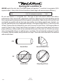
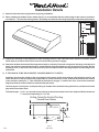
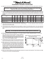
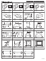
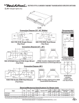
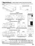
Read and Save These Instructions
All Hoods Must Be Installed By A Qualified Installer
INSTALLATION INSTRUCTIONS
SLH6-K UNDER CABINET HOOD
Read All Instructions Thoroughly Before Beginning Installation
WARNING - TO REDUCE THE RISK OF FIRE, ELECTRIC SHOCK,
OR INJURY TO PERSONS, OBSERVE THE FOLLOWING:
A. Installation work and electrical wiring must be done by qualified
person(s) in accordance with all applicable codes and standards,
including fire-rated construction. Switch power off at service panel
and lock the service disconnecting means to prevent power from
being switched on accidentally during installation.
B. When cutting or drilling into wall or ceiling, do not damage
electrical wiring and other hidden utilities.
C. Ducted fans must always be vented to the outdoors.
D. Sufficient air is needed for proper combustion and exhausting of
gases through the flue (chimney) of fuel burning equipment to
prevent back drafting. Follow the heating equipment
manufacturer’s guideline and safety standards such as those
published by the National Fire Protection Association (NFPA), and
the American Society for Heating, Refrigeration and Air
Conditioning Engineers (ASHRAE), and local code authorities.
WARNING - TO REDUCE THE RISK OF FIRE, USE ONLY METAL
DUCTWORK
L114A
Page 1
(Rev. 04/08)
C
UL
R
US
Ducting Do’s and Don’ts
NEVER restrict the duct size. The K250 blower unit requires 7” round duct or equivalent (32.5
square inches). Using Vent-A-Hood transitions (back page) will ensure proper efficiency.
Blower
K250
Duct Size
3 1/4” x 10” rectangular or equivalent
Sq. Inch Area
32.5”
Do not use flexible or corrugated duct. This type of duct will restrict airflow and reduce
performance. Only use smooth, galvanized, metal duct. Observe local codes regarding special
duct requirements and placement of duct against combustibles. Make the duct run as short and
as straight as possible with as few turns as possible. Avoid sharp-angled turns. Instead, use
smooth, gradual turns such as adjustable elbows or 45 degree angled turns. For duct runs over
20 feet, increase the duct diameter by one inch for every ten feet of duct. A 90 degree elbow is
equal to 5 feet of duct. Using Vent-A-Hood roof jacks or wall louvers (back page) will ensure
proper efficiency. Airflow must not be restricted at the end of the duct run. Do not use screen
wire or spring-loaded doors on wall louvers or roof jacks. Do not terminate venting into an attic
or chimney. Where possible, seal joints with duct tape. The hood must be ducted to the outdoors
without restrictions.
YES
Smooth Duct
Smooth Gradual Turn
Flexible Duct
Sharp Angled Turns
NO
L114A
Page 2
(Rev. 04/08)
Installation Details
1)
Read all instructions thoroughly before beginning installation.
2)
When installing the SLH6-K under cabinet hood, it is recommended that the bottom edge of the hood be located no
more than 21” - 24” from the cooking surface. Exceeding recommended mounting height may compromise performance.
Soffit
Cabinets
8’ Ceiling
6”
21”-24”
36”
3)
Inspect the underside of the cabinet for a flush mounting surface. If the underside of the cabinet is recessed, install
wood strips to provide a flush surface for the hood mounting screws to engage.
4)
Determine whether the hood will discharge horizontally or vertically. The hood is shipped to discharge vertically but is
easily converted to horizontal discharge by exchanging the discharge adapter on top of the hood (4 screws) with the
discharge cover on the back of the hood (2 screws). Use duct tape to seal the discharge adapter and discharge cover
to the hood.
5)
IF THE HOOD IS TO BE “BACK VENTED”, PROCEED DIRECTLY TO STEP 6.
Install the duct from the outside of the home down to the location of the hood exhaust outlet allowing room for the
VP521 transition on the top of the hood (if applicable). If a VP521 transition is used, install the duct down to the location
of the transition outlet plus 1”. This will allow the transition to engage 1” inside of the duct. Consult the connection
diagram (below) for further details on exhaust outlet placement.
Use duct tape to seal all joints. A complete listing of available Vent-A-Hood ducting materials is provided on the back
page of this instruction sheet.
Transition height: 3 1/4” x 10” duct will connect directly to the exhaust outlet of the hood. Optional VP521 transition to
7” round (sold separately) is 7 1/2” tall.
Ceiling Cutout for Vertical Ducting
Viewed from Above
7⁄8"
Back of Cabinet
2 5⁄8"
3 ½"
5 1⁄8"
5 1⁄8"
6 ¼"
CL
L114A
Page 3
(Rev. 04/08)
Electrical
Installation Details Continued
6)
Remove the hood from its packaging and place on the floor or countertop in front of the cabinet where it will hang.
Warning: Make sure power is off and locked at the service disconnecting
means on the service panel during installation.
7)
Determine whether the electrical wire will enter from the top or the back of the hood. Remove the electrical enclosure
cover (1 screw) and the top or back electrical enclosure knockout from the hood. Install an appropriate 1/2” UL listed
electrical wire clamp through the electrical knockout. Install electrical wiring from the electrical panel to the hood
location.
CFM
CFM
CFM
[email protected]” [email protected]” [email protected]”
Minimum Round
Duct Size
Square
Inches
200
7” (or equivalent)
38
155
7” (or equivalent)
38
195
180
7” (or equivalent)
38
160
145
7” (or equivalent)
38
Volts
Amps
RPM
CFM
[email protected]”
Equivalent CFM #
K250 (Top Vent - High)
115
3.2
1550
240
360
225
215
K250 (Top Vent - Low)
115
3.2
1200
170
255
170
160
K250 (Back Vent - High)
115
3.2
1550
220
330
215
K250 (Back Vent - Low)
115
3.2
1200
175
265
170
Model
All K-Series hoods have two halogen lights.
# Because the Magic Lung® uses centrifugal filtration rather than conventional baffle or mesh filters, the Magic Lung® blower can handle cooking equipment with higher cubic feet per minute (CFM) requirements and can deliver equivalent CFM much more efficiently
than other filtration systems. When comparing the Magic Lung® with other blower units made by other manufacturers, use the “Equivalent CFM”.
8)
Insert the electrical wire through the electrical wire clamp allowing 3” - 4” of wire inside the enclosure for hookup.
Tighten the electrical wire clamp.
9)
From inside the hood, using UL listed wire nuts, attach the “neutral” wire to the white lead, the “hot” wire to the black
lead, and the ground wire to the green lead inside the junction box. Replace the electrical cover previously removed in
Step 7.
Warning: Do not operate hood without proper ground connection.
10) FOR BACK VENTING APPLICATIONS ONLY. IF YOU ARE NOT BACK VENTING, PROCEED DIRECTLY TO STEP 12.
Note: Wall studs may interfere with back venting installations.
Additional framing may be required. It is necessary to cut a
duct access hole in the wall prior to installing the hood. Starting
2 1/8” above the bottom edge of the hood, cut a hole 3 1/2”
high x 10 1/4” wide (see diagram at right).
11) Install the duct from the outside of the home to the duct access
hole in the wall. Where possible, use duct tape to seal joints.
12) While aligning the duct and guiding the wires, position the
hood under the cabinet. The duct should connect together as
the hood is located in place. Note: Unless using the VP521
transition, the duct work must fit inside the exhaust collar. If
using the VP521, 7” round duct should be placed with the noncrimped end on the outside of the collar of the VP521 exhaust
outlet. Using the four screws provided, attach the hood to the
bottom of the cabinet.
Wall Cutout for Horizontal Ducting
Viewed from Front
3⁄8"
1 1⁄8"
Bottom of
Cabinet
3 ½"
Electrical
5 1⁄8"
5 1⁄8"
6 ¼"
CL
14) Refer to the Owner Maintenance Guide Operating Instructions for proper hood operation. Test all blower and light
functions to ensure they are operating properly.
L114A
Page 4
(Rev. 04/08)
VENTING A
CCESSORIES
ACCESSORIES
WALL LOUVER
WALL LOUVER
8 5⁄8”
WALL LOUVER
13”
11”
Back
View
6”
7”
8”
RECTANGULAR WALL LOUVER
Back
View
11”
8 ½”
13”
1 ½” Flange
1 ½” Flange
10”
Back
View
3 ¼”
6”
E
ANG
2” FL
E
NG
1 ½” Flange
A
” FL
1½
MODEL
DIM
MODEL
DIM
MODEL
DIM
MODEL
DIM
VP526
VP527
VP528
6” Round
7” Round
8” Round
VP554
10” Round
VP555
12” Round
VP538
VP560
6” x 8 ½“
3 ¼” x 10”
LOW PROFILE ROOF JACK
(MAXIMUM 4/12 PITCH)
LOW PROFILE ROOF JACK
(MAXIMUM 4/12 PITCH)
ADJUSTABLE ELBOW
BACK/SIDE VENT ELBOW
12”
16 ¾”
6 ½”
VP513 - 8 ½”
VP514 - 9 9⁄16”
VP515 - 10 5⁄8”
10 ½”
22 ½”
16 ¾”
8 ½”
6”
7”
8”
6”
16”
20 ¾”
8” Round
MODEL
DIM
MODEL
DIM
MODEL
DIM
MODEL
DIM
VP539
VP540
VP541
6” Round
7” Round
8” Round
VP552
VP553
10” Round
12” Round
VP513
VP514
VP515
6” Round
7” Round
8” Round
VP561
8” to 6” x 8 ½”
3 ¼” x 10” BACK VENT ELBOW
“Y” TRANSITION
MULTI-BLOWER TRANSITION
10”
12”
14”
3 ¼” x 10” TO 7” TRANSITION
10”
12”
7”
3 ¼”
VP562 - 17 ½”
VP563 - 16 ½”
4 ¼”
7 ½”
18”
10”
3 ¼”
VP562 - 23 ¼”
VP563 - 30 ½”
10”
3 ¼”
MODEL
DIM
MODEL
DIM
MODEL
DIM
MODEL
DIM
VP559
3 ¼” x 10”
VP562
VP563
6” & 8” to 10”
8” & 8” to 12”
VP517
VP518
VP551
8” & 8” to 12”
6” & 8” to 12”
6” & 8” to 10”
VP521
3 ¼” x 10” to 7”
OFFSET KIT - RECTANGULAR
OFFSET KIT - ROUND
3 ¼”
7”
10 ½”
11”
STANDARD ISLAND TRANSITION
CLUSTER BLOWER TRANSITION
12”
8”
10”
9”
11”
11”
11 ¼”
6”
16”
6”
16”
16”
5”
18 ½”
MODEL
DIM
MODEL
DIM
MODEL
DIM
MODEL
DIM
VP529
6” Rnd to 7” Rnd
VP550
6” Rnd to 3 ¼” x 10”
VP565
5” x 16” to 8”
VP564
8” & 8” to 12”
OFFSET L & R TRANSITION
FOR ISLAND BLOWERS
SIDE VENT TRANSITION L & R
FOR ISLAND BLOWERS
8”
6” x 8 ½” COLLAR
6” & 8” COLLAR
19”
2” Larger
Than Cutout
8”
6” Dia.
8” Dia.
6” x 8 ½”
Opening
9”
12”
16”
16”
5”
2” Larger
Than Cutout
5”
DIM
MODEL
DIM
MODEL
DIM
MODEL
DIM
VP542
VP543
Top Left
Top Right
VP544
VP545
Left Side
Right Side
VP533
VP535
6” Round
8” Round
VP537
6” x 8 ½”
ROUND DUCT PIPE
3 ¼” RECTANGULAR DUCT PIPE
6”
7”
8”
3 ¼”
36”
6” RECTANGULAR DUCT PIPE
6”
10”
12”
16”
30”
L114A
11 ½”
MODEL
8½
24”
MODEL
DIM
MODEL
DIM
MODEL
DIM
VP500
VP501
VP502
6” Round
7” Round
8” Round
VP504
VP505
VP506
3 ¼” x 10”
3 ¼” x 12”
3 ¼” x 16”
VP507
6” x 8 ½”
Page 5
”
Rev. 04/08