1
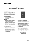
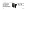
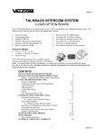
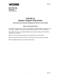
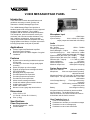
Issue 6
V-9908 MESSAGE/PAGE PANEL
Introduction
These instructions contain the specifications and
guidelines necessary to install, operate, and
maintain the V-9908, Message/Page Panel.
The V-9908 Message/Page Panel provides a
handheld push-to-talk microphone for live pages and
storage for eight messages. The V-9908 is
compatible with all Valcom self-amplified speakers.
The microphone, power and internal memory are
monitored, with visual and audible indicators if any
fault conditions are detected. When used with
Valcom Supervised Distributed Amplified One-Way
Paging Speakers and Horns, full system supervision
including the speaker audio path is possible.
Microphone Input
Input Impedance:
>5000 Ohms
Input sensitivity:
1kHz 1 millivolt for -12dBm
output (output terminated with 100 Ohms)
Audio
Frequency Response:
Mic – Output:
150Hz – 7,000Hz
Frequency Response:
Stored Messages – Output:
150Hz – 3,500Hz
Input Sensitivity (mic):
1kHz 1 millivolt for -12dBm
output (output terminated with 100 Ohms)
Signal to Noise (Idle mode, Ref -12dBm):
>70dB
Signal to Noise (Mic active, Ref -12dBm)
>50dB
Distortion (Mic – Output):
< 1% THD at -12dBm
Output Impedance:
< 25 Ohms
Nominal output level:
-12dBm (Ref 600 Ohms)
Maximum output level:
0dBm (before clipping)
Applications
Valcom Supervised Distributed Amplified
One-Way Paging Systems.
Refer to Figure 1 for a block diagram of a typical
installation.
Features
Dynamic noise canceling handheld microphone
for live page
Provides up to 8 minutes of high quality digital
recording
Stores and plays up to 8 messages
Eight (8) preprogrammed messages included
PC Programmable
Message panel fully supervised
Provides speaker line supervision
Provides microphone supervision
Provides DC power supervision
Allows remote message activation
Visual and audible system trouble indication
Audible signal cancel button
Power "ON" indicator
Mounts in most 4 gang deep electrical box
System Supervision
Main Audio Channel:
30Hz tone (inaudible)
Microphone:
1kHz tone supervises the preamp,
cable and element
Microphone Switch: DC loop with 4.7K Ohm resistor
Audio Output: DC loop terminated with a 4.7K Ohm
1/4W resistor
Voice Storage Memory:
Fixed segment memory
monitoring
Main Power:
9VDC battery provides redundant
supervision power
Battery:
Low voltage monitoring
All system faults are indicated by both an audible
and visual alarm. The audible alarm may be
silenced, however, the visual indicator will continue
to illuminate until the fault is removed.
Dimensions
5"W x 4.25"H x 2”D
(12.7cm W x 10.8cm D x 5.08cm H)
4 lbs. (1.5Kg)
User Controls (Figure 1)
Specifications
Push-to-Talk Microphone
Pushbuttons to activate pre-recorded messages
Pushbutton to cancel message play
Pushbutton to cancel wire fault alarm
Power Requirements
Operating Voltage 22 – 26VDC
Current 250mA
1
947980
The final format is standard 8 bit uLaw at 8kHz
compressed format.
Indicators (Figure 1)
Power “ON”
Individual message play
Visual system fault
Audible system fault with silence button
Although it is possible to upload and download
during system operation, it is recommended to
perform this function when the system is not in use.
This insures that messages will not be corrupted
during a download or upload. After message write
remove battery and DC power momentarily.
Total voice message storage is 8 minutes and there
are no other restrictions on lengths of individual
messages. It is possible to record tones, signals,
etc. that will operate in the voice band range. For
additional programming information refer to the
Message Control Panel Program Tool Help Menu.
Inputs (Figure 2)
Eight remote message activation inputs via
single pole pushbutton switches.
RS-232 provided for message uploads and
downloads.
Handheld microphone for “live” announcements
Outputs (Figure 2)
Audio output
Page/Message active contact
External contact closure activates on system
fault.
System Fault Monitoring
The main audio channel has an inaudible tone
present whenever a page or message is not active.
This tone will verify the integrity of the audio channel
from the microphone to the audio output. A Valcom
V-1096 Audio Interface (included) is required when
the speaker runs are non-supervised.
System Operation
The Push-to-Talk microphone is used for live pages.
The microphone has priority over message playback
paging. Pressing the Push-to-Talk switch on the
microphone will activate the audio output and
override (and CANCEL) any message playback in
process.
Proper operation of the voice memory flash device is
monitored by continuous reading a fixed segment of
the memory. This insures the flash memory integrity
as well as the circuitry that attaches it to the DSP
controller. It will detect defective components and
interconnection faults as well as actual memory
failure.
A group of eight (8) front panel buttons with
associated LED’s are used to activate stored
messages. When a message is activated, the LED
will indicate the status. If the message is playing,
the LED will illuminate. Messages are not
chainable. A message must be finished before an
additional message may be activated. If a message
button is pressed while a message is playing the
original message will cancel.
In the event of a system or power failure, the
“System Fault LED” will illuminate and an audible
alarm will sound. The Audible alarm may be
silenced by pressing the “Cancel Audible” button,
however the “System Fault” LED will remain lit until
the fault has been corrected. A 9 Volt battery
located on the back of the Page Panel provides the
necessary power to operate the fault circuits in the
event of a power failure. The 9 Volt battery is
monitored and a system fault will occur when the
battery voltage drops. A contact closure is available
to signal a remote monitoring panel when a system
fault occurs.
A “MESSAGE CANCEL” button is available to
cancel any message playing.
Using the program tool, all messages can be
programmed for the following play scenarios:
1 play per button activation
2 plays per button activation
3 plays per button activation
Continuous plays per activation (cancelled via
“MESSAGE CANCEL” button)
Full System Supervision using Valcom One-Way
Supervised Self-Amplified Speakers and Horns with
the Page Panel includes monitoring of the audio and
power pairs to the speakers for shorts, opens and
grounds. A fault detected on these lines will cause
the “System Fault” LED to illuminate. A Valcom
V-9999 End of Line device (not included) is required
for speaker line termination.
Programming Voice Messages
Eight (8) preprogrammed messages are provided in
the V-9908. (See Table 1, for script of
preprogrammed messages).
Installation
A serial port (RS-232) is provided to upload and
download voice messages. The program tool
provides all editing and message processing (AGC,
response shaping, wave file conversions, etc.).
Refer to the figure on the following pages for wiring
connections. All connections should be made to the
Message Panel and double-checked prior to
connecting DC power.
2
947980
Figure 1 shows microphone, message activate
and fault indication control locations.
System Troubleshooting
There are 4 LED’s located on the PC board for
system troubleshooting. They are:
LED D9 - Mic. Switch Fault
(ON = fault detected)
LED D10 - DC Fault (low battery or
internal monitoring System fault)
(ON = fault detected)
LED D11 - Audio loop back fault
(ON = Fault in Mic. audio or 30Hz
amplifier loop back)
LED D12 - Flash Memory Error
(ON = Checksum failed)
Figure 2 shows remote message activate terminal
connections, output connections, programming
and power connections located on the back of the
message panel.
Figure 3 shows a typical connecting arrangement
and other feature connections for a Fully
Supervised system, including speaker wire run
supervision. Fully supervised systems require a
Valcom V-9999 End of Line terminator (not
included). Refer to Figure 3 to connect the
message active contact and remote activation of
the messages. Using a RJ-45 connector, connect
speaker audio (Tip and Ring) and speaker power
to board mounted connector as shown on
connecting diagram. (A remote mounted
connecting block will be required to access these
connections.) Referring to Figure 3, connect
24VDC as indicated.
TECHNICAL ASSISTANCE
When trouble is reported, verify the unit is
turned on and there are no broken
connections leading to the unit.
Assistance in troubleshooting is available from
the factory. When calling, you should have a
VOM and a test set and call from the job site.
Call (540) 563-2000 and press 1 for Technical
Support, or visit our website at
http://www.valcom.com.
When installed without full wire run supervision, a
Valcom V-1096 Audio Interface is required to be
installed inline on the audio output between the
V-9908 Message Panel and the first connected
device (page control or speaker – refer to page 5
for details)
Valcom equipment is not field repairable.
Valcom maintains service facilities in
Roanoke, VA. Should repairs be necessary,
attach a tag to the unit clearly stating company
name, address, phone number, contact
person, and the nature of the problem.
Send the unit to:
Valcom, Inc.
Repair and Return Dept.
5614 Hollins Road
Roanoke, VA 24019-5056
Programming the Message Panel
Refer to the programming guide included with the
message panel documentation.
VALCOM LIMITED WARRANTY
Valcom, Inc. warrants its products only to the original purchaser, for its own use, to be free from defects in materials and workmanship under
conditions of normal use and service for a period of one year from the date of shipment. This Limited Warranty obligation shall be limited to the
replacement, repair or refund of any such defective device within the warranty period, provided that:
1. inspection by Valcom, Inc. indicates the validity of the claim;
2. the defect is not the result of damage, misuse or negligence after the original shipment;
3. the product has not been altered in any way or repaired by others and that factory sealed units are unopened (a service charge plus parts
and labor will be applied to units defaced or physically damaged);
4. freight charges for the return of products to Valcom are prepaid;
5. all units 'out of warranty' are subject to a service charge. The service charge will cover minor repairs (major repairs will be subject to
additional charges for parts and labor).
This Limited Warranty is in lieu of and excludes all other warranties, expressed or implied and in no event shall Valcom, Inc. be liable
for any anticipated profits, consequential damages, loss of time or other losses incurred by the buyer in connection with the purchase,
operation, maintenance, installation, removal or use of the product. The maximum liability of Valcom under this warranty is limited to
the purchase price of the specific Product covered by the warranty.
Disclaimer. Except for the Limited Warranty provided herein, the product is provided “as-is” without any warranty of any kind whatsoever
including, without limitation, any WARRANTY OF MERCHANTABILITY, FITNESS FOR A PARTICULAR PURPOSE OR NON-INFRINGEMENT.
This warranty specifically excludes damage incurred in shipment. In the event a product is received in damaged condition, the carrier should be
notified immediately. Claims for such damage should be filed with the carrier involved in accordance with the F.O.B. point.
Headquarters:
Valcom, Inc.
5614 Hollins Road Roanoke, VA 24019-5056
Phone: (540) 563-2000 FAX: (540) 362-9800
3
947980
Noise Canceling Handheld
Push to Talk Microphone
Message Cancel
Button
Eight (8) Message
Play Buttons
Eight (8) Message
Play Indicators
Message Label
Window
Fault Audible
Cancel Button
Figure 1: User Control Locations
System Fault
Indicator
Message Activate
Contact Closure Inputs
Serial Programming
Input
9 V Alkaline
Battery
Output
Connections
RJ-45 Connection Detail
Audio Output Pair
CONTACT CLOSURE PAIR
PIN 1
Message Play Contact Pair
-24VDC Output 2APair
24VDC Input
Power Connection
PIN 8
Figure 2: Rear Connections
RJ45 Pin Assignment
Pin 1 Audio Out
Pin 2 Audio Out
Pin 3 Supervision 4.7K resistor (A “no fault” condition results in 4.7K ohm between pins 3 and 6)
Pin 4 Message Play Contact (Pins 4 and 5 short when audio is present on pins 1 and 2)
Pin 5 Message Play Contact
Pin 6 Supervision 4.7K resistor
Pin 7 24VDC
Pin 8 24VDC Common
Figure 2: Rear Connections
4
947980
Remote Activation
Single Pole Switch
Valcom Amplified
Supervised Speakers
Message 1
Message 2
Message 3
Message 4
Message 5
Message 6
Message 7
Laptop computer
Message 8
Ground
RS 232
Program Port
Cancel Message
Remote Message Play Inputs
Connect field wiring
directly to speaker
terminals or speaker
pigtails.
Tip
Ring
Gnd
-24vdc
Tip
Ring
Gnd
-24vdc
COM
- 24VDC
9 Volt Alkaline
Battery
V-9999
EOL
Terminator
not included
Figure 3: Typical Connections - Fully Supervised System
Shorting
Jumper
Position
1
2
3
AUDIO
OUTPUT
CONTACT
CLOSURE
AUDIO
INPUT
V-1096
AUDIO ADAPTER
Shorting
Jumper
Position
1
2
3
1
Shorting
Jumper
Position
2
3
Default shorting jumper
positions are shown.
(from top to bottom –
up, up, down).
The only time that these
need to be moved is
when connecting the
output of the V-1096 to
a lo-z microphone input.
In this case, all of the
jumpers must be moved.
(From top to bottom down, down, up)
When the V-9908 is not being used as shown in Figure 3, a V-1096 Audio Adapter must be
utilized.
1) Connect the audio output of the V-9908 to the audio input of the V-1096.
2) Connect the audio output of the V-1096 to the audio input of the receiving system.
Examples of receiving systems include a tip/ring telephone input on a Valcom Page
Control, the tip/ring audio input of one or more Valcom Self Amplified Speakers, a line
level music or auxiliary input on a Valcom page control, IP Audio gateway or amplifier, or
a lo-z microphone input. In the case of a lo-z microphone input, such as that found on
Valcom MultiPath or Class Connection systems, all of the shorting jumpers must be
moved from the default positions shown above.
3) If the audio input of the receiving system requires a “loop start” connection, then connect
the message play contacts of the V-9908 to the Contact Closure input of the V-1096.
4) If the audio input of the receiving system requires an activation closure, then connect the
message play contacts of the V-9908 to the activation input of the receiving system.
5
947980
Preprogrammed Messages included in the V-9908
*In order to personalize these messages, please refer to content found on
the CD included with the V-9908.
Message 1:
(Triple buzz, repeated three times) “May I have your attention, please. A fire
emergency has been reported in the building. While this is being verified,
please leave the building by the nearest exit or exit stairway. Do not use the
elevators”.
Message 2:
(Triple buzz, repeated three times) “May I have your attention, please. An
emergency has been reported in the building. While this is being verified,
please leave the building and report to the designated assembly area for your
group”.
Message 3:
May I have your attention, please. “The National Weather Service has issued a
Severe Weather Warning for our area”.
Message 4:
(Triple buzz, repeated three times) “May I have your attention, please. A fire
emergency has been reported in the building. While this is being verified,
please leave the building by the nearest exit”.
Message 5:
(Whoop tone twice) “May I have your attention, please. An emergency has
been reported in the building. While this is being verified, please, stand by for
further instructions”.
Message 6:
(Chime three times) “May I have your attention, please. The building
emergency has ended; an all clear has been given. Please resume normal
activities”.
Message 7:
“This is a test of the building public announcement system. This system is
designed to provide up to the minute communications to the workforce during
emergencies. In an Emergency a professional security force will provide real
time verbal exit instructions to specific zones within the complex, or to the
entire complex from the central alarm station in the security office. This is a
test”.
Message 8:
(Train Whistle)
Table 1
6
947980