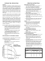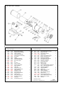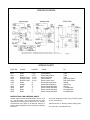
1
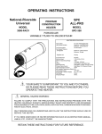
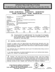
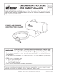
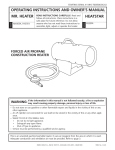
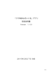
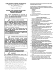
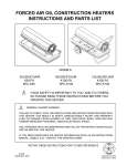
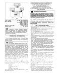
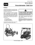
OPERATING INSTRUCTIONS
National-Riverside
Universal80-FAP
HEATERMODEL
MODELS 150-FAST
SPC
ALL-PRO
MODEL SPC-150T
PROPANE
CONSTRUCTION
HEATER
FORCED AIR
150,000 BTU/HR
HEATER SPECIFICATIONS - 150
Type of Gas
Input Rating
Fuel Consumption
Gas Supply Pressure
to Regulator
Regulator Out
Fuel Orifice Size
Electrical Input
Minimum Operating Voltage
Fan
Average Air Temp Rise
Ignition
Primary Flame Control
High Temperature Limit Control
Minimum Ambient Temp. Rating
Size (Length x Width x Height)
New Weight
Shipping Weight
!
!
For Use with Propane Gas Only
150,000 BTU/hr
7 Lbs/hr
Max: Bottle Pressure
Min: 5 psig
11" W.C.
1.00 mm Drill - 18 Holes
115V, 60Hz 10, 4a
100V
3000 rpm, 450 cfm
Approx. 300oF
Direct Spark, Interrupted Type
Solid State, 10-15 second Timing
240oF
0oF
26" x 9" x 16"
32 lbs.
34 lbs.
YOUR SAFETY IS IMPORTANT TO YOU AND TO OTHERS,
SO PLEASE READ THESE INSTRUCTIONS BEFORE YOU
OPERATE THIS HEATER.
GENERAL HAZARD WARNING:
FAILURE TO COMPLY WITH THE PRECAUTIONS AND INSTRUCTIONS PROVIDED WITH THIS
HEATER, CAN RESULT IN DEATH, SERIOUS BODILY INJURY AND PROPERTY LOSS OR DAMAGE
FROM HAZARDS OF FIRE, EXPLOSION, BURN, ASPHYXIATION, CARBON MONOXIDE POISONING,
AND/OR ELECTRICAL SHOCK.
ONLY PERSONS WHO CAN UNDERSTAND AND FOLLOW THE INSTRUCTIONS SHOULD USE OR
SERVICE THIS HEATER.
IF YOU NEED ASSISTANCE OR HEATER INFORMATION SUCH AS AN INSTRUCTIONS MANUAL,
LABELS, ETC. CONTACT THE MANUFACTURER.
RETAIN THESE INSTRUCTIONS FOR FUTURE REFERENCE.
OPERATING PRECAUTIONS
SAFETY PRECAUTIONS
This is a propane, direct-fired, forced air heater. It's intended
use is primarily temporary heating of buildings under construction, alteration or repair.
1.
!
WARNING
NOT FOR HOME OR RECREATIONAL VEHICLE USE
3.
4.
Propane is heavier than air. If propane leaks from a connection
or fitting, it sinks to the floor, collecting there with the surrounding air, forming a potentially explosive mixture. Obviously,
propane leaks should be avoided, so set up the propane supply
with utmost care. Leak check new connections or reconnections
with a soap and water solution and follow all connection
instructions herein. Also, ask your propane dealer for advice
on the propane supply installation and ask him to check it if
there are any questions.
5.
Direct-Fired means that all of the combustion products enter
the heated space. Even though this heater operates very
close to 100 percent combustion efficiecy, it still produces
small amounts of carbon monoxide. Carbon monoxide (called
CO) is toxic. We can tolerate small amounts but not a lot. CO
can build up in a heated space and failure to provide adequate
ventilation could result in death. The symptoms of inadequate
ventilation are:
headache
dizziness
burning eyes and nose
nausea
dry mouth or sore throat
So, be sure to follow advice about ventilation in these operating
instructions.
8.
Forced Air means that a blower or fan pushes the air through
the heater. Proper combustion depends upon this air flow;
therefore, the heater must not be revised, modified or operated with parts removed or missing. Likewise, safety systems
must not be circumvented or modified in order to operate the
heater.
When the heater is to be operated in the presence of other
people the user is responsible for properly acquainting
those present with the safety precautions and instructions, and of the hazards involved.
2.
6.
7.
9.
10.
11.
12.
13.
14.
15.
16.
17.
Check the heater thoroughly for damage. DO NOT
operate a damaged heater.
DO NOT modify the heater or operate a heater which
has been modified from its original condition.
Use only propane gas.
Use only VAPOR WITHDRAWAL propane supply. If
there is any question about vapor withdrawal, ask
your propane dealer.
Mount the propane cylinders vertically (shutoff valve
up). Secure them from falling or being knocked over
and protect them from damage.
Locate propane containers at least 7 ft. from the
heater and do not direct exhaust toward containers.
Use only the hose and regulator assembly provided
with the heater. Inspect hose assembly before each
use of the heater. If there is excessive abrasion or
wear, or hose is cut, replace with hose assembly
listed on parts list before using heater.
For indoor use only. Area must be well ventilated.
Provide minimum openings of 2 sq. ft. near the floor
and 2 sq. ft. near the ceiling (also see "Operating
Precautions").
If at any time gas odor is detected, IMMEDIATELY
DISCONTINUE operation until the source of gas has
been located and corrected.
Install the heater such that it is not directly exposed to
water spray, rain and/or dripping water.
Maintain minimum clearance from normal combustible material (like paper) as follows:
floor-0 ft.;outlet-6 ft.; sides-1 ft.; top-3 ft. Locate 10 ft.
from canvas or plastic tarpaulins or similar coverings
and secure them to prevent flapping or movement
due to wind action.
Operate only on a stable, level surface.
Do not use with ductwork. Do not restrict inlet or exit.
Use only the electrical power specified. The electrical connection and grounding must comply with
National Electrical Code - ANSI/NFPA 70.
Use only a properly grounded 3-prong receptacle or
extension cord.
Do not move, handle or service while hot or burning.
Use only in accordance with local codes or, in the
absence of local codes, with the Standard for the
Storage and Handling of Liquefied Petroleum Gases
ANSI/NFPA 58-1998.
WARNING: FIRE, BURN, INHALATION, AND EXPLOSION HAZARD. KEEP SOLID COMBUSTIBLES, SUCH
AS BUILDING MATERIALS, PAPER OR CARDBOARD, A
SAFE DISTANCE AWAY FROM THE HEATER AS RECOMMENDED BY THE INSTUCTIONS NEVER USE THE HEATER
IN SPACES WHICH DO OR MAY CONTAIN VOLATILE OR
AIRBORNE COMBUSTIBLES, OR PRODUCTS SUCH AS
GASOLINE, SOLVENTS, PAINT THINNER, DUST PARTICLES OR UNKNOWN CHEMICALS.
Page 2
OPERATING INSTRUCTIONS
PROPANE FUEL PRECAUTIONS
WARNING:
Local codes for installation of propane systems may vary
considerably. Therefore, ask your local propane supplier for
advice on propane system installation in your particular area.
In the absence of local codes, install in accordance with
American National Standards Institute (ANSI)/National Fire
Protection Association (NFPA) publication Standard for the
Storage and Handling of Liquefied Petroleum Gases ANSI/
NFPA 58-1998. Your supplier, fire marshal or library should
have a copy.
The propane supply system must be arranged for vapor
withdrawal. Propane cylinders must be secured in the upright
position to keep them from falling or being knocked over.
During use, liquid propane in a container vaporizes. As it
vaporizes, the propane cools itself. If this cooling process
continues long enough and proceeds fast enough, the propane temperature and pressure will fall so low that heater
operation may be improper or even impossible even though
plenty of propane remains in the container. Often frost forms
on the outside of the propane container as a warning of
excessive refrigeration.
Recommendations to reduce the ill effects of refrigeration are:
* Provide considerably more propane than you plan to
consume. As a rule of thumb, provide twice as much.
* Fill containers frequently, especially in cold weather.
Never allow propane to fall below one-third of container capacity.
* If possible, keep containers in a warm area. Under
no circumstances should the heater exhaust be
directed toward the propane container.
* Watch for frost formation on the container. If it
occurs, discontinue use of the heater and refill the
container.
SIZE AND CAPACITY OF PROPANE CYLINDERS
The chart below shows the approximate size of the cylinder
required for this heater. To use the chart:
1. Select the lowest air temperature expected (at the
bottom of the chart).
2. Move straight up to time of operation desired (left
side of chart).
3. Read the cylinder size required.
PREPARING FOR OPERATION
1. Check the heater for possible shipping damage. If
any is found, immediately notify your dealer.
2. Follow all of the "Precautions" on pages 2 & 3.
3. Connect the POL fitting of hose and regulator assembly to the propane cylinder by rotating the POL nut
counterclockwise into the propane cylinder's valve
outlet and securely tighten with a wrench.
4. Connect the hose to the heater by rotating the hose
fitting clockwise.
5. Securely tighten all gas connections.
6. Open the cylinder's gas valve and check all gas
connections with a soap and water solution. DO NOT
USE A FLAME.
7. Connect power cord to well-grounded 115V, 60 Hz, 10
source of power.
8. When using an extension cord, make certain that it is
a 3-wire (grounded) cord of proper wire size. See
chart on page 4.
START
1. Slowly open the main valve at propane cylinder.
2. Set the thermostat to the desired temperature.
Heater will turn on and off automatically as the
temperature varies in the heated areas.
STOP
1. Securely close valve on the propane cylinder.
2. Continue to operate heater until all fuel in the hose
has burned.
3. Turn the heater thermostat to off.
RESTART AFTER SAFETY SHUTDOWN
1. Securely close valve at propane cylinder. Unplug
heater.
2. Wait 5 minutes.
3. Restart following "Start" procedure.
MAINTENANCE AND STORAGE
1. The heater should be inspected before each use, and
at least annually by a qualified person.
2. Before each use, check the soft "O" ring seat at the
bullnose of the POL fitting. If the "O" ring is cut,
scuffed, or otherwise damaged, replace it with part
number 6681.
3. Turn off the gas at the LP-gas supply cylinder(s) when
the heater is not in use.
4. When the heater is to be stored indoors, the connection between the LP-gas supply cylinder(s) and the
heater must be disconnected and the cylinder(s)
removed from the heater and stored out of doors and
in accordance with Chapter 5 of the standard for
Storage and Handling of Liquefied Petroleum Gases
ANSI/NFPA 58-1998.
Recommended Minimum Gauge for Cord Extensions
Wire Gauge Chart A.W.G.
Name
Plate 120V
Amps.
25
5-6
6-8
8-12
10-12
12-14
18
18
18
16
16
Cord Length in Feet
50
100
150
16
16
14
14
12
14
12
12
10
10
12
10
10
8
8
150-FAST/SPC-150FAST
Item
Part No.
Description
Qty
Item
150-FAST SPC-150FAST
1
2
3
4
5
6
7
8
9
10
11
12
13
14
15
16
17
18
19
20
21
22
23
24
25
26
27
1700
1672
1168
1146
1550
3038
7095
7094
1939
6010
6074
6041
6030
3133
1561
3087
6225
3132
6152
6255
6433
6122
6100
6123
1171
1083
3037
1712
1672
1168
1146
1550
3038
7095
7094
1940
6010
6074
6041
6030
3133
1561
3087
6225
3132
6152
6255
6433
6122
6100
6123
1171
1083
3037
Part No.
Description
Qty.
150-FAST SPC-150FAST
Burner Shell Assembly
Middle Cylinder Assembly
Orifice Assembly
Flame Holder Assembly
High Limit Control Assembly
Nut, Orifice
Handle
Handle Mounting Clip
Motor Shell Assembly
Set Screw, Nyloc
Fan
Nut, Lock
Screw, Machine
Support, Motor Strap
Motor Assembly
Grille, Inlet
Snap Bushing, 5/8
Saddle, Motor Support
Hose Assembly
Regulator, 11" WC
POL Excess Flow
Fitting, Male Connector
Solenoid Valve
Fitting, Male Connector
Fuel Tube Assembly
Spark Plug
Nut, Spark Plug 14 mm
1
1
1
1
1
1
1
2
1
1
1
1
1
2
1
1
1
1
1
1
1
1
1
1
1
3
28
29
30
31
32
33
34
35
36
*
**
**
*
*
1
*
*
*
*
*
*
**
**
**
**
*
3441
6070
1734
10739
3333
6223
1036
1942
1937
6189
7219
3210
6712
7744
*
7789
7067
6383
7743
6410
7745
7499
10739
6641
3983
1959
3441
6070
1734
10739
3333
6223
1036
1942
1937
6189
7219
3210
6712
7744
6374
7789
7067
6752
7743
6410
7745
7499
10739
6641
3983
1959
Thermostat Mounting Bracket
Clamp Loop, 5/16
Thermostat Assembly
Flame Control
1
Flame Control Bracket (7499)
Bushing, Strain Relief, 1/4
Power Cord Assembly
Thermostat Knob Assembly
Control Box Assembly
Terminal, "Y" Adaptor
Control (Mark 10N)
Bracket (7219)
Label, Hangtag
Label, Model/Operating Instructions
6374 Label, Electrical Ground
Label, Wiring Diagram
Label, BTU Rating
Label, Logo
Manual, Operating Instr.
Label, Thermostat
Parts List/Wiring Diagram
Flame Control
Flame Control Mini Potted
Terminal Board (7801 & 7808)
Bracket (7801 & 7808)
Harness
** Alternate Control
*Not shown on exploded view
1
1
1
1
1
1
1
1
2
1
1
1
1
1
1
2
2
1
1
1
1
1
1
1
1
7745B
SEPTEMBER 2001
WIRING DIAGRAM
WIRING CHART
PART NO.
COLOR
LENGTH
1041
1041
1226
1226
1226
1188
1111
1959
1959
1959
1959
White
White
Red (Hi-Temp)
Red (Hi-Temp)
Red (Hi-Temp)
Green
Orange
Green
Red
White
Black
4 1/2"
4 1/2"
16 1/2"
16 1/2"
16 1/2"
6"
8"
7"
7"
6"
6"
FROM
TO
Terminal Block
Flame Control Valve
High Limit Switch
Terminal Block
Flame Control Valve
Flame Control (Ground)
Flame Control (Ignition)
Flame Control (Harness)
Flame Control (Harness)
Flame Control (Harness)
Flame Control (Harness)
Valve
Valve
Valve
High Limit Switch
High Limit Switch
Ground
Spark Plug
Ground
Terminal Block
Terminal Block
Terminal Block
INSTRUCTIONS FOR ORDERING PARTS
All parts orders must show heater Model No., Item No., Part
No., and Description. We recommend that only parts
supplied by the manufacturer be used on this unit. A locally
purchased part may appear to be identical, although in
reality it might endanger the heater or the persons operating
the heater.
The heater should be serviced only by a trained, experienced service person.
Read the section on "Servicing" before ordering parts.
For parts order, call (909) 981-5343.
150-FAST/SPC-150T
SERVICING
A hazardous condition may result if a heater is used that
has been modified or is not functioning properly. When the
heater is working properly:
* The flame is contained within the heater.
* The flame is essentially blue with perhaps
some yellow tipping.
* There is no strong disagreeable odor, eye
burning or other physical discomfort.
* There is no smoke or soot internal or external to
the heater.
* There are no unplanned or unexplained shut
downs of the heater.
The parts lists and wiring diagram show the heater as it was
constructed. Do not use a heater which is different from
that shown. In this regard, use only the hose, regulator and
cylinder connection fitting (called a POL fitting) supplied
with the heater. Do not use alternates. For this heater, the
regulator must be set to supply 11" water column (W.C.)
outlet pressure (.40 psig). If there is any uncertainty about
the regulator setting, have it checked.
A heater which is not working right must be repaired, but
only by a trained, experienced service person. Contact the
factory for the service center closest to you, phone number
(909) 981-5343.
You may also obtain in-warranty or out-of-warranty service
by returning the product freight prepaid to:
Scheu Products Company
8855 Baker Avenue
Rancho Cucamonga, CA 91730
TECHNICAL INFORMATION
HOW MUCH HEAT DO I REQUIRE?
For economy, it is important to match input to that
required. But heat requirements often vary. For example, it usually takes a lot more heat to get things warm
than it does to keep them that way. Likewise, outside air
temperature usually changes during the day so you may
need more heat at night than you do in the daytime. An
approximation of the heat required can be found by using
the chart below.
BTU'S PER HOUR REQUIRED
Cubic feet
of space to
be heated
Temperature Rise Required (oF)*
20o
30o
40o
50o
5,000
14,000
20,000
27,999
34,000
7,000
19,000
28,000
38,000
47,000
10,000
27,000
40,000
54,000
67,000
15,000
40,000
60,000
80,000
100,000
20,000
54,000
80,000
107,000
133,000
30.000
80,000
120,000
160,000
200,000
50,000
133,000
200,000
266,000
333,000
WARNING: When using a thermostat the heater exit
area should be protected from personnel and warnings
posted of sudden startup.
In-warranty products returned to the Service Department
will be repaired with no charge for either parts or labor and
will be returned to you freight prepaid. Please include a
brief statement indicating date, place of purchase, the
nature of the problem and proof of purchase.
Out-of-warrranty products returned to the Service Department will be repaired with a charge for parts and labor and
will be returned to you freight collect.
ANSI Z83.7b-1993/CGA 2.14-1972
Construction Heater
Page 4
SCHEU PRODUCTS COMPANY, INCORPORATED
MAIL: P.O. BOX 250, UPLAND, CA 91785
PLANT: 8855 BAKER AVE., RANCHO CUCAMONGA, CA 91730
TELEPHONE: 909-981-5343
P/N 7743D
September 2000