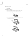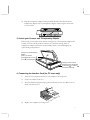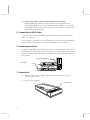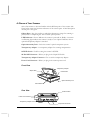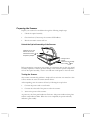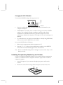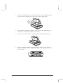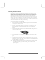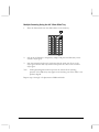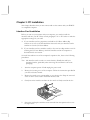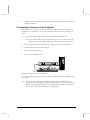
1
UMAX Mirage II
Color Scanner
Operation Manual
Thank you for purchasing the color scanner. With the color scanner, you can easily scan
A3 size documents and photographs into your computer and maintain them as electronic
copies.
Main Features:
•
High Resolution and Density Range: High resolution and density range define a high-end flatbed scanner. Your
scanner offers an ultra high maximum resolution of 9800 dpi, producing better gamma transformation, and a
more accurate detection of highlight and shadow details, thereby allowing even distribution of colors.
•
Power Twin Lens: Your scanner offers a dual-lens feature that enables users to choose between two optical
resolutions: 700 x 1400 dpi and 1400 x 2800 dpi. It is like having two scanners in one machine. The extended
optical resolution is extremely helpful when scanning small images, such as 35mm slides.
•
High Scanning Speed, Low Acoustic Noise: Your scanner can complete a color preview in a few seconds. In fact,
when compared to drum scanners, your scanner has proved to be five times faster in color scan speed tests.
The scanner's micro stepping technology greatly increases scanning speed and at the same time reduces noise
level.
•
Transparency Adapter: It allows the scanning of films, slides and transparencies up to the full-size scanning area:
11.4" x17". (Most scanners available in the market cannot scan up to the maximum scanning area in the
transparency mode).
•
Proprietary Image Noise Reduction: Your scanner uses a sealed optical system design that blocks dust particles and
excess reflections from penetrating the optical unit, thereby overcoming image and optical noise and ensuring
sharp, true-life images.
System Requirements: 486DX or higher (68030 processor or Power Macintosh for Mac users), CD-ROM drive,
hard drive with 20MB free disk space, 4MB memory, Microsoft Windows 3.1 or 95 (Mac OS 7.0 or later for Mac
users), Windows-compatible keyboard, display and mouse. Recommended: SVGA or higher graphics card.
Part No.: 830373-01
0298_e
i
Trademarks
IBM, PC/AT and PS/2 are trademarks of International Business Machines Corporation.
MS-Windows, MS-DOS are trademarks of Microsoft Corporation. Other trademarks and brand names mentioned
in this documentation are trademark properties of their respective holders.
Copyright © 1998
All Rights Reserved. No part of this publication may be reproduced, transmitted transcribed, stored in a retrieval
system, or translated into any language, in any form or by any means, without the prior written permission.
Contents of this publication are subject change without notice.
ii
Contents
Quick Start Guide ..............................................................................................................iv
Chapter 1: Getting Started................................................................................................. 1
Before You Begin...............................................................................................................1
Unpacking Your Scanner................................................................................................ 1
Static Electricity Precautions .......................................................................................... 1
A Glance at Your Scanner ................................................................................................. 2
Preparing the Scanner....................................................................................................... 3
Unlock the Optical Assembly of the Scanner.................................................................. 3
Testing the Scanner........................................................................................................ 3
Changing the SCSI ID Number....................................................................................... 4
Installing Transparency Adpater to your Scanner.............................................................. 4
Unlock the Optical Assembly of the Transparency Adapter ........................................... 6
Care and Maintenance Tips .............................................................................................. 6
Chapter 2: Macintosh Installation..................................................................................... 7
Connecting Scanner to your Computer ............................................................................. 7
Installing the Software ....................................................................................................... 7
Scanning with Scan Frames.............................................................................................. 8
Multiple Scanning Using the A3/ 35mm Slide Tray......................................................... 9
Chapter 3: PC Installation................................................................................................ 11
Interface Card Installation................................................................................................ 11
Connecting the Scanner to the Computer ....................................................................... 12
Installing the Software ..................................................................................................... 13
Scanning with Scan Frames............................................................................................ 14
Multiple Scanning Using the A3/ 35mm Slide Tray....................................................... 15
Chapter 4: Troubleshooting Tips.................................................................................... 17
General Approach ........................................................................................................... 17
LED Indicators .................................................................................................................18
System Hang ................................................................................................................... 19
Appendix A: Installing An ASPI-Compatible Card......................................................... 21
Checking the SCSI Addresses ..................................................................................... 21
Resetting the Address of the Scanner .......................................................................... 21
Checking the Terminators............................................................................................. 22
Connecting the Computer and Scanner ....................................................................... 22
Installing the Software for PC Users............................................................................. 23
Appendix B: Scanner Specifications.............................................................................. 25
Glossary ............................................................................................................................ 27
iii
Quick Start Guide
This section serves as a quick reference to the connection and installation procedures
for your scanner.
1. Unpacking your Scanner
Unpack your scanner. Make sure that all the scanner system hardware, software,
cabling and documentation items indicated on the packing list are present.
2. Install Transparency Adapter
a) Remove the screws on the hinge frame.
b) Slide the transparency adapter in such way that the supporting posts move into
the narrow sections of the holes.
c) Insert the screws into the holes of the hinge frame and fasten them firmly.
iv
d) Plug the transparency adapter (multi-pin D-SUB) end of the cable from the
transparency adapter into the transparency adapter connector port on the back
of your scanner.
3. Unlock your Scanner and Transparency Adapter
Before using your scanner ensure that the carriage locks of transparency adapter and
scanner are in the unlock position. Likewise, turn both the carriage locks of
transparency adapter and scanner to the locked position, to avoid damaging the
optics during transportation.
Carriage Lock for transparency
adapter:
Insert a coin into the
screwhead to either unlock
or lock
the transparency
,
Carriage Lock for Scanner:
Pull and turn this carriage lock
to either lock , or unlock
the scanner main body.
4. Connecting the Interface Card (for PC users only)
a)
Turn off your computer and remove the computer’s housing cover.
b)
Locate an available 16-bit slot.
c)
Insert the SCSI card by pressing it gently but firmly into the slot. Make sure it is
firmly seated in the slot.
d)
Replace the computer’s housing cover.
v
Note: If you already have a SCSI card installed on your computer:
When installing the software, you will be asked to choose TYPICAL or
CUSTOM installation. Choose CUSTOM and select “Adaptec or other ASPI
Compatible Interface Card” when installing the scanner driver. Otherwise, the
scanner will not work properly.
5. Connecting the SCSI Cable
Connect the SCSI cable to the SCSI interface card and the other end of the SCSI
cable to the scanner.
If your scanner is not chained to other SCSI devices or at the end of the SCSI chain,
please connect the terminator to the remaining SCSI port of your scanner.
6. Connecting the Power
Connect the appropriate end of the power cord to the scanner and the other end to a
grounded power outlet. When you turn the scanner on, it will automatically perform
a power-on selftest. When the selftest is completed, the power and ready indicators
glow steadily .
Connect the SCSI Cable
To an outlet
7. Powering Up
a)
Turn the scanner power switch on. When the Ready indicator is on, your
scanner is ready to use.
b)
Turn on your computer.
Power Switch
vi
8. Software Installation
We recommend that you install your image editing software first. Then, MagicScan.
a)
Insert UMAX MagicScan CD into your CD-ROM drive.
b)
Win95 users - click on the Start button and click on Run…
Win3.1/NT users - you can access Run… by clicking on the File menu in
Program Manager and then click on Run…
In the Run dialog box, type d:\setup. If your CD-ROM drive is designated by
another drive, please type the appropriate letter in the Run dialog box.
c)
Mac users - Double-click on the MagicScan installer icon to start installation.
Follow the on-screen instructions to completely install MagicScan.
About this manual
This manual is divided into chapters and appendices. The chapters give instructions on
all aspects of installation, troubleshooting, and basic scanner maintenance. The
appendices contain relevant technical information for your reference.
Chapter 1
gives instructions and tips on scanner preparation, handling and
routine scanner maintenance.
Chapter 2
gives instructions on scanner connection to a Macintosh computer
and the corresponding software installation.
Chapter 3
gives instructions on scanner connection to an IBM PC compatible
and the corresponding software installation.
Chapter 4
gives troubleshooting tips for possible problems with the scanner.
Appendix A
gives instructions for installing an ASPI-compatible interface card.
Appendix B
lists specifications for the scanner.
A Glossary and an Index are also included for easy reference.
vii
Chapter 1: Getting Started
Your scanner is extremely user-friendly. Hardware and software installation can be
completed in a few steps. In minutes you can start operating your scanner and obtain
impressive results.
This chapter tells you how to prepare your scanner for connection and installation. It
also gives some handling precautions and general care measures to ensure that your
scanner will stay in top condition at all times.
Before You Begin
Unpacking Your Scanner
Ensure that your package contains all the hardware, software, cabling and
documentation you ordered. Check for any damage that may have occurred while the
package was in transit. If there are any missing or damaged items in your scanner
package, contact your dealer or the carrier of your package immediately.
Static Electricity Precautions
Static electricity (in your body) can cause damage to the electronic components on
the scanner's printed circuit board or the computer's interface card. Therefore, you
need to discharge static build-up from your body before handling any card or
component outside of its anti-static packaging.
To protect your equipment from static discharge, you are advised to closely follow
these measures below:
1
!
Discharge any static build-up in your body by touching a grounded or anti-static
surface (such as a large metal object or the silver-toned expansion slot covers at
the rear of your computer.) Do this prior to removing any electronic
components from their anti-static bags.
!
When handling any electronic components, avoid touching any metal part of the
component such as the gold “fingers” that plug into the expansion slot. It is
best to handle system components either by their edges or by their mounting
brackets.
A Glance at Your Scanner
Take a few minutes to become familiar with the different parts of the scanner. The
figure below shows the locations and names of the scanner parts. A brief description
of each part is also given.
Object Glass - The glass surface on which the document or image for scanning is
placed; made of tempered glass with excellent optical qualities.
LED Indicators - Power: Indicates the scanner is powered on; Ready: A constant
un-flickering light indicates the scanner is ready to scan. Option: Indicates that an
optional transparency adapter is attached.
Optical Assembly Lock - Locks the scanner's optical component system.
Transparency Adapter - A transparency adapter for scanning transparencies.
SCSI ID Switch - Used for setting the scanner's SCSI ID.
50-Pin SCSI Connector - Where you plug in the 50-pin SCSI cable.
Transparency Adapter Connector - For use with a transparency adapter.
Power Cord Connector - Where you plug in the scanner power cord.
Front View
Transparency Adapter
Object Glass
Power Switch
Optical Assembly Lock
LED Indicators
Rear View
SCSI ID Switch
Power Cord Connector
Transparency Adapter Connector
50-pin SCSI Connector
2
Preparing the Scanner
Prepare your scanner for installation through the following simple steps:
!
Unlock the optical assembly
!
Check and reset (if necessary) the scanner’s SCSI address
!
Run the automatic scanner self-test
Unlock the Optical Assembly of the Scanner
Carriage Lock for UTA:
Insert a coin into the
screwhead to unlock,
transparency adapter.
, the
Carriage Lock for
Scanner:
Pull and turn this carriage
lock to unlock,
, the
i b d
Before attempting to transport your scanner, it is important that you lock the optical
assembly in place to avoid any possible damage to the scanner's optical components.
To lock the optical assembly, insert a coin and turn it until points to the lock mark.
Testing the Scanner
The scanner automatically performs a simple self-test each time it is turned on. This
self-test checks the status of certain scanner devices.
After unpacking, start the scanner self-test by following the steps below:
1.
Connect the power cord to a wall outlet.
2.
Connect the other end of the power cord to the scanner.
3.
Turn on the power of the scanner.
At power-on, the front panel indicators flash once. The power indicator then glows
and the ready indicator blinks. When the test is completed, the power and ready
indicators glow steadily.
3
Changing the SCSI ID Number
Your scanner's SCSI ID setting is factory preset at #5.
5
SCSI ID
!
Check to see if this ID setting is used by another device connected to your
computer’s SCSI port.
!
If SCSI ID #5 is not used, you do not need to change your scanner’s SCSI ID
number. You can directly proceed to hardware connection and software
installation. For installation instructions, proceed to Chapter 2 if you are
connecting to a Macintosh computer or to Chapter 3 if you are connecting to an
IBM PC.
!
If you find however, that another connected device is already using SCSI ID #5,
then you must reset the SCSI ID on your scanner.
To reset the SCSI ID, do the following:
1.
Make sure the scanner power and the computer are off.
2.
Press the "+" or "-" buttons (above and below the number) on the SCSI ID
switch until an unused number appears in the switch's notch.
Note: Do not use SCSI ID setting from #7 through 9 on your scanner. They are for
factory use only.
Installing Transparency Adpater to your Scanner
You have to install the transparency adapter on your scanner before connecting the
scanner to your Macintosh or PC computer. Follow the steps below to install the
transparency adapter.
1.
Turn off the power of your scanner and unplug the power cord from the
scanner.
2.
Remove the screws from the hinge frame. Keep these screws for later use.
4
5
3.
Position the hinge frame of the transparency adapter over the supporting posts
on the scanner so that the posts fit into the holes in the hinge frame.
4.
Gently slide the transparency adapter in such a way that the supporting posts
move into the narrowed slots adjacent to the holes.
5.
Insert the screws into the holes of the hinge frame and fasten them firmly.
6.
Plug the transparency adapter (multi-pin D-SUB) end of the cable from the
transparency adapter into the transparency adapter connector port on the back
of your scanner.
Unlock the Optical Assembly of the Transparency Adapter
1. Find the Carriage Lock on the underside of the adapter near the rear.
2.
Insert a coin in the Carriage Lock. Turn it until it points to the unlocked mark,
.
Unlock Position
Note:
Before attempting to transport your scanner, it is important that you lock
the optical assembly in place to avoid any possible damage to the
transparency adapter's optical components. Insert a coin in the Carriage
Lock. Turn it until points to the lock mark.
Care and Maintenance Tips
Regularly clean the object glass of the scanner to prevent dirt or smudge build-up
that may reduce the quality of your scanned images. Before you clean the object
glass, make sure the scanner power is off and the power cord is unplugged.
Clean the object glass of the scanner with a soft damp cloth and a mild detergent or
alcohol.
Note: Avoid spraying cleaning fluid directly on the object glass. This may cause the
liquid to penetrate the seams around the glass and contaminate the mirrors
and lenses inside the scanner. Spray the liquid on the cleaning cloth then wipe
the glass clean.
Be sure that nothing covers the calibration area. It is important to keep the
calibration area clean since dust or smudge marks on the glass will reduce the quality
of scanned transparencies.
Do not leave transparencies on the object glass of the scanner for excessive periods
of time. The warmth of the scanner lamps may cause them to deteriorate. Please, use
the frame holders to secure the transparencies for scanning.
6
Chapter 2: Macintosh Installation
This chapter describes how you can use your scanner with your Macintosh computer.
Connecting Scanner to your Computer
1. Ensure that the scanner’s SCSI ID is properly set. Refer to the “Change the SCSI
Number” section in Chapter 1 for instructions on setting the scanner’s SCSI ID.
2. Connect the SCSI cable to your Macintosh’s SCSI port and connect the other
end of the SCSI cable to the scanner.
Note: If your scanner is not chained to other SCSI devices and is the last device,
please connect the terminator to the remaining SCSI port of your scanner.
3. Connect the power cord to the scanner. And connect the other end of the power
cord to a grounded power socket.
4. Turn on the scanner power.
5. Turn on the computer power .
Installing the Software
Install the software in the following order:
1.
Image Application Software, e.g. binuscan PhotoPerfect, Adobe Photoshop.
2.
Then, Your scanner driver.
Scanner driver is the interface used by application software to control scanners. Its
advanced controls allow precise adjustments in images even during the initial scan.
For detailed information on installing the software, refer to the Installation section of
the Image Application Software User’s Guide and MagicScan Electronic Books.
7
Scanning with Scan Frames
Scan frames are for use with transparencies and negatives. Scan Frames are thin,
hinged, rectangular-shaped plastic frames which can hold a source document of a
slightly smaller size. The scan frames come in a number of sizes, including 35mm,
120 mm and 4 x 5 inch. Orientation holes are located on the short sides of the
frames. When one or more of these frames are placed on the scanner’s object glass
and the “Scan” button is clicked, the scanner will automatically detect the existence
of each frame, using the orientation holes for reference, and will only include what is
within each scan frame in the resulting scanned image.
To use the Scan Frames, do the following:
1.
Select a Scan Frame size which will hold the original source document without
covering up the orientation holes.
2.
Select the “Frame Holder Detection” option from your scanner driver. For
detailed information on using frame holders, refer to your scanner driver
manual
3.
Open the Scan Frame and place the source document inside, taking care not to
cover the orientation holes.
4.
Lift up the Scanner’s cover and place the Scan Frame on the scanner’s object
glass.
5.
Carefully align the Scan Frame so that it’s exactly parallel with one of the rulers
bordering the scanner’s object glass. You can easily do this by simply placing the
scan frame against one of the rulers.
Note: Although misalignment will not prevent the scanner from scanning, portions
of the Scan Frame may appear in the resulting scan if the frame is not
perfectly aligned.
8
Multiple Scanning Using the A3/ 35mm Slide Tray
1. Place the 35mm slides into the slide holders on the slide tray.
2.
Lift up the A3 Scanner’s transparency adapter and place the Slide Tray on the
scanner’s object glass.
3.
Line the orientation holes up in such away that the entire tray fits on to the
object glass and the slide tray borders line up with the rulers on the scanner’s
object glass.
Note:
Although misalignment will not prevent the scanner from scanning,
portions of the Slide Tray may appear in the resulting scan if the frame is not
perfectly aligned.
Repeat steps 1 through 3 for placement of additional slides.
9
10
Chapter 3: PC Installation
This chapter describes how you can connect and use the scanner with your IBM PC
or compatible computer.
Interface Card Installation
Before you can use your scanner with your computer, you need to install the
interface card into your PC. Please consult paragraphs “A” or “B” below to make the
appropriate settings for your card.
A. If your interface card is a proprietary card and has I/O Base Address dip
switches on it, refer to the documentation that came with your interface card to
confirm or reset the I/O base address.
B. If your interface card is a switchless card (i.e. does not have dip switches on it for
selecting the I/O base address), install the interface card in the computer as
described in the next section.
To install the card into one of the computer's expansion slots, observe the following
procedures:
Note: The interface card is sensitive to static electricity. Handle the card by its
mounting bracket, particularly when removing the card from its anti-static
packaging.
11
1.
Turn the computer power off and unplug the power cord.
2.
Remove the housing cover of the computer. Follow the instructions provided in
your PC’s reference manual.
3.
Remove the metal cover corresponding to your chosen slot. Keep the removed
screw so that it can be used to fasten the interface card.
4.
Gently insert the interface card into the slot until it is firmly seated in the slot.
5.
Secure the card in place with the screw removed from the expansion slot cover
in step 3 above.
6.
Replace the housing cover following the instructions provided in the computer’s
reference manual.
Connecting the Scanner to the Computer
With settings on the scanner and card correctly set and the interface card properly
installed in your computer, you can now connect the scanner and the computer, as
follows:
1.
Connect the 25-pin cable connector to the interface card in the PC.
Note: If your SCSI card is not for 25-pin cable, you have to use the other 50pin port (50-50 pin) cable connector to connect to your interface card.
2. Connect the other end of the cable to the 50-pin connector of the scanner.
3. Connect the power cord to the scanner.
4. Turn on the scanner power.
5. Turn on the computer power.
Hardware installation is now completed.
Get ready to run the Setup program to install the supporting software supplied with
your system.
Note: If you encounter intermittent problems either with the link between the
scanner and your computer or with the results of your scans, you may have to
install an external SCSI terminator. For more information about terminators,
refer to the “Check the Terminators” in Appendix A.
12
Installing the Software
Install the software in two easy steps, in the following order:
1.
Image Application Software, e.g. binuscan PhotoPerfect, Adobe Photoshop.
2.
Then, MagicScan.
MagicScan is the interface used by application software to control UMAX scanners.
Its advanced controls allow precise adjustments in images even during the initial
scan.
For detailed information on installing the image editing application software, refer to
the Installation section of the Image Editing Application Software User's Guide.
1.
Insert UMAX MagicScan CD into your CD-ROM drive.
2.
Win95 users - click on the Start button on the taskbar and select the Run
command.
Win3.1/NT users - choose the Run command from the File menu of
Windows Program Manager.
3.
In the Command Line of the Run dialog box, type d:\setup (if you are using
CD-ROM drive D). If your CD-ROM drive is designated by another drive,
please type the appropriate letter in the Run dialog box.
4.
Follow the on-screen instructions to completely install MagicScan.
Double-click the Read Me icon in the MagicScan group for important up-to-date
information that may not be included in the manual. If there are any problems with
the icons in MagicScan group, double-click the Help icon in the MagicScan group.
13
Scanning with Scan Frames
Scan frames are for use with transparencies and negatives. Scan Frames are thin,
hinged, rectangular-shaped plastic frames which can hold a source document of a
slightly smaller size. The scan frames come in a number of sizes, including 35mm,
120 mm and 4 x 5 inch. Orientation holes are located on the short sides of the
frames. When one or more of these frames are placed on the scanner’s object glass
and the “Scan” button is clicked, the scanner will automatically detect the existence
of each frame, using the orientation holes for reference, and will only include what is
within each scan frame in the resulting scanned image.
To use the Scan Frames, do the following:
1.
Select a scan frame size which will hold the original source document without
covering up the orientation holes.
2.
Select an option that support transparency scanning from your scanner driver.
3.
Open the scan frame and place the source document inside, taking care not to
cover the orientation holes.
4.
Lift up the scanner’s cover and place the Scan Frame on the scanner’s object
glass.
5.
Carefully align the Scan Frame so that it’s exactly parallel with one of the rulers
bordering the scanner’s object glass. You can easily do this by simply placing the
scan frame against one of the rulers.
Note: Although misalignment will not prevent the scanner from scanning, portions
of the Scan Frame may appear in the resulting scan if the frame is not
perfectly aligned.
14
Multiple Scanning Using the A3/ 35mm Slide Tray
1. Place the 35mm slides into the slide holders on the slide tray.
2.
Lift up the A3 Scanner’s transparency adapter and place the Slide Tray on the
scanner’s object glass.
3.
Line the orientation holes up in such away that the entire tray fits on to the
object glass and the slide tray borders line up with the rulers on the scanner’s
object glass.
Note:
Although misalignment will not prevent the scanner from scanning,
portions of the Slide Tray may appear in the resulting scan if the frame is not
perfectly aligned.
Repeat steps 1 through 3 for placement of additional slides.
15
16
Chapter 4: Troubleshooting Tips
The scanner was designed to provide a hassle-free installation and operation.
However, should you encounter problems with your scanner, correct them by way of
the troubleshooting tips given in this chapter.
For persistent problems with your computer, consult your dealer or approved service
personnel.
General Approach
In most cases, a problem does not call for the service of a qualified technician. The
solution may be very simple, such as correcting cabling connections and the like. The
solution of a problem normally lies at the source of the problem. Therefore, it is
important that you ascertain the cause of the failure or malfunction. Below is a
general troubleshooting approach.
1.
Check the connections and installation. Ensure that there are no loose
connections. Ensure that the settings on the scanner and/or the interface card
are correct.
2.
Check the error messages appearing on the screen. Does the message point to a
hardware problem or software problem?
If the problem is software-related, refer to the software reference manuals or
on-line help. Most software manuals include a troubleshooting chapter.
If the problem is hardware-related, verify that the cause is from your computer
or scanner or in some cases, your network. If it is due to your computer
malfunctioning, then consult your computer’s reference manuals or a computer
service technician.
Note: Macintosh and IBM computers and compatibles display error messages
that normally tell you the cause of the problem and in some cases tell you
what to check or do to solve the problem.
3.
If the error message points to a problem with your scanner system, run the
scanner self-test.
Turn the power of your scanner on. At power on, your scanner automatically
runs the scanner self-test which can detect most of the problems with your
scanner.
Observe the behavior of the LED indicators. Record all your observations.
17
4.
If all else fails, call your dealer.
To facilitate servicing, supply your dealer with the following information:
•
Your host environment files such as your config.sys, autoexec.bat, win.ini,
system.ini and other system files
•
Names and version of the application software you are using
•
Model and version of other SCSI devices you are using
•
TWAIN version
•
Names and versions of the drivers you are using
•
Model and version of your scanner hardware
•
Error codes or messages seen
•
Description of what you were doing at the time the malfunction or failure
occurred
•
Description of what you did to attempt to solve the problem
•
Other observations that may aid the technician in identifying the problem
and the solution
LED Indicators
The tables below list some of the more common specific problems you may have
with your scanner. Corrective actions are also given.
Problem 1: Power Indicator fails to come on
Possible Cause / Solution:
!
Make sure the power cable is plugged into the scanner and the wall socket.
!
Make sure that the power switch is on.
!
If none of the above works, contact your dealer.
Problem 2: Scanner lamp flickers, is dim, or fails to come on
Possible Cause / Solution:
!
The scanning lamp is failing or has failed and needs to be changed. Contact your
dealer.
18
Problem 3: If the Power and Ready indicators come on, but software returns
"Scanner link failed" or similar message
Possible Cause / Solution:
!
Make sure the cable is connected properly.
!
Verify the setting of the SCSI ID number. PC users should also pay special
attention to the I/O address setting.
!
Disconnect all SCSI devices and connect them one by one, beginning with the
scanner, to identify the device causing the problem.
!
Check the terminators and the cables. If problem persists, contact your dealer.
System Hang
You may encounter a situation where the PC software installation appears to be
stable and the scanner appears to be normal, but the system “hangs” whenever
scanner operations are attempted. This problem is most often caused by another card
in the system being set to the same address of your interface card. To solve the
problem:
19
1.
Remove all unnecessary interface cards from the PC.
2.
If your interface card has I/O address setting dip switches on it, reset the
switches to an unused number (not 300H).
3.
Run Windows and your TWAIN-compliant imaging software.
4.
Follow the instructions in the imaging software manual to start your scanner
driver.
5.
After your scanner driver starts, an initialization file will be automatically written
to your hard disk. When your scanner driver starts, exit your scanner driver, the
imaging application, and Windows.
6.
Turn off the PC and re-install the other cards in your PC.
7.
When you reboot and attempt to run your scanner driver, it should come up
normally.
8.
If the above does not solve the problem, consult your dealer.
20
Appendix A: Installing An ASPI-Compatible Card
If you are using an ASPI-compatible SCSI interface card with your computer and
scanner, refer to the installation instructions provided with the interface card.
After installing the card, do the following steps before connecting your scanner to
your computer.
!
Confirm or reset the SCSI address of the scanner.
!
Check the terminators in the SCSI Chain
!
Make the SCSI cable connections.
Checking the SCSI Addresses
The illustration below shows the location of the SCSI address selector at the rear
panel of the scanner. The selector shows the SCSI address setting of the scanner. In
this case, it is #5 - the factory preset address.
After installing an ASPI-compatible SCSI interface card in your computer, proceed
with the following:
1.
Check the SCSI addresses of all devices on the SCSI chain. Is SCSI address #5
on the list of SCSI addresses in use?
5
SCSI ID
2.
If not, then you can connect your computer to the scanner with a factory preset
SCSI ID of 5. You may jump to the section Check the Terminators in this
appendix.
Resetting the Address of the Scanner
If SCSI address #5 is in the list of SCSI addresses in use, then you must reset the
SCSI address selector to another number:
1.
Ensure the scanner power is off.
2.
Choose any unused number in the range 0-6.
Note: Do not use settings 7 to 9 on your scanner. They are for factory use only.
3.
21
Reset the scanner’s SCSI address to the number you have chosen.
Checking the Terminators
There should be two terminators in a SCSI chain: it is best to place the terminators at
each end of the SCSI chain.
The simplest configurations for using the scanner with an ASPI compatible SCSI
card are as follows:
•
Connect the scanner to an ASPI compatible interface card that does not have
another device attached to it.
In this situation, the card will have a built-in terminator. The card forms one end
of the SCSI chain; the scanner forms the other end. Simply attach the supplied
external terminator to the scanner. These will ensure that there are two
terminators and that they are placed at the ends of the SCSI chain.
•
Connect the scanner to an ASPI card that has another device attached to it.
In this case, check to see if the other SCSI device has a terminator. If not, attach
the terminator to the scanner. If the other device has an internal terminator,
simply attach the scanner to the SCSI chain. Although the terminators are not,
technically speaking, placed at the ends of the chain, the scanner should work
properly.
If you experience unreliable SCSI operation and suspect terminator problems, or
would like a more thorough discussion of SCSI terminators and possible problems
with SCSI terminators, please consult your dealer.
Connecting the Computer and Scanner
Now that the interface card has been installed and all of the settings on the scanner
and card are properly set, you can connect the computer and the scanner. Once this
has been done, the hardware installation will be complete. To connect the scanner
and computer, do the following:
1.
Connect the SCSI cable to the interface card.
2.
If your SCSI configuration requires the use of the terminator, turn on the
terminator switch.
3.
Connect the other end of the SCSI cable to the scanner.
4.
Connect the power cord to the scanner.
5.
Turn on the scanner power.
22
6.
Turn on your computer power.
Installing the Software for PC Users
Install software in two easy steps, in the following order:
1.
Image Application Software.
2.
Your scanner driver
Your scanner driver is the interface used by the application software to control
scanners. Its advanced controls allow precise adjustments in images even during the
initial scan.
For detailed information on installing the image editing application software, refer to
the Installation section of the Image Editing Application Software User's Guide.
1.
Insert UMAX MagicScan CD into your CD-ROM drive.
2.
Win95 users - click on the Start button on the taskbar and select the Run
command.
Win3.1/NT users - choose the Run command from the File menu of
Windows Program Manager.
3.
In the Command Line of the Run dialog box, type d:\setup (if you are using
CD-ROM drive D). If your CD-ROM drive is designated by another drive,
please type the appropriate letter in the Run dialog box.
4.
Follow the on-screen instructions to completely install MagicScan.
Double-click the ReadMe icon in the MagicScan group for important up-to-date
information that may not be included in the manual.
If there are any problems with the icons in MagicScan group, double-click the Help
icon in the MagicScan group.
23
24
Appendix B: Scanner Specifications
Scanner Type
Flatbed
Interface
Built-in SCSI II, two 50-pin connectors
Scan Speed
131 sec. / A3 (700dpi) in color mode
Preview Speed
261 sec. / A3 (1400dpi) in Color mode
22 sec. / A3 (700dpi) in color mode; 22 sec./ A3
(1400dpi)
Maximum Scannable Area
Low power lens 11.4" x 17"
High power lens 5.7' x 17"
Optical Resolution
700 x 1400dpi / 1400 x 2800dpi
Output (H/W) Resolution
700 x 1400dpi / 1400 x 2800dpi
Maximum Resolution
9800 x 9800dpi / 9800 x 9800dpi
Scanning Density
1 dpi to 3200dpi
Color Scanning Method
One pass with color CCD
Sample Depth
Color Mode
24/36 bits/pixel
GrayScale Mode
8/12 bits/pixel
Lineart mode
1 bit per pixel
Scanner Settings
Scaling
1% to 1600%/1200% in 1% increments at 700/1400 dpi
Highlight/Shadow
255 steps
Contrast/Brightness
-100% ~ +100%
Gamma Curve
Downloadable Curves
Data Output
Color Mode
36 bits (hardware) /24 bits (system)
Grayscale Mode
12 bits (hardware) /8 bits (system)
Power Requirements
Voltage
100 ~ 240 VAC
Frequency
50-60Hz
Power Consumption
Maximum 60 Watts
Environmental Range
Operating Temperature
10°C ~ 40°C
Relative Humidity
20% ~ 80%
Other Specifications
Noise
Under 60 dB (Operating)
Dimensions
730 mm x 528 mm x 134.6 mm (for scanner)
637 mm x 456 mm x 63 mm (for Transparency Adapter)
Net Weight
19 Kgs (for scanner)
7Kgs (for Transparency Adapter UTA-MII)
Systems Supported
Options
PC and Macintosh computers
Transparency Adapter UTA-MII
Note: Specifications are subject to change without prior notice.
25
26
Glossary
Apple Compatible Driver
An interface software module for applications other than Photoshop that
support Apple scanners.
Application Software
Software that is used to perform a specific function, e.g., image processing,
OCR (Optical Character Recognition), or DTP (Desktop Publishing).
ASPI
SCSI communication standard developed by Adaptec.
Black and White
A 1-bit image file capable of displaying only black and white image data
with no intermediate gray levels.
DIP Switch
A small switch mounted in or on computer equipment that sets certain
parameters.
Expansion Slot
A connector and bracket system in a computer into which an expansion or
interface card can be inserted to add functions to a computer system.
Expansion Slot Cover
A metal or plastic plate dust cover that covers the exterior "hole" of an
expansion slot.
Folder
The icon in Macintosh systems in which software icons can be placed.
Grayscale
An 8-bit image file capable of displaying up to 256 gray levels.
Halftone Pattern
The pattern that is used when varying the ratio of black and white pixels in
a halftone image.
Halftone
A 1-bit image file capable of displaying gray levels by varying the ratio of
black and white pixels within a given area.
I/O Base Address
An address that is used for communication between a host computer and
an expansion or interface card. All cards in a computer system must be set
to different I/O addresses.
Icon
The graphical representation of a computer file or piece of computer
software.
Indicator Panel
The area of the scanner that holds and displays the LED indicators.
Interface Card
A card that provides additional functions or capabilities for your computer.
These cards are called by various names such as adapter, add-in card,
controller card, expansion card, option card or by the names of the
functions they do such as fax/modem cards, network card, scanner card,
etc. This card is inserted into an expansion slot to allow the connection of a
peripheral device to a PC.
Non-TWAIN Driver
An interface system that does not follow the TWAIN standard and is
designed for a specific software package and a specific image input device.
27
Object Glass
The tempered glass of the scanner where documents or object to be
scanned are placed.
Optical Assembly
The component system of the scanner that contains all the scanner's
optical components. Sometimes referred to as a carriage or carriage
assembly.
Peripheral Device
A device attached to a computer that adds functions to a computer system.
Power Indicator
The indicator that glows when the scanner's power cable is connected to
the scanner and "live" outlet and the power switch is turned on.
Ready Indicator
The indicator that glows when the scanner is ready to be used.
SCSI Chain
One or more SCSI devices connected to the same SCSI controller.
SCSI Device
A device that uses the SCSI interface to connect to a computer.
SCSI ID
A unique number between 0 and 7 that identifies each device in a SCSI
chain. The SCSI ID is set using a SCSI ID switch found on most external
SCSI devices.
SCSI ID Switch
The switch on most external SCSI devices which is used to set the SCSI
ID.
Terminator
An electronic component that absorbs stray signals in a chain of computer
equipment to ensure reliable operation.
Transparency Adapter
A optional scanner hardware that allows the scanning of transparent
originals.
TWAIN
A standardized interfacing system that allows many different software
applications to access many different image input devices.
TWAIN Compliant
Any software or image input device that conforms to the TWAIN
standard.
28
Important Safeguards
❑ Read all of instructions.
❑ Save these instructions for later use.
❑ Follow all warning and instructions marked on the product.
❑ When replacement parts are required, be sure that service technician has used replacement parts specified
by the manufacturer that have the same result in fire, electric shock, or other hazards.
❑ Do not use this product near water or in rainy/moist situation.
❑ Do not place on an unstable table to avoid the series of damage to the product.
❑ The product should be operated only from the type of power source indicated on the marketing label.
❑ Do not attempt to service this product yourself as opening or removing the enclosure may expose you to
dangerous voltage or other hazards.
❑ This unit has an autoranging input circuitry suitable for 120Vac and 240Vac.
❑ The sound pressure level at the operators position according to IEC 7041:1982 is equal or less than 70dB(A)
Wichtige Sicherheitshinweise
❑ Bitte lesen Sie sich diese Hinweise sorgfältig durch.
❑ Heben Sie diese Anleitung für den späteren Gebrauch auf.
❑ Alle Hinweise und Warnungen, die sich am Gerät befinden, sind zu beachten.
❑ Wenden Sie sich mit allen Fragen, die Service und Reparatur betreffen, an Ihren Servicepartner. Somit
stellen Sie die Betriebssicherheit des Gerätes sicher.
❑ Benutzen Sie dieses Produkt nicht in der Nähe von Wasser oder in regnerischer/feuchter Umgebung.
❑ Stellen Sie es nicht auf eine unstabile Unterlage, um Schaden an dem Produkt zu vermeiden.
❑ Das Produkt sollte nur mit der auf dem Etikett angegebenen Stromquelle betrieben werden.
❑ Versuchen Sie nicht, Reparaturen selber durchzuführen, da das öffnen oder die Entfernung des Gehäuses
Sie hoher Spannung oder anderen Gefahren aussetzt.
❑ Der arbeitsplatzbezogene Schalldruckpegel nach DIN 45 635 beträgt 70db(A) oder weniger.
❑ Die Netzanschlußsteckdose soll nahe dem Gerät angebracht und leicht zugänglich scin.
CONSEJOS PARA SU SEGURIDAD
❑ Lea todas las instrucciones.
❑ Guarde estas instrucciones para su consulta y uso posterior.
❑ Siga todas las advertencias e instrucciones indicadas en el producto, tanto en sus embalajes como en sus
manuales.
❑ Cuando el cambio de ciertas partes sea necesario, esté seguro de que el servicio técnico usa recambios
especificados por el fabricante y que tengan las mismas caracteristicas que los recambios originales.
Substituciones no autorizadas pueden causar cortocircuitos, incendios y otros peligros.
❑ No utilice este producto cerca del agua ó en situaciones de alta humedad.
❑ No ponga el producto sobre una superficie inestable para evitar posibles daños.
❑ Sólo debe utilizarse el producto con la alimentación de corriente eléctrica indicada en la etiqueta del
dispositivo.
❑ No intente reparar este producto usted mismo, abriendo ó quitando las cubiertas. Ello puede exponerle a
descargas eléctrica peligrosas u otros daños.
❑ Esta unidad tiene un circuito de autorango que permite el funcionamiento para 120V. CA y 240V. CA.
❑ El nivel de presión sonoro(ruido) en la posición del usuario de acuerdo con la norma IEC 704-1:1982 es igual
ó menor que 70dB(A).
29
Importantes Sauvegardes
❑ Lire toutes les instructions.
❑ Conserver ces instructions pour une utilisation future.
❑ Faites attention à toutes les instructions spécifiées sur le produit.
❑ En cas de besoins d´ échange de pièces détachées, assurez-vous que le technicien qui fait l´ échange utilise
des pièces détachées homologuées par le constructeur et que ces piéces aient les mêmes caractéristiques
que les pièces originales. La réparation par des pièces détachées non torisées par le constructeur peut
provequer un incendie, un court circuit ou d’ autres problèmes importants.
❑ Ce produit ne doit pas être mis en contact avec de l´ eau et ne doit pas être utilisé dans un endroit humide.
❑ Ne pas poser ce produit sur une surface instable car cela pourrait provoquer des dommages importants.
❑ Le produit devra utilisé uniquement la source électrique mentionnée sur l´ étiquette.
❑ Ne tentez pas de réparer ce produit vous-même car vous pourriez vous exposer à des charges électriques
très dangereuses.
❑ Ce matériel accepte les tensions comprises entre 120Volts et 240Volts.
❑ En accord avec la loi IEC 704-1 de 1982, le niveau sonore de ce matériel n´ excède pas les 70 dB(A)
Belangrijke veiligheidsinstucties
❑ Lees alle voorschriften zorgvuldig.
❑ Bewaar de voorschriften voor later gebruik.
❑ Volg de instrukties en waarschuwingen op die op het produkt vermeld zijn.
❑ Laat reparaties altijd door een geautoriseerd servicebureau verrichten. Niet deskundige vervanging kan leiden
tot brand, electrische schok of andere nadelige gevolgen.
❑ Gebruik dit produkt niet in de buurt van water of in een vochtige omgeving.
❑ Plaats dit produkt niet op een onstabiele ondergrond en voorkom beschadigingen van het produkt.
❑ Het produkt dient uitsluitend aangesloten worden op het type voedingsbron als in de gebruiksaanwijzing
aangegeven.
❑ Probeer dit produkt niet zelf te repareren. Men kan hierdoor blootgesteld worden aan gevaarlijke Voltages.
❑ Deze unit heeft een automatisch instelbaar inputcirquit van 120 Vac en 240 Vac.
❑ Het geluidsniveau op de bedieningspositie is overeenkomstig IEC 704-1:1982 gelijk aan 70dB(A).
AVVERTIMENTI DI SICUREZZA
❑ Leggete tuute le istruzioni
❑ Conservate le istruzioni per un uso successivo
❑ Seguite attentamente tutte le istruzioni e gli avvertimenti segnalati all ‘interno del prodotto.
❑ Allorchè sarà richiesta la sostituzione di alcune parti, sinceratevi che i technici incaricati dell ‘assistenza
abbiano utilizzato parti specificate dal costruttore che abbiano le stesse caratteristiche di quelle originali. La
sostituzione non autorizzata di parti potrebbe causare incendi, scosse elettriche o altri eventi pericolosi.
❑ Non usare questo prodotto vicino ad acqua o in situazioni di elevata umidità.
❑ Non posizionare il prodotto su tavoli instabili per evitare un serio danneggiamento dello stesso.
❑ Questo prodotto sarà operativo solo se alimentato con il tipo di corrente e tensione indicate sulla targhetta di
vendita.
❑ Non tentate di operare alcuna riparazione da soli sul prodotto, come aprirlo o rimuovere il contenuto, poiché
potreste esporvi a tensioni pericolose o altri pericoli.
❑ Questa unità ha la capacità di adattarsi automaticamente ad alimentazioni da 120VAC a 240VAC.
❑ II livello di emissione sonora alla posizione dell ‘operatore é in accordo alle specifiche IEC 740-1:1982 uguale
o minore a 70dB(A).
30
Vigtige sikkerhedsforanstaltninger
❑ Læs alle instruktioner nøje.
❑ Gem disse instruktioner til senere brug.
❑ Følg alle advarsler og instruktioner, der er markeret på produktet.
❑ Når der er behov for at udskifte dele, væ sikker på at serviceteknikeren har benyttet reservedela fra
producenten med de samme kendetegn som de originale dele. Uautoriserede erstatninger kan resulterer i
brand, elektrisk chok eller andre ulykker.
❑ Benyt ikke produktet i nærheden af vand eller i regnfulde/fugtige situationer.
❑ Placer produktet på et stabilt bord for at undgå ulykker på produktet.
❑ Produktet må kun betjenes med den strømforsyning, der er indikeret på mærkaten.
❑ Forsøg ikke at servicere produktet selv da åbning eller flytning kan forårsage stærk strøm eller andre ulykker.
❑ Dette produkt passer pr. automatik til 120 og 240V.
❑ Lydniveau, når produktet arbejder, er ifølge IEC 704-1:1982 lig med eller mindre end 70dB(A).
TÄRKEITÄ TURVALLISUUSOHJEITA
❑ Lue huolellisesti kaikki ohjeet
❑ Säästä öhjeet myöhempäa käyuoä varten.
❑ Noudata kaikkia varoituksia sekä ohjeita, jotka on mainitm ohjeissa.
❑ Vaihdettaessa osia laitteeseen varmista, että laitteen korjaaja on käyttänyt valmistajan ohjeiden mukaisia
varaosia, joissa näkyy yhtäläiset tiedot alkuperäisen osan kanssa. Epäsopivat osat voivat aiheuttaa tulipalon,
sähköiskun tai muun onnettomuuden.
❑ Tätä tuotetra ei saa käyttää lähellä vettä tai kosteita tiloja.
❑ Älä käytä keikkuvaa pöytää, sillä laite saattaa vahingoittua.
❑ Laitteen saa kytkeä vain sellaiseen sähköverkkoon, joka on mainittu laitteen ohjeissa.
❑ Älä yritä korjata laitetta itse, sillä kannen avaaminen saattaa aiheuttaa sähköiskun tai muun ongelman. Myös
takuu vaarantuu.
❑ Tätä tuotetta voi käyttäa 120-240V sähköverkossa.
❑ Käyttäjän paikalta mitattuna saa melutaso olla IEC 704-1:1982 asetuksen mukaan yhtä suuri tai pienempi
kuin 70dB(A).
Federal Communications Commission
Radio Frequency Interference Statement
Note:
This equipment has been tested and found to comply with the limits for a Class B digital device,
pursuant to Part 15 of the FCC Rules. These limits are designed to provide reasonable protection
against harmful interference when the equipment is operated in a residential installation. This equipment
generates, uses, and can radiate radio frequency energy and if not installed and used in accordance
with the instruction manual may cause harmful interference to radio communications. However, there is
no guarantee that interference will not occur in a particular installation. If this equipment does cause
harmful interference to radio or television reception, which can be determined by turning the equipment
off and on, the user is encouraged to try to correct the interference by one or more of the following
measures:
Reroient or relocate the receiving antenna.
Increase the separation between the equipment and receiver.
Connect the equipment into an outlet on a circuit different from that to which the receiver is connected.
Consult the dealer or an experienced radio TV technician for help.
Notice:
(1) The changes or modifications not expressly approved by the party responsible for compliance could
void the user's authority to operate the equipment.
(2) Shielded interface cables and AC power cord, if any, must be used in order to comply with the
emission limits.
31