1
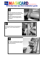
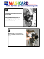
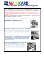
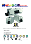
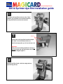
www.ultramagicard.com
300 & Sprinter dye-film installation guide
1
To remove the dye-film carrier turn the “Dzus”
fastener ring a quarter turn counter-clockwise,
the dye film carrier can then be removed.
2
Notches
Remove the roll of dye film from its wrapper
and slide it over the bottom feed core.
Also fit an empty take up roll over the top core.
Important:Ensure the two locating notches are facing to
the left on both the top and bottom rolls, as
shown in diagram right>>>.
3
Replace the Film Carrier, with the empty take up
spool facing the top.
www.ultramagicard.com
300 & Sprinter dye-film installation guide
4
It may be necessary to turn the take-up
spool drive gear to ensure the two notches
in the spool locate correctly with the
locking pins.
Manually turn the Spur Gear until the
notches on the spool engage with the
locking pins.
5
Turn the 'Dzus' Fastener 1/4 turn clockwise to
lock in place. Lay the ring flat against the
panel
6
Pull about 6" of dye film off the roll of dye
film, observing that it should be coming
off the top of the roll.
www.ultramagicard.com
300 & Sprinter dye-film installation guide
7
Avoid touching the tip of the thermal printhead
with your hands.
Feed the leading edge of the dye film over
the top of the Thermal Printhead and
beneath the guide bar, stick the leading
edge on the dye film to the take up spool
with the white label provided.
8
Wind the dye film on a couple of turns to
ensure it is centrally positioned on the take
up core.
www.ultramagicard.com
300 & Sprinter dye-film installation guide
Special Note:
How to fit UR3 Continuous Resin Dye Film and UR10 Single Colour Dye Film
Before fitting the continuous resin black thermal transfer film dye film or the UR10 single
colour dye film a small modification must be carried out on the take-up spool spigot before
operating the printer.
As this dye film has no panels the optical sensors are inoperative, so for correct operation it is
important that this modification is carried out.
Please Note: Should you revert back to using any other dye film this modification must be
reversed.
The modification is performed as follows:
1
Switch off the Magicard printer and lift up the Mechanism Top
Cover to the vertical position and remove the dye film and take-up
spools.
ON PRINTERS WITH WHITE PLASTIC DYE FILM TAKE-UP GEAR
Remove the steel pin, which normally engages with the recess in the dye film take-up spool.
This pin is a press fit in the dye film take-up spigot adjacent to
the large plastic spur gear as illustrated in Figure 2.
2
It may be removed by means of a pair of pliers or a small "Mole"
wrench, using a twisting and pulling action to remove it.
With each new roll of continuous black dye film, a rubber washer
is provided, this washer should be fitted on the plastic dye takeup spigot adjacent to the large spur gear, and before fitting the
dye film take-up spool.
ON PRINTERS WITH BLACK DYE FILM TAKE-UP GEAR
Using a Phillips head screwdriver, turn the locking
screw on the centre of the dye film take-up spigot
anti-clockwise until the tab (which normally engages
in the recess in the dye film take-up spool) drops
flush with the dye film take-up spigot. See Figure 3.
3