1
®
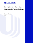
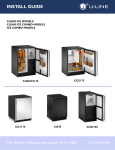
USE AND CARE GUIDE
COMBO® MODELS &
MANUAL DEFROST
ICE MAKERS
CO29
BI2115
CO1175
ADA15IM
SP18
BI95
The Built-In Undercounter Leader Since 1962
BI98
U-LINE.COM
Introduction
Please Record Your Model Information
Building on 45 years, U-Line has captivated those with an
appreciation for the finer things with exceptional design, inspired
innovations and attention to even the smallest details.
U-Line is synonymous with premium built-in under counter ice
making, refrigeration and wine storage appliances, the U-Line
Corporation is committed to luxury under the counter. U-Line is
known and respected for unwavering dedication to product
innovation, quality and selection. A bold and broad line of models
is the product of visionaries in the pursuit of distinctive living
environments in the kitchen and spaces beyond.
In 1962, Henry Uihlein founded U-Line Corporation as an
outgrowth of Ben-Hur Freezer Company and was the first to
develop and patent an automatic stand-alone under counter
residential ice maker. His foresight and determination to develop
new ideas and to succeed when there were no clear guidelines or
solutions are evident today. The Milwaukee, Wisconsin based
family operated business provides continuity and vision from which
innovations continue to be born.
Going forward, U-Line will continue offering best-in-class products
that build on the company's numerous patents and world firsts to
guide the under counter industry in realizing its unlimited
potential.
Read and save this Use and Care Guide.
FOR PRODUCT ASSISTANCE, CALL 1-800-779-2547
www.u-line.com
MILWAUKEE, WI U.S.A.
1
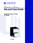
HIGH SIDE DESIGN PRESSURE 300 PSI
C
LOW SIDE DESIGN PRESSURE 140 PSI
Model/Modele:
UL
R
US
HOUSEHOLD
REFRIGERATOR AND/
OR FREEZER
LISTED 674R
Serial/Serie:
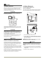
2
BTL
Congratulations on your purchase of a U-Line refrigeration
product.
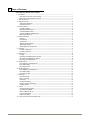
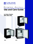
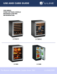
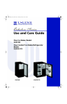
You will need your product model and serial number when you
request additional information or services. You can find this
information on the serial plate located on the upper right or back
wall in the interior of your product. This information also appears
on the warranty registration card.
Please record the model number (1), serial number (2), date of
purchase, and dealer contact information for your U-Line product
below:
Model Number:
________________________________________________
Serial Number:
________________________________________________
Purchase Date:
________________________________________________
IMPORTANT
READ all instructions in this guide completely before
using the appliance for the first time.
For future reference, keep this guide in a safe, accessible location.
If you need additional information or assistance, please contact ULine Corporation direct. Contact information appears on the back
cover of this guide.
Before Calling Service. If you think your U-Line product is
malfunctioning, read the OPERATION section of this guide to
understand clearly the function of the control. If the problem
persists, read the TROUBLESHOOTING GUIDE section of this
guide to help you quickly identify common problems, and provide
information on possible causes and remedies.
Dealer Name:
________________________________________________
Dealer Address:
________________________________________________
Dealer Telephone:
________________________________________________
Introduction to U-Line
1 Table of Contents
U-LineCombo® Models and Ice Makers
i - Introduction ................................................................................................................................................................. i
Read and save this Use and Care Guide. ......................................................................................................... i
Please Record Your Model Information ........................................................................................................... i
1 - Table of Contents .....................................................................................................................................................1
3 - Safety Precautions .....................................................................................................................................................3
Safety Alert Definitions ........................................................................................................................................3
General Precautions .............................................................................................................................................3
4 - Product Features .......................................................................................................................................................4
Ice Makers Feature: ..............................................................................................................................................4
ADA15IM Model Features: .................................................................................................................................4
Combo® Models Feature: ..................................................................................................................................4
CO1175 and BI2115 Model Feature: ...............................................................................................................4
BI2115 Model Features: .......................................................................................................................................4
5 - Product Operation ...................................................................................................................................................5
Air Flow ...................................................................................................................................................................5
Initial Startup ..........................................................................................................................................................5
Control Dial ...........................................................................................................................................................5
Adjusting AirTemperature ..................................................................................................................................6
Adjusting Ice Harvest ...........................................................................................................................................6
Checking Product Temperature ........................................................................................................................6
6 - Ice Maker ....................................................................................................................................................................7
Ice Maker Adjustment ..........................................................................................................................................7
Ice Maker Operation ............................................................................................................................................7
7 - Maintenance ...............................................................................................................................................................8
Leveling ....................................................................................................................................................................8
Removing and Installing Interior Shelves .........................................................................................................8
Removing and Installing Door Shelves .............................................................................................................9
Removing and Installing Grille ............................................................................................................................9
8 - Standard Doors ...................................................................................................................................................... 10
Door Alignment and Adjustment ................................................................................................................... 10
Door Reversability ............................................................................................................................................. 10
Reversing the door ............................................................................................................................................ 10
9 - Self-Closing Doors ................................................................................................................................................ 12
Door Alignment and Adjustment ................................................................................................................... 12
Door Reversability ............................................................................................................................................. 12
Reversing the door ............................................................................................................................................ 12
10 - Cleaning ................................................................................................................................................................. 14
Exterior Cleaning ............................................................................................................................................... 14
Interior Cleaning ................................................................................................................................................ 14
Defrosting ............................................................................................................................................................ 14
Condensor Cleaning .......................................................................................................................................... 15
Storage, Vacation and Moving ......................................................................................................................... 15
Product Disposal ................................................................................................................................................ 15
11 - Service .................................................................................................................................................................... 16
Normal Operating Sounds ............................................................................................................................... 16
Troubleshooting Guide ..................................................................................................................................... 16
Before Calling for Service ................................................................................................................................ 16
If Service is Required ......................................................................................................................................... 16
Replacement Parts ............................................................................................................................................. 16
12 - U-Line Corporation Limited Warranty .......................................................................................................... 17
U-Line Use and Care Table of Contents
1
2
U-Line Use and Care Guide
3 Safety Precautions
General Precautions
IMPORTANT
• PLEASE READ all instructions before installing,
operating, or servicing the appliance.
• Proper installation procedures must be followed when
completing an installation or relocation of a unit.
Consult the installation guide before any installation
begins. U-Line contact information appears on the rear
cover of this guide.
• This unit requires connection to a dedicated 15 Amp
grounded (three-prong), polarized receptacle, installed
by a qualified electrician, compliant with applicable
electrical codes.
Safety Alert Definitions
Throughout this guide are safety items labeled with a Danger,
Warning or Caution based on the risk type:
Use this appliance for its intended purpose only and follow these
general precautions with those listed throughout this guide:
DANGER
RISK OF CHILD ENTRAPMENT. Before you throw away your
old refrigerator or freezer, take off the doors and leave shelves
in place so children may not easily climb inside.
WARNING
SHOCK HAZARD - Electrical Grounding Required.
• Never attempt to repair or perform maintenance on
the unit until the electricity has been disconnected.
• Never remove the round grounding prong from the
plug and never use a two-prong grounding adaptor.
• Altering, cutting of power cord, removal of power
cord, removal of power plug, or direct wiring can
cause serious injury, fire and or loss of property and
or life, and will void the warranty.
• Never use an extension cord to connect power to the
unit.
• Always keep your working area dry.
WARNING
DANGER
Danger means that failure to follow this safety statement will
result in severe personal injury or death.
Install provided Anti-Tip kit on all Wine Captain
Models and Beverage Centers. Serious personal injury
could occur.
CAUTION
WARNING
• Use care when moving and handling the unit. Use gloves
to prevent personal injury from sharp edges.
• If your model requires defrosting, DO NOT use an ice
pick or other sharp instrument to help speed up
defrosting. These instruments can puncture the inner
lining or damage the cooling unit. DO NOT use any type
of heater to defrost. Using a heater to speed up
defrosting can cause personal injury and damage to the
inner lining.
Warning means that failure to follow this safety
statement could result in serious personal injury,
property or equipment damage.
CAUTION
Caution means that failure to follow this safety statement
may result in minor or moderate personal injury, property
or equipment damage.
IMPORTANT
• Do not lift unit by door handle.
• Never install or operate the unit behind closed doors.
Be sure front grille is free of obstruction. Obstructing
free airflow can cause the unit to malfunction and will
void the warranty.
• Failure to clean the condenser every six months can
cause the unit to malfunction. This could void the
warranty.
• Allow unit temperature to stabilize for 24 hours before
use.
• Do not Block any internal Fans
Use only genuine U-Line replacement parts. Imitation
parts can damage the unit, affect its operation or
performance and may void the warranty.
U-Line Safety Precautions
3
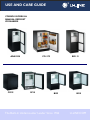
4 Product Features
Ice Makers Feature:
High ice production and storage. ADA15IM, BI2115 and BI98
models produce up to 25 pounds of ice per day and store 25
pounds. BI95 and SP18 models produce up to 23 pounds of ice per
day and store 12 pounds. Combo® Models produce up to 18
pounds of ice per day and store 13 pounds and provide both ice
production and refrigeration in one. CO1175 has 4.2 cubic feet
and CO29 has 2.1 cubic feet refrigeration storage.
No drain required. Easy and inexpensive to install. Only requires
a 1/4" outside diameter water line.
Conserves on water. Uses under 3 gallons of water to produce
22 pounds of ice or 2-1/4 gallons for 18 pounds.
Built-in or freestanding. Provides custom look when built-in
with no additional venting clearance needed on sides, top or rear.
Do not obstruct the grille.
Vinyl-clad cabinet. Textured, rich appearance. More resistant to
scratching, peeling and flaking.
Door will accept a 1/4" panel. Ability to match surrounding
décor and cabinets. Black and white models only.
Integrated handle. Does not add depth to the cabinet when
built in. Black and white models only.
Field-reversible doors. Flexible installation options. All models
with black and white doors are field-reversible. Stainless steel
models must be order right- or left-hand hinged.
Flat recessed grille. Blends with the other models and
integrates with surrounding cabinetry.
Defrost Type: Manual Defrost
For indoor use only.
ADA15IM Model Features:
Factory installed door locks. Provides security and safety.
Stainless steel models. Offers a bold stainless steel habdle,
stainless steel wrap door. Stainless steel models must be ordered
right or left-hand hinged
Combo® Models Feature:
Mechanical Temperature Control. Provides ability to set the
temperature.
Adjustable tempered glass shelves. Sleek, streamlined
interior. Allows flexible shelf locations to meet varying food and
beverage storage needs. Three in 75, Two in 29.
In-door storage shelves. Two adjustable on 75 model and 3 on
29 model. Easiest access storage area right where you need it.
Adjustable to allow flexible storage options
CO1175 and BI2115 Model Feature:
Adjustable leveling legs. Achieve a more precise under counter
fit. Durable, strong legs will not bend when unit is installed.
Stainless steel model. Offers a bold stainless steel handle,
stainless steel wrap door. BI2115 has full wrap. CO1175 has black
"cap" on top and bottom of the door. Stainless steel models must
be order right- or left-hand hinged.
BI2115 Model Features:
Optional 3/4" full overlay door panel kit. Provides a fully
integrated appearance with surrounding décor while maintaining
zero door clearance. Easy to install. Black and white models only.
Must order kit number U-OL2115.
Self-closing door. Engages when the door is open 8-10". Ensures
a positive door seal and prevents door bounceback.
Contemporary grille design. Integrates seamlessly with
surrounding cabinetry.
4
U-Line Combo Model and Ice MakerProduct Features
1 Product Operation
Initial Startup
Air Flow
All U-Line controls are preset at the factory. Initial startup requires
no adjustments.
IMPORTANT
The unit requires proper air flow to perform at its highest
efficiency. Do not block the front grille or internal fans at
any time, or the unit will not perform as expected. Do not
install the unit behind a door.
IMPORTANT
U-Line recommends allowing the unit to run overnight
before loading refrigerator or freezer with product.
IMPORTANT
ON
OFF
On ice maker equipped units, it is possible that dirt or
scale will dislodge in the water line. Always throw away all
ice cubes made during the first two to three hours of
operation.
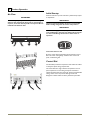
To turn the unit on or off:
Press the rocker switch located below the temperature control
dial in the center of the grille(2), inside the door on the front
panel, or behind the grille.
Control Dial
Combo Models provide two temperature zones within the cabinet
to satisfy the specific storage requirements.
The control dial sets a single continuous temperature. This setpoint temperature is a base setting used by the controller to
maintain the temperature zone in the unit. The factory default MID
setting, number 3 or 4 set-point for Beverage Center and
Refrigerator models is 38°F. The factory default set-point Wine
U-Line Product Operation
5
Adjusting AirTemperature
Checking Product Temperature
Combo Models
IMPORTANT
• Adjust the set point temperature in single increments,
and wait 24 hours for the temperature to stabilize
before rechecking.
• Factory recommended set-point is MID setting on dial
control.
To adjust the set point temperature:
Adjust the temperature by turning the numbered dial (1) in
small increments.
To check the actual product temperature in the unit.
1. Partially fill a plastic (nonbreakable) bottle with water.
1
2. Insert an accurate thermometer.
2
3. Tighten the bottle cap securely.
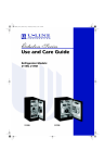
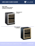
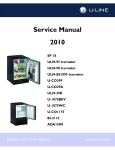
Adjusting Ice Harvest
4. Place the bottle in the desired area for 24 hours.
BI Models
5. Avoid opening the unit during the testing period.
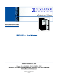
1. Remove the front grille (see MAINTENANCE).
6. After 24 hours, check the temperature of the water. If required,
adjust the temperature control in a small increment (See
ADJUSTING TEMPERATURE).
2. Turn the adjusting screw (3) using a flat tip screwdriver in a
small increment clockwise for a COLDER setting (slower ice
production) or counterclockwise for a WARMER setting (faster
ice production).
Causes which affect the internal temperatures of the
cabinet include:
• Temperature setting.
3. Replace the front grille (two screws).
• Ambient temperature where installed.
• Installation in direct sunlight or near a heat source.
• The number of door openings and the time the door is open.
C
OL
6
• The time the internal light is illuminated. (This mainly affects
product on the top rack or shelf.)
DE R
3
• The front grille or condenser are obstructed.
U-Line Product Operation
6 Ice Maker
Ice Maker Operation
Ice Maker Adjustment
When the ice bucket is full, the ice making mechanism will shut off.
However, the refrigeration system will continue to cool and
maintain the cube supply. Frost-free ice maker units have lower ice
production than manual defrost units.
Ice Cube Thickness Adjustment.
Interval - As Required
On ice maker equipped models, adjust the cube size by changing
water amount injected into the ice maker assembly as follows:
IMPORTANT
Do not place cans or bottles in the ice compartment
because they will freeze.
OFF
1
ON
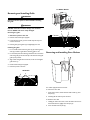
To turn off ice production: Raise the bin arm into an upright
and locked position. The unit will preserve temperature for ice
storage.
2
IMPORTANT
If not intending to use the ice maker turn the water
supply valve off, it is important to raise the bin arm of the
ice maker (Figure 1). Failure to raise the bin arm may
result in damage to the water valve.
Certain sounds are normal during the unit’s operation. You may
hear the compressor or fan motor, the water valve, or ice
dropping into the ice bucket.
WARNING
NEVER use an ice pick, knife or other sharp instrument
to separate cubes. Shake the ice bucket instead.
During periods of limited use or high ambient temperatures, it is
common for cubes to fuse together. Gently shake the bucket to
break apart cubes. If not using the ice maker regularly, empty the
ice bucket periodically to ensure fresh cubes.
It is normal for cubes to appear cloudy. The cause is air trapped in
the water because of fast freezing. It is not caused by the health,
taste or chemical make up of the water. It is the same air that is in
every glass of water you drink.
Remove the ice bucket for emptying and cleaning. To remove the
ice bucket, raise the bin arm and remove the bucket from the ice
compartment. Use the ice bucket for ice storage only.
1. Remove the ice maker assembly cover (1).
2. Find the adjusting screw on the ice maker assembly control box
(2). The adjusting screw is just below the minus (-) and plus (+)
signs on the control box.
NOTE: Adjust in small increments. Too large of an adjustment could cause the unit to malfunction.
CAUTION
Too large of an adjustment to the screw can cause the
water to overflow the ice maker and can cause property
damage.
3. Turn the adjusting screw toward the minus (-) sign (clockwise)
for smaller cubes or toward the plus (+) sign (counterclockwise)
for larger cubes.
4. Install the ice maker assembly cover.
U-Line Ice Makers
7
7 Maintenance
Removing and Installing Interior Shelves
Leveling
IMPORTANT
Unit must be level, for proper door and ice maker (if
equipped) operation.
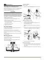
For models equipped with glass shelves having shelf supports,
remove the shelves as follows:
1
1. Open door completely.
For Models with adjustable leveling feet:
1. Use a level to check the levelness of the unit from front to back
and from side to side. Place the level along top edge and side
edge as shown (1).
2. If the unit is not level, rotate the adjustable leveling legs to raise
or lower each corner of the unit (5) as necessary.
2. Grasp the shelf edge in the center and slide the shelf from the
unit.
Insert the shelves as follows:
Reposition the shelf as required, ensure the raised white edge
strip is toward the rear of the unit and graphics, if applied, are
on the underside of the shelves.
3. Check levelness after each adjustment and repeat the previous
steps until the unit is level.
For Models without adjustable leveling feet:
IMPORTANT
The unit must be located on a level surface, for proper
door and ice maker (if equipped) operation.
Use a level to check the levelness of the unit from front to back
and from side to side. Place the level along top edge and side
edge as shown (1).
8
U-Line Combo® Models and Ice Makers Maintenance
Ice Maker Models
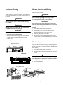
Removing and Installing Grille
2 1
WARNING
Disconnect electric power to the unit before removing
the grille.
WARNING
4
DO NOT touch the condenser fins(4). The condenser
fins are SHARP and can be easily damaged.
6
Removing the grille.
1
1. Disconnect power to the unit.
2. Remove control knob (6) if equipped.
3. Loosen the two screws (1). Some models may have only one
screw in the center.
4. Remove grille (2) and grille cap (if equipped)(3) from unit.
2
Installing the grille:
1. For 15 and 29 models make sure grille cap (3) is behind grille in
slots (2) provided in grille before attaching grille to unit.
2. For 75 models place the hook-hinge located on the rear bottom
side of the grille (2) onto the front lip of the unit base. Swing the
grille up into position.
5
Removing and Installing Door Shelves
1
3. Align cabinet and grill holes and secure, but do not overtighten
grille screws (1).
4. Install control knob (6) if equipped.
5. Reconnect power to the unit.
29 Models
1
3
2
6
2
For models equpped with door shelves:
To remove the door shelf:
1. Grasp shelf in center, and lift until the shelf notches (1) clear
the pins (2).
2. Carefully pull the shelf away from the door.
To install the door shelf:
1. Holding the shelf in the center, center the shelf in the door at
the desired location, slightly above the pins (2).
2. Lower the shelf onto the pins (2).
U-Line Combo® Models and Ice Makers Maintenance
9
To reverse the door:
8 Standard Doors
Remove grille:
Door Alignment and Adjustment
Remove the grille see MAINTENANCE section of this guide.
Align and adjust the door if it is not level, or is not sealing properly.
If the door is not sealed the unit may not cool properly, or
excessive frost may form in the interior.
IMPORTANT
Properly aligned, the door’s gasket should be firmly in
contact with the cabinet all the way around the door (no
gaps). Carefully examine the door’s gasket to assure that
it is firmly in contact with the cabinet. Also make sure the
door gasket is not pinched on the hinge side of the door.
To align and adjust the door:
1. Loosen (do not remove) top and bottom hinge screws.
2. Align door squarely with cabinet.
Remove top hinge, and door:
3. Make sure gasket is firmly in contact with cabinet all the way
around the door (no gaps).
1. Hold door to keep it from falling.
4. Tighten bottom hinge screws.
5. Tighten top hinge screws.
2. Remove top hinge from cabinet by removing three or four
screws, depending on model.
3. Remove door by tilting forward and lifting door off bottom
hinge.
Door Reversability
Location of the unit may make it desirable to mount the door on
the opposite side of the cabinet.
4. Remove three or four plastic screw plugs from hinge holes on
the opposite side. Reinstall into holes where the hinge was
Models with black and white doors are field-reversible.
Stainless steel models with glass doors without locks are fieldreversible.
Stainless steel models without glass doors must be ordered rightor left-hand hinged.
Reversing the door
The Hinge hardware will be removed and reinstalled on the
opposite side of the cabinet.
The hinge plate is flipped over when it is reinstalled on the
opposite side of the cabinet.
removed. Ensure not to scratch cabinet.
Remove bottom hinge:
Plastic
Plug Hole
Plastic
Plug Hole
1. Remove bottom hinge from cabinet. Some models will have a
gusset with two screws. Other models will have a plate with
three screws.
2. Remove corresponding screws on opposite side of cabinet. On
Right Side
Door Swing
10
Left Side
Door Swing
U-Line Standard Door Alignment and Reversal
1
Install bottom hinge:
Prepare door for reinstallation:
1. If you have a plate hinge, reorient the pivot screw so it
protrudes the opposite direction form the hinge. Remove the
pivot screw from the hinge. Turn the plate over and reinstall
the screw.
For black or white doors:
1. Remove plastic hole plug from top of door handle and reinstall
on opposite side.
2. Align hinge outer edge with cabinet. For models with a plate
hinge, the flat edge of the hinge alignes with the outer edge of
the cabinet.
2. Remove plastic hinge bushing on bottom of door and reinstall on
opposite side. Clean out bushing hole in door bottom with a
screwdriver if necessary.
Install two or three screws, depending on model. Replace nuts if
used.
3
4
Install top hinge, and door:
2
1
1. Reorient the pivot screw so it protrudes the opposite
direction from the hinge. Remove the pivot screw from the
hinge. Turn the plate over and reinstall the screw.
2. Hold door to keep it from falling.
Prepare door for reinstallation:
3. Lift the door on to the bottom hinge.
For stainless steel models with glass doors:
4. Align flat edge of the hinge with the outer edge of the unit.
3. Stainless glass doors are flipped upside down to be reversed.
5. Install three or four screws, depending on model.
4. Lay the door on it’s side. Remove the plastic hole plug (1) and
install in the corner opposite of where it was removed.
Align and adjust the door:
5. Remove the plastic hinge bushing (2) and install in the corner
opposite of where it was removed.
6. Remove the U-Line nameplate (3) from door. This will reveal
mounting holes for the door actuator bracket.
1. Align and adjust the door, see DOOR ALIGNMENT AND
ADJUSTMENT above.
Install grille:
Install the grille, see MAINTENANCE section of this guide.
7. Remove door actuator (4) from door. Be sure to only remove
the two screws holding the actuator to the door. Reinstall the
actuator (4) on the opposite end of the door where the
nameplate was removed.
8. Install new nameplate where the actuator assembly was
removed.
9. Install screws into holes on opposite side, where the hinge was
removed. Replace nuts if used.
U-Line Standrd Door Alignment and Reversal
11
9 Self-Closing Doors
Door Alignment and Adjustment
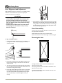
Align and adjust the door if it is not level, or is not sealing properly.
If the door is not sealed the unit may not cool properly, or
excessive frost may form in the interior.
IMPORTANT
• Properly aligned, the door’s gasket should be firmly in
contact with the cabinet all the way around the door
(no gaps). Carefully examine the door’s gasket to
ensure that it is firmly in contact with the cabinet. Also
make sure the door gasket is not pinched on the hinge
side of the door.
• The door will not be flush with the top of the cabinet.
The top edge of the door will be 1/8 in. (3.175 mm)
below the cabinet top.
1/8"
(3.175 mm)
4
5. After adjustment is complete, remove the door closers from the
bottom hinge, clean thoroughly and apply petroleum jelly to the
mating surfaces of the closers. Be sure that pins on closers align
with holes in the door and bottom cabinet hinge plates. Mount
door and install top hinge pivot pin.
Door Reversability
Location of the unit may make it desirable to mount the door on
the opposite side of the cabinet.
Models with black and white doors are field-reversible.
Stainless steel models must be ordered right- or left-hand hinged.
Reversing the door
To align and adjust the door:
1. Compare the top edge of the door (opposite the hinges) to the
top edge of the cabinet and note the type (up or down) of
adjustment needed.
1
2
3
2. Remove the top hinge pivot pin with a Phillips screwdriver and
lift door off bottom hinge pin. Be careful not to lose the door
closer insert sets.
3. Turn the door upside down and inspect the hinge plate mounting
holes. The plate has slotted mounting holes. Loosen but do not
remove the two hinge plate screws(1).
4. If door edge opposite the hinges needs to move up, move plate
toward outside of door(2). If door edge needs to move down,
move plate toward inside of door(3). Repeat until top edge of
door is parallel with top of cabinet and tighten screws (1)
securely.
12
The Hinge hardware will be removed and reinstalled on the
opposite side of the cabinet.
The top hinge hardware will be reinstalled on the bottom of the
opposite side of the cabinet.
The bottom hinge hardware will be reinstalled on the top of the
opposite side of the cabinet.
U-Line Self-Closing Door Alignment and Reversal
To reverse the door:
Remove existing bottom hinge.
Remove the existing bottom hinge (three screws) (2).
3
1
Reinstall hinge to top opposite.
Install the hinge just removed from the bottom to the TOP
opposite side of the cabinet (three screws) (2).
Reinstall Hole Plugs.
Install plastic screw plugs (three each, top and bottom) (3) into
holes where hinge hardware was removed.
2
Remove door:
1
1. Hold door to keep it from falling.
2. Remove hinge screw pin (1) from top hinge using a Phillips
screwdriver.
3. Remove door by tilting forward and lifting door off bottom hinge
closer inserts.
4. Reinstall hinge screw pin (1) into top hinge using a Phillips
screwdriver.
Remove hole plugs.
NOTCH
Remove plastic screw plugs (three each, top and bottom) (3)
from new hinge location. Save for reinstallation later.
5
Remove existing top hinge.
Remove existing top hinge (three screws) (2).
Prepare door for reinstallation.
1. Remove plastic hole plug from top of door handle and reinstall
on opposite side.
2. With bottom of door facing up, remove pivot plate (5) (two
screws).
3. Flip over and install pivot plate on opposite side of door. Ensure
notch in plate faces center.
4
ULI
Install Door.
1. Hold door upright and tilted forward.
4
2. Lift door on to bottom hinge closer inserts.
Reinstall hinge to bottom opposite.
3. Tilt door forward into position.
1. Install the hinge just removed from the top to the BOTTOM
opposite side of the cabinet (three screws) (2).
4. Hold door to keep it from falling.
2. Remove the two door closer inserts (4) from the existing
bottom hinge.
3. Install door closer inserts as shown on the new bottom hinge
(4).
5. Reinstall hinge screw pin (1) into top hinge using a Phillips
screwdriver.
Align and adjust the door:
Align and adjust the door, see DOOR ALIGNMENT AND
ADJUSTMENT above.
U-Line Self-Closing Door Alignment and Reversal
13
.
10 Cleaning
Defrosting
Manual Defrost Models
Exterior Cleaning
Vinyl Clad (Black or White) Models:
• Clean surfaces with a mild detergent and warm water solution.
Do not use solvent-based or abrasive cleaners. Use a soft
sponge and rinse with clean water. Wipe with a soft, clean
towel to prevent water spotting.
• Clean any glass surfaces with a non-chlorine glass cleaner.
Unit is a manual defrost model and will require occasional
defrosting. When there is build-up of 1/4” or more of frost
manually defrost the unit. Defrost every two months minimum.
• Ensure the door is closing and sealing properly.
• High ambient temperature and excessive humidity can also
produce frost.
CAUTION
Stainless Models:
• Stainless door panels, handles and frames can discolor when
exposed to chlorine gas, pool chemicals, saltwater or cleaners
with bleach.
• Keep your stainless unit looking new by cleaning with a good
quality all-in-one stainless steel cleaner polish monthly. For best
results use Claire® Stainless Steel Polish and Cleaner, which can
be purchased from U-Line Corporation (Part Number 173348).
Comparable products are acceptable. Frequent cleaning will
remove surface contamination that could lead to rust. Some
installations may require cleaning weekly.
• Do not clean with steel wool pads.
• Do not use stainless steel cleaners polishes on any glass
surfaces.
• Clean any glass surfaces with a non-chlorine glass cleaner.
• Do not use cleaners not specifically intended for
stainless steel on stainless surfaces (this includes glass,
tile and counter cleaners).
• If any surface discoloring or rusting appears, clean it quickly
with Bon-Ami® or Barkeepers Friend Cleanser® and a
nonabrasive cloth. Always clean towards the grain. Always finish
with Claire Stainless Steel Polish and Cleaner or comparable
product to prevent further problems.
• Using abrasive pads such as Scotchbrite™ will cause
the graining in the stainless to become blurred.
• Rust not cleaned up promptly can penetrate the surface of the
stainless steel and complete removal of the rust may not be
possible.
DO NOT use an ice pick or other sharp instrument to
help speed up defrosting. These instruments can puncture
the inner lining or damage the cooling unit. DO NOT use
any type of heater to defrost. Using a heater to speed up
defrosting can cause personal injury and damage to the
inner lining.
To defrost:
1. Disconnect power to the unit.
2. For combo models remove all products from the interior.
3. Remove ice bucket and discard ice.
4. Place towel or other absorbent materialon bottom of ice bin.
For combo models also place in bottom of unit.
5. Fill the ice bucket half full with warm, not hot water. This will
help the unit defrost faster.
6. Place the ice bucket back into the unit on top of the towel or
other absorbent material.
7. Prop the door in an open position (2 in. (5 cm) minimum).
8. After about 1 hour remove the ice bin and discard water.
9. Allow the frost to melt naturally.
10. After the frost melts completely clean the interior and all
removed components. (See INTERIOR CLEANING)
IMPORTANT
Interior Cleaning
DO NOT clean ice bucket using a dishwasher. The bucket
is not dishwasher safe and will be damaged.
• Disconnect power to the unit.
• Clean the interior and all removed components using a mild
nonabrasive detergent and warm water solution applied with a
soft sponge or non-abrasive cloth.
• Rinse the interior using a soft sponge and clean water.
11. When the interior is dry, reconnect power and turn unit on.
NOTE: To safeguard against contaminates in ice, discard first
three batches of ice after defrosting.
• Do not use any solvent-based or abrasive cleaners.
These types of cleaners may transfer taste to the interior
products and damage or discolor the interior.
14
U-Line Combo® Models and Ice Makers Cleaning
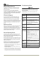
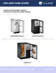
Condensor Cleaning
Storage, Vacation and Moving
Interval - Every Six Months
If not using the unit for an extended period, or otherwise stored,
follow these steps completely:
To maintain operational efficiency, keep the front grille free of dust
and lint, and clean the condenser every three months. Depending
on environmental conditions, more or less frequent cleaning may
be necessary.
WARNING
Electrical Shock Hazard. Disconnect power before
servicing. Before operating, replace all panels. Failure
to do so may result in death or electrical shock.
WARNING
Disconnect electric power to the unit before cleaning
the condenser.
IMPORTANT
If the ambient temperature is expected to drop below
50°F, turn off and unplug unit, and drain all water from the
unit to prevent freezing damage not covered by the
warranty.
WARNING
DO NOT touch the condenser fins. The condenser fins
are SHARP and can be easily damaged.
1. Remove all consumable contents from the unit.
IMPORTANT
2. Disconnect the power cord from its outlet, and leave it
disconnected until the unit is returned to service.
DO NOT use any type of cleaner on the condenser unit.
3. Clean and dry the interior of the cabinet.
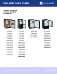
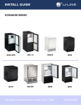
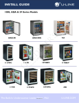
1. Remove the grill. (See MAINTENANCE)
4. During periods of nonuse, the cabinet must remain open to
prevent formation of mold and mildew. Open door a minimum
of 2 in. (5 cm) to provide the necessary ventilation.
2. Clean the condenser coil (4) using a using a soft brush with a
“combing” action or vacuum cleaner. Do not touch the
condenser coil.
3. Install the grill. (See MAINTENANCE)
Product Disposal
29 Models
Typical Model Shown
If the unit is being removed from service for disposal, check and
obey all Federal, State and or Local regulations regarding the
disposal and recycling of refrigeration appliances, and follow these
steps completely:
4
1. Remove all consumable contents from the unit.
2. Disconnect power to the unit and unplug the power cord from
its outlet.
75 Models
4
DANGER
Typical Model Shown
RISK OF CHILD ENTRAPEMENT. Before you throw away
your old refrigerator or freezer, take off the doors and leave
shelves in place so children may not easily climb inside.
3. Remove the cabinet door.
Icemaker Models
Typical Model Shown
1
2 1
2
4
4
5
U-Line Combo® Models and Ice MakersCleaning
15
11 Service
Troubleshooting Guide
Before Calling for Service
If you think your U-Line product is malfunctioning, read the
OPERATION section of this guide to understand clearly the
function of the control.
If the problem persists, read the NORMAL OPERATING
SOUNDS and TROUBLESHOOTING GUIDE section of this guide
to help you quickly identify common problems, and possible causes
and remedies. Most often, this will resolve the problem without
the need to call for service.
DANGER
ELECTROCUTION HAZARD. Never attempt to repair or
perform maintenance on the unit until disconnecting the
main electrical power.
Troubleshooting - What to check when problems occur:
Problem
Possible Cause and Remedy
Interior Light
Does Not
Illuminate.
The light bulb may be defective.(See MAINTENACE)
Light Remains
on When Door
is Closed.
Adjust light actuator bracket ob bottom of door.
When you call, you will need your product Model and Serial
Numbers. This information can be recorded inside the front cover
of this guide. It also appears on the Model and Serial number plate
located on the upper right or rear wall of the interior of your
product.
Unit Develops
Frost on
Internal
Surfaces.
Unit is a manual defrost model that will require
occasional defrosting. When there is build-up of 1/4”
or more, manually defrost the unit.
Ensure the door is closing and sealing properly.
High ambient temperature and excessive humidity
can also produce frost.
Replacement Parts
Unit Develops
Condensation
on External
surfaces
The unit is exposed to excessive humidity, moisture
will dissipate as humidity levels increase.
Product is
Freezing in
Combo Models.
Adjust the temperature to a warmer set-point. (See
OPERATION)
Product is Not
Cold Enough in
Combo models.
Air temperature does not indicate product
temperature. See OPERATION - Checking Product
Temperature.
Adjust the temperate to a cooler set-point. (See
OPERATION)
Ensure unit is not located in excessive ambient
temperatures or in direct sunlight.
Ensure the door is closing and sealing properly.
Ensure the interior light has not remained on too
long.
Ensure nothing is blocking the front grille, found at
the bottom of the unit.
Ensure the condenser coil is clean and free of any dirt
or lint build-up.
Ice Cubes
Sticking
Together
During periods of limited use or high ambient
temperatures, it is common for cubes to fuse
together. Gently shake the bucket to break apart
cubes.
No Ice
Production
Ensure the bin arm is not in the up (off) position.
Not Enough Ice
Ensure the condenser coil is clean and free of any dirt
or lint build-up.
Water in Bucket
Ensure cube size adjustment is not se too high.
If Service is Required
If you do not understand a troubleshooting remedy, or your
product needs service, contact U-Line Corporation directly.
Contact information appears on the rear cover of this guide.
When you need replacement parts, always request genuine U-Line
replacements. U-Line designs and engineers products using
components that work efficiently, and provide superior service life
and performance. The use of aftermarket parts or components
may affect the safety, operation, performance or durability of your
product, and may also void its warranty.
Normal Operating Sounds
All models incorporate rigid foam insulated cabinets to provide
high thermal efficiency and maximum sound reduction for its
internal working components. Despite this technology, your model
may make sounds that are unfamiliar.
Normal operating sounds may be more noticeable because of the
unit’s environment. Hard surfaces such as cabinets, wood, vinyl or
tiled floors and paneled walls have a tendency to reflect normal
appliance operating noises.
Listed below are common refrigeration components with brief
description of the normal operating sounds they make. NOTE:
Your product may not contain all the components listed.
• Compressor: The compressor makes a hum or pulsing sound
that may be heard when it operates.
• Evaporator: Refrigerant flowing through an evaporator may
sound like boiling liquid.
• Condenser Fan: Air moving through a condenser may be heard.
• Automatic Defrost Drain Pan: Water may be heard dripping or
running into the drain pan when the unit is in the defrost cycle.
16
U-Line Combo® Models and Ice Makers Service
U-Line Corporation Limited Warranty
1. U-Line Corporation ("U-Line") warrants each U-Line
product to be free from defects in materials and
workmanship for a period of one year from the date of
purchase. U-Line further warrants the sealed system
(consisting of the compressor, the condenser, the
evaporator, the hot gas bypass valve, the dryer and the
connecting tube) in each U-Line product to be free from
defects in materials and workmanship for a period of five
years from the date of purchase.
2. During the initial one year warranty period for all ULine products U-Line shall: (1) repair any product or
replace any part of a product; and (2) for all Marine, RV
and Domestic U-Line products sold and serviced in the
United States (including Alaska and Hawaii) and Canada,
U-Line shall be responsible for the labor costs performed
by a U-Line authorized service company, incurred in
connection with the replacement of any defective part.
During years two through five of the warranty period for
the sealed system, U-Line shall: (1) at U-line’s option repair
or replace any part of the sealed system; and (2) for all
Marine, RV and Domestic U-Line products sold and
serviced in the United States (including Alaska and
Hawaii) and Canada, U-Line shall be responsible for the
labor costs incurred in connection with the replacement
of any defective part of the sealed system. All other
charges, including transportation charges for
replacements under this warranty and labor costs not
specifically covered by this warranty, shall be the
responsibility of the purchaser. This warranty extends
only to the original purchaser of the U-Line product. The
registration Card included with the product should be
promptly completed by you and mailed back to U-Line or
you can register on-line at www.u-lineservice.com.
continue to be covered by the warranty terms set forth in
Paragraphs 1 and 2 above, to the extent such models:
A. Are subjected to temperatures between 50 and 100
degrees Fahrenheit. Although these products will
function in ambient temperatures below 50 degrees and
above 100 degrees Fahrenheit, performance may decline.
Performance degradation due to operating above or
below the designated ambient temperature range is not a
manufacturing defect and any issues resulting from
exposure to higher temperatures, such as spoiled food or
low ice production, are not covered under this warranty
policy; and/or
B. Come into contact with rain by virtue of outdoor use.
Exposure to other sources of water shall also cause this
warranty to be void, including flooding of the area in
proximity of the unit greater than 1/8” deep in water,
hurricanes, splashing of pool water, or directing a spray
from a hose or similar device into and around the unit.
5. If a product defect is discovered during the applicable
warranty period, you must promptly notify either U-Line
at P.O. Box 245040, Milwaukee, Wisconsin 53224 or at
800-779-2547 or the dealer from whom you purchased the
product. In no event shall such notification be received
later than 30 days after the expiration of the applicable
warranty period. U-line may require that defective parts
be returned, at your expense, to U-Line's factory in
Milwaukee, Wisconsin, for inspection. Any action by you
for breach of warranty must be commenced within one
year after the applicable warranty period.
3. The following conditions are excluded from this limited
warranty: damage caused by outdoor use; use of cleaners
other than the recommended stainless steel cleaners and
U-Line Clear Ice Maker cleaner; installation charges;
damages caused by disasters or acts of God, such as fire,
floods, wind and lightning; damages incurred or resulting
from shipping, improper installation, unauthorized
modification, or misuse/abuse of the product; customer
education calls; food loss and spoilage; door and water
level adjustments (except during the first 30 days from the
date of installation); defrosting the product; adjusting the
controls; door reversal; and cleaning the condenser.
6. THIS LIMITED WARRANTY IS IN LIEU OF ANY AND
ALL OTHER WARRANTIES, EXPRESS OR IMPLIED,
INCLUDING ANY IMPLIED WARRANTY OF
MERCHANTABILITY OR IMPLIED WARRANTY OF
FITNESS FOR A PARTICULAR PURPOSE, ALL OF WHICH
ARE DISCLAIMED. U-Line’s sole liability and your
exclusive remedy under this warranty is set forth in
the paragraphs above. U-Line shall have no liability
whatsoever for any incidental, consequential or
special damages arising from the sale, use or
installation of the product or from any other cause
whatsoever, whether based on warranty (express or
implied) or otherwise based on contract, tort or any
other theory of liability.
4. U-Lines' Outdoor Limited Warranty, set forth in this
Paragraph 4, shall apply to U-Line models deemed
suitable for outdoor use by Underwriters Laboratory
("UL") as noted in the U-Line Product Catalog, U-Line's
website and/or on the serial tag located inside the
product. Exposure to temperatures below freezing may
cause damage to the product. Damage resulting to the
product (and/or the surroundings) caused by this exposure
is not covered under this warranty. Such models shall
7. Some states do not allow limitations on how long an
implied warranty lasts or the exclusion or limitation of
incidental or consequential damages, so the above
limitations may not apply to you. This warranty gives you
specific legal rights, and you may also have other rights
which vary from state to state.
U-Line Warranty
®
USE AND CARE GUIDE
PRODUCT INFORMATION
Installation Guides with complete installation information, Custom Wood Panel Size Specifications & Installation
Instructions, CAD Drawings, Use and Care Guides, Specifications & Feature Benefits are available for viewing
and download on-line at www.u-line.com/specs/.
SERVICE INFORMATION
If you have a problem with this appliance, your use and care guide has troubleshooting information to help you
quickly identify common problems and provide information on possible cause and remedy. Answers to
Customers Frequently Asked Questions are available at www.u-line.com/customer/faq.cfm. You may contact
U-Line directly:
GENERAL INQUIRIES:
SERVICE ASSISTANCE:
U-Line Corporation
P.O. Box 245040
Milwaukee, Wisconsin 53224-9540 U.S.A.
Phone (414) 354-0300
FAX (414) 354-7905
Email: [email protected]
www.u-line.com
Phone (800) 779-2547
FAX (414) 354-5696
Email: [email protected]
www.u-lineservice.com
PARTS ASSISTANCE:
E-mail: [email protected]
ABOUT U-LINE
Building on 45 years, U-Line has captivated those with an appreciation for the finer things with exceptional
design, inspired innovations and attention to even the smallest details.
U-Line is synonymous with premium built-in undercounter ice making, refrigeration and wine storage appliances, the U-Line Corporation is committed to luxury under the counter. U-Line is known and respected for
unwavering dedication to product innovation, quality and selection. A bold and broad line of models is the product of visionaries in the pursuit of distinctive living environments in the kitchen and spaces beyond.
In 1962, Henry Uihlein founded U-Line Corporation as an outgrowth of Ben-Hur Freezer Company and was
the first to develop and patent an automatic stand-alone undercounter residential ice maker. His foresight and
determination to develop new ideas and to succeed when there were no clear guidelines or solutions are evident today. The Milwaukee, Wisconsin based family operated business provides continuity and vision from
which innovations continue to be born.
Going forward, U-Line will continue offering best-in-class products that build on the company's numerous patents and world firsts to guide the undercounter industry in realizing its unlimited potential.
The Built-In Undercounter Leader Since 1962
U-LINE.COM
©2009 U-Line Corporation
Publication Number 30264 7/2009 Rev. C