1
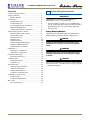
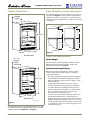
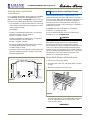
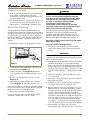
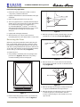
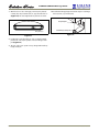
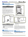
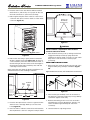
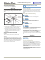
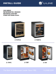
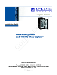
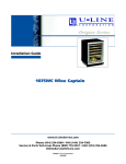
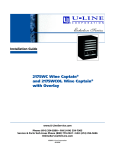
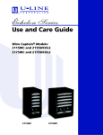
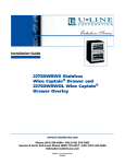
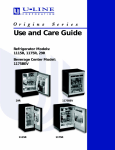
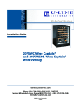
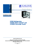
Installation Guide
2175BEVS Beverage Center
and 2175BEVOL2 Beverage
Center with Overlay
www.U-LineService.com
Phone (414) 354-0300 • FAX (414) 354-7905
Service & Parts Tech Lines Phone (800) 779-2547 • FAX (414) 354-5696
[email protected]
©2008 U-Line Corporation
03/2008
2175BEVS/2175BEVOL2 Beverage Center
Contents
1-Follow Safety Precautions . . . . . . . . . . . . . . . . . . . . .
2-Inspect and Plan . . . . . . . . . . . . . . . . . . . . . . . . . . . . .
Exterior Cleaning . . . . . . . . . . . . . . . . . . . . . . . . . .
3-Prepare Site . . . . . . . . . . . . . . . . . . . . . . . . . . . . . . . .
Cut-Out Dimensions . . . . . . . . . . . . . . . . . . . . . . . .
Product Dimensions . . . . . . . . . . . . . . . . . . . . . . . .
Door Swing/Clearances Information . . . . . . . . . . .
Other Site Requirements . . . . . . . . . . . . . . . . . . . .
Side-By-Side Installation Instructions . . . . . . . . . .
4-Prepare Racks and Door Frame . . . . . . . . . . . . . . . . .
Wine Rack Removal/Installation . . . . . . . . . . . . . .
Wood Trim Finishing . . . . . . . . . . . . . . . . . . . . . . .
Reversing the Door . . . . . . . . . . . . . . . . . . . . . . . . .
Overlay Frame . . . . . . . . . . . . . . . . . . . . . . . . . . . . .
Frame Preparation . . . . . . . . . . . . . . . . . . . . . . . . .
Prepare the New Overlay Panel . . . . . . . . . . . . . . .
Attaching the Overlay Panel . . . . . . . . . . . . . . . . .
Assembling Door to Cabinet . . . . . . . . . . . . . . . . .
5-Adjust Door . . . . . . . . . . . . . . . . . . . . . . . . . . . . . . . . .
Checking Door Alignment . . . . . . . . . . . . . . . . . . .
Adjusting Door Alignment . . . . . . . . . . . . . . . . . .
6-Prepare Power Supply . . . . . . . . . . . . . . . . . . . . . . . .
Electrical Specifications . . . . . . . . . . . . . . . . . . . . .
7-Level the Unit . . . . . . . . . . . . . . . . . . . . . . . . . . . . . . .
Leveling Information . . . . . . . . . . . . . . . . . . . . . . .
Installation Tip . . . . . . . . . . . . . . . . . . . . . . . . . . . .
8-Install the Unit . . . . . . . . . . . . . . . . . . . . . . . . . . . . . .
Anti-tip Bracket Installation . . . . . . . . . . . . . . . . .
Single Unit Installation . . . . . . . . . . . . . . . . . . . . . .
Side-by-Side Installation . . . . . . . . . . . . . . . . . . . . .
Installation Troubleshooting . . . . . . . . . . . . . . . . .
9-Start-Up for the First Time . . . . . . . . . . . . . . . . . . . . .
Initial Start-Up . . . . . . . . . . . . . . . . . . . . . . . . . . . .
Start-Up Troubleshooting . . . . . . . . . . . . . . . . . . .
Who to Call . . . . . . . . . . . . . . . . . . . . . . . . . . . . . . . . . .
Service Information . . . . . . . . . . . . . . . . . . . . . . . .
www.U-LineService.com
1 Follow Safety Precautions
2
3
4
4
4
5
5
5
6
6
6
7
8
10
10
11
11
12
13
13
13
14
14
14
14
14
14
14
15
16
16
16
16
16
16
16
IMPORTANT
PLEASE READ all instructions completely before
attempting to install or operate the unit.
• This unit requires connection to a grounded (threeprong), polarized receptacle that has been placed by a
qualified electrician in accordance with applicable
electrical codes.
Safety Alert Definitions
Safety items throughout this guide are labeled with a
Danger, Warning or Caution based on the risk type:
DANGER
Danger means that failure to follow this safety
statement will result in severe personal injury or
death.
WARNING
Warning means that failure to follow this safety
statement could result in serious personal injury,
or death.
CAUTION
Caution means that failure to follow this safety statement
may result in minor or moderate personal injury, property
or equipment damage.
2
03/2008
2175BEV/2175BEVOL2 Beverage Center
General Precautions
2 Inspect and Plan
Use this appliance for its intended purpose only and
follow these general precautions along with those listed
throughout this guide:
You have received a carton containing your 2175BEVS or
2175BEVOL2 Beverage Center with a package inside
containing a Use and Care Guide, a Product Registration
Card and an Anti-Tip Bracket Installation Kit. 2175BEVOL2
units are shipped with an additional package of
hardware. Complete and mail the Product Registration
Card or register online at www.U-LineService.com. Once
your unit is installed, keep the Use and Care Guide and
this Installation Guide in a safe place for future reference.
WARNING
SHOCK HAZARD — Electrical Grounding Required.
• Keep the unit unplugged throughout installation
except during testing.
• Never remove the round grounding prong from
the plug and never use a two-prong grounding
adapter.
2175BEVS units are Stainless Steel. Stainless Steel units are
covered with a protective coating and have been ordered
left- or right-hand hinged. The Stainless doors are not
reversible.
• Never use an extension cord to connect power to
the unit.
• Always keep your working area dry.
2175BEVOL2 units are Black with a door that requires the
construction of a 3/4-inch thick wood overlay frame. You
must determine left- or right-hand opening before
construction.
CAUTION
• Use care when moving and handling the unit. Use
gloves to prevent personal injury from sharp edges.
All units come with maple trim wine racks that can be
finished or stained. Please carefully follow the directions
that apply to your unit and your intended design.
• Do not lift the unit by the door or door handle.
• Do not install the unit behind closed doors or in any
way that would obstruct airflow to the front grille,
which may cause the unit to malfunction.
Tools/Materials Required
• Screwdrivers — slotted and Phillips head
• Sandpaper; low odor, water clean up, quick drying
finish; tack cloth and, if desired, water-based wood
stain and synthetic foam brush
• 3/4-inch overlay frame material, cutting tools, drill and
bits (2175BEVOL2 units)
Inspection
Unwrap and inspect the unit on a flat, level surface
capable of supporting its entire weight.
Removing Protective Coating
(Stainless Steel Units Only)
When inspecting/installing a Stainless Steel unit, the
protective coating covering the unit must be removed
first. Start at a corner of the unit/door and pull back the
protective coating to remove it from the unit/door.
03/2008
3
www.U-LineService.com
2175BEVS/2175BEVOL2 Beverage Center
After all the protective coating has been removed from
the unit/door, clean all Stainless Steel surfaces with Claire
Stainless Steel Polish and Cleaner or comparable product
or a mild detergent and warm water solution and soft
cloth. Do NOT use abrasive cleaning agents.
3 Prepare Site
Your U-Line product has been designed for either freestanding or built-in installation. When built-in, your unit
does not require additional air space for top, sides or rear.
However, the front grille must NOT be obstructed and
clearance is required for electrical connection in the rear.
Note: If cleaning with mild detergent and warm water
solution and soft cloth, the unit MUST be treated with
Claire Stainless Steel Polish and Cleaner or comparable
product to prevent discoloration.
Note: Unit can NOT be installed behind a closed cabinet
door.
Exterior Cleaning
Cut-Out Dimensions
(As Required)
Overlay Models:
• The door, grille and cabinet may be cleaned with a mild
detergent and warm water solution. Do not use
solvent-based or abrasive cleaners. Use a soft sponge
and rinse with clean water. Wipe with a soft, clean
towel to prevent water spotting.
Stainless Steel Models:
23-1/4"
• Stainless steel models can discolor when exposed to
chlorine gas, pool chemicals, salt water or cleaners with
bleach.
7"
• Keep your stainless steel unit looking new by cleaning
with a good quality all-in-one stainless steel cleaner/
polish on a monthly basis. For best results use Claire
Stainless Steel Polish and Cleaner, which can be
purchased from U-Line Corporation. (The part number
is 173348.) Comparable products are acceptable.
Frequent cleaning will remove surface contamination
that could lead to rust. Some installations may require
cleaning on a weekly basis.
1-1/2"
24-3/16"
Figure 1
Follow the cut-out drawing in Figure 1. The 24-3/16"
width allows 1/4" for ease in installation and removal of
the unit. 24" is the cabinet depth in most installations.
The unit is 23-1/4" deep including the wood overlay frame
on 2175BEVOL2 models and 23-1/4" deep including the
door and not the handle on Stainless Steel models (see
Figure 2).
• Do not clean with steel wool pads.
• Do not use cleaners that are not specifically
intended for stainless steel (this includes glass,
tile and counter cleaners).
• If any surface discolors or rusting appears, clean it
quickly with Bon-Ami or Barkeepers Friend Cleanser
and a non-abrasive cloth. Always clean in the direction
of the grain. Always finish this process with Claire
Stainless Steel Polish and Cleaner or comparable
product to prevent further problems.
• Use of abrasive pads such as Scotchbrite will
cause the graining in the stainless to become
blurred.
• Rust that is allowed to linger can penetrate into the
surface of the stainless steel and complete removal of
the rust may not be possible.
www.U-LineService.com
4
03/2008
2175BEV/2175BEVOL2 Beverage Center
Product Dimensions
Door Swing/Clearances Information
Wood Overlay units have a zero clearance for the door to
open 90° (see Figure 3). Stainless Steel models require a
minimum of 2-1/8" door clearance to accommodate the
handle if the unit is installed next to a wall or similar type
of structure.
25 - 3/8"
Including
Handle
Wall
1/4" Min.
Wall
2-1/8" Min.
21"
21"
34 - 1/8"
25-1/2"
25-1/2"
90
Door Swing
Wood Overlay
23 - 15/16"
90
Door Swing
Stainless Steel
Figure 3
Stainless Steel
ULIN_0820_A
Other Site Requirements
23 - 1/4"
Including
Wood
Overlay
Power Supply
The unit requires a grounded and polarized 115 VAC,
60 Hz, 15A circuit (normal household current). See
Electrical Specifications on Page 14.
Environmental Requirements
Many U-Line models are designed to operate in harsh
outdoor/marine environments. Special considerations
include the following:
• The units are designed to operate between 50°F (10°C)
and 110°F (40°C). High ambient temperatures (110°F
[40°C] or higher) may reduce the unit’s ability to reach
low temperatures.
34 - 1/8"
• For best performance, keep the unit out of direct
sunlight and away from heat generating equipment.
• In climates where high humidity and dew points are
present, condensation may appear on outside surfaces.
This is considered normal. The condensation will
disappear when the humidity drops.
• U-Line does not recommend installation of glass front
models (Wine Captain® wine storage models and
Beverage Centers) as well as the Combo Drawer model
(Refrigerator/Freezer/Ice Maker) outdoors, or in tropical
climates where high humidity and dew point are present
on a regular basis, unless air-conditioning (typical 72°F,
75%RH) will be used.
23 - 15/16"
Wood Overlay
ULIN_0819_A
Figure 2
Please note that the unit has adjustable feet that can add
one additional inch to height during leveling or to match
adjacent cabinets (see Figure 26 on Page 14).
03/2008
5
www.U-LineService.com
2175BEVS/2175BEVOL2 Beverage Center
Side-By-Side Installation
Instructions
4 Prepare Racks and Door Frame
The U-Line Beverage Center is equipped with woodtrimmed wine racks that are coated at the factory with a
clear vinyl sealer, which will adequately protect the wood
in normal usage. A final finish coat was not applied so
that the wood trim could be stained to match décor or
overlay frame. The trim on the racks may be coated with a
final finish or stained.
For a complete refreshment center, install your 2175BEVS
or 2175BEVOL2 unit beside a U-Line Refrigerator, Ice
Maker or Combo Model (see Figure 4 for typical cut-out).
Note that each Side-By-Side Installation will be different.
• Cut-out width for a side-by-side installation is the total
of the widths listed under Cut-Out Dimensions in each
unit’s Installation Guide.
For example:
2175BEVOL2 Models are designed for, and require
installation of, an Overlay Frame.
Placing a 2175 Beverage Center next to a 2115 series
unit would require a cut-out width of:
24-3/16" + 15-3/16" = 39-3/8"
If none of these treatments are to be included in this
installation, go on to 5 Adjust Door.
CAUTION
Placing a 2175 Beverage Center next to a 2175 series
unit would require a cut-out width of:
24-3/16" + 24-3/16" = 48-3/8"
To prevent permanent damage to the inner liner of the
Beverage Center, the wine rack wood trim MUST be
removed from the unit for staining and/or finishing.
Allow stain/finish to dry thoroughly (at least 24 hours per
coat) in accordance with the stain/finish manufacturer’s
instructions prior to re-installing the wood trim inside the
cabinet of the Beverage Center. Failure to do so may cause
the inner liner of the unit to have a permanent odor,
which is not covered by the warranty.
• No trim kit is required. However, 1/4-inch space needs to
be maintained between the units to ensure
unobstructed door swing.
• Units must operate from separate, properly grounded
electrical receptacles placed according to each unit’s
Electrical Specifications.
Typical Side-By-Side Cut-Out
Wine Rack Removal/Installation
To remove a rack from the cabinet:
1. Grasp the end of the rack, and gently slide it out until
it stops.
2. Remove any bottles stored on the rack.
23-1/4"
34-1/4"
to
35-1/8"
7"
1/4" Space
Between
Appliances
1-1/2"
Figure 4
ULIN_0162_A
Figure 5
3. Press the left rack release lever (Figure 5) down, and at
the same time, lift the corresponding right rack release
lever up, and pull the rack out until it is free of the
tracks and the cabinet.
IMPORTANT
Do not remove the track side rails from the cabinet.
www.U-LineService.com
6
03/2008
2175BEV/2175BEVOL2 Beverage Center
To insert a rack in the cabinet:
WARNING
1. Align the left and right rack channels with the tracks
in the cabinet, and ensuring an even track
engagement on both sides, gently push the rack into
the cabinet until it stops.
To prevent permanent damage to the inner liner
of your unit, the wood trim MUST be removed
from the unit for staining and/or finishing. Allow
stain/finish to dry thoroughly (at least 24 hours
per coat) in accordance with the product
manufacturer’s instructions prior to
reinstallation. Failure to do so may cause the
inner liner of the unit to have a permanent odor,
which is not covered by the warranty.
2. Before reloading the rack, ensure proper operation of
the travel stops in the left and right track rails by
pulling the rack out gently until it completely stops.
Wood Trim Finishing
The U-Line Beverage Center is equipped with woodtrimmed wine racks that are coated at the factory with a
clear vinyl sealer, which will adequately protect the wood
in normal usage. A final finish coat was not applied so
that the wood trim could be stained to match décor. The
trim on the racks may be coated with a final finish or
stained.
If staining the trim is desired, it must be done before the
application of any type of final finish. Review the
following staining/final finish and final finish-only
guidelines when staining/ and or sealing the wood to
ensure proper adhesion and durability of the finish.
Note: Glass in door is tinted. Stain may look darker
when door is closed.
To remove the wood trim surrounding the controller:
Staining and final finish application:
1. Remove all screws securing wood trim to interior
components, and remove the trim from the cabinet
interior.
2
3
IMPORTANT
1
DO NOT use oil-based stains on wood trim. Vapors from
oil-based stains will permanently penetrate the liner and
will not dissipate over time.
4
2. Apply Minwax® Water-Based Wood Stain to wood with
a synthetic bristle brush or a foam applicator. Allow
stain to penetrate approximately three minutes. Before
the stain is dry, take a stain dampened rag and remove
any excess stain remaining. Wipe in the direction of the
grain with medium pressure to achieve the desired stain
color.
ULIN_0836_A
Figure 6
1. Loosen the two screws holding the controller to the
mounting bracket (Figure 6, 1).
2. Lift the controller housing (Figure 6, 4) and then
rotate forward to expose the wiring harness on the
back.
3. After two hours, repeat step 2. This will even out the
color of the wood.
3. Disconnect the wiring harness from the controller
(Figure 6, 3).
4. Allow stain to dry for a minimum of three hours before
applying the final finish.
4. Remove the two screws holding in the controller
housing (Figure 6, 2), then remove from wood.
5. If desired, sand the wood with very fine sandpaper to
smooth the surface after the staining process.
Note: Carefully remove controller from housing. The glass
front is not secured to the controller. Glass may fall and
break, which is not covered under warranty.
6. Remove all dust from the wood, and apply one coat of
Minwax® Polycrylic® Protective Finish using a synthetic
bristle brush to the wood. This finish should be applied
in a thin coat following the direction of the grain.
Apply the finish to the back and sides of the wood first,
and allow it to dry for two hours. Apply the finish to the
front side of the wood next, and allow it to dry for two
hours. Sand with very fine 220 grit sandpaper. Apply
two addition coats of the finish in the same manner, but
do not sand the trim after the final third coat is applied.
5. After staining, installation is the reverse.
Be sure to align glass with controller when installing,
otherwise controller may not work correctly.
7. Allow the final coat to dry for 24 hours before
reinstalling the trim to the cabinet interior components.
03/2008
7
www.U-LineService.com
2175BEVS/2175BEVOL2 Beverage Center
Final finish-only application:
1. Remove all screws securing wood trim to interior
components, and remove the trim.
2. Lightly scruff sand the wood trim with 280 or finer grit
sandpaper.
3. Remove sanding dust with a clean, dry cloth.
Hinge plugs
4. The factory-applied seal is compatible with virtually all
finishes. A low odor, water clean up, quick-drying finish
such as Minwax® Polycrylic® Protective Finish is
recommended (Minwax® Polycrylic® is an ultra fastdrying water-based finish). Apply a thin coat of a clear,
protective finish, following the container label
directions.
Figure 8
5. Lightly sand and reapply if desired.
3. Remove top hinge (3 screws), reinstall hinge screw pin,
and remount on opposite side BOTTOM (Figure 9).
6. Allow the final coat to dry for 24 hours before
reinstalling the trim to the cabinet interior components.
Reversing the Door
(All U-Line units (except Stainless Steel models) may be
left- or right-hand opening. The door opening is easily
reversed by moving the hinge hardware to the opposite
side. The top hinge hardware will be used on the bottom
of the other side and the bottom hinge hardware will be
used on the top of the other side (see Figure 7).
hinge screw
pin
To reverse the door:
1. Using a Phllips screwdriver, remove top hinge screw
pin from door (Figure 7). Remove door by tilting
forward and lifting off bottom hinge pin.
hinge screws
ULIN_0003_A
Figure 9
4. Remove the two door closer inserts from the existing
bottom hinge and install as shown on the new bottom
hinge (Figure 10).
door closer inserts
Figure 10
5. Remove existing bottom hinge (3 screws) and remount
on opposite side TOP. Remove hinge screw pin.
ULIN_0015_A
6. Remove the plastic hole plug from the top of the door
to allow the pivot pin to be inserted in the new
location. Install the plug into the vacated hole on the
opposite side.
Figure 7
2. Remove metal hinge plugs (3 each, top and bottom)
from new hinge location. Do not discard (Figure 8).
www.U-LineService.com
8
03/2008
2175BEV/2175BEVOL2 Beverage Center
7. With bottom of door facing up, remove pivot plate (2
screws), flip over, and remount on opposite side of door
(Figure 11). Be sure angled side of plate faces center.
10. Install metal hinge plugs removed in step 2 in old hinge
holes (3 each, top and bottom).
door pivot plate
bottom hinge screw pin
ULIN_0274_A
Figure 12
Figure 11
8. Holding door upright with top of door tilted forward,
place hole of door pivot plate on bottom hinge screw
pin (Figure 12).
9. Tilt top of door into position in top hinge and install top
hinge screw pin.
03/2008
9
www.U-LineService.com
2175BEVS/2175BEVOL2 Beverage Center
Overlay Frame
1. Use the following instructions to create or have a
wood overlay panel created for your Échelon Wine
Captain or Beverage Center model as shown in Figure
13.
(2175BEVOL2 Units Only)
FRAME PREPARATION
2. Drill holes for pivot pins, upper door hinge and lower
door hinge as shown.
IMPORTANT
The thickness of the wood overlay panel must be
3/4".
3. The overlay door panel must be installed in accordance
with the Installation Instructions starting on page 9.
Right-hand
isometric view
shown.
Opposite
for left-hand
3/8”
See Detail A
9/32”
NOTE: Final component
is only a picture frame.
No panel inside of rails
and stiles.
NOTE: Front view of
wood panel with
right-hand hinge shown
(mirror image
for left-hand hinge)
Detail A
Scale 2:1
Door top
Ø 3/16” x 11/16” deep
29-3/4”
A
A
Detail C
Scale 2:1
2-1/4”
Door bottom
Ø 3/8” x 1/4” deep
Chamfer 1/32” x 45°
3/4”
9/32
Section A-A
Scale 2:1
Typ 4 places
3/4”
Dim. A
See Detail C
Dim A: 23-3/4”
2275WCOL
2175WCOL2
2175BEVOL2
Dim A: 14-3/4”
2115WCOL2
ULIN_1024_A
Figure 13
www.U-LineService.com
10
03/2008
2175BEV/2175BEVOL2 Beverage Center
PREPARE THE NEW OVERLAY PANEL
IMPORTANT
The overlay door panel must not weigh more than
20 lbs. The thickness of the door panel must be 3/4".
1. Place a towel, or other similar, soft, non-marking
material out on a flat clean surface. Be sure the
material is large enough to have the wood panel not
touch the hard, marking surface.
2. Lay the wood panel out with the front side of the wood
facing down.
3. Cut the foam tape into four pieces, two pieces the
width of the overlay and two pieces the height of the
overlay.
4. Remove adhesive protection strip from one piece of the
cut foam and align the edge of the foam tape to the
inside edge of the overlay as shown, adhering the foam
tape to the overlay (Figure 14).
Figure 15
8. Carefully lay the door over the wood panel, making
sure door is orientated correctly (top of door with top
of wood overlay).
9. Pull door gasket out of the groove completely. Start in
the middle and pull outward, moving towards the
corners (Figure 16). This may take some force, but be
careful not to cut or rip the gasket.
Figure 14
5. Trim each piece of tape immediately after applying it to
the overlay. Do not allow any overlapping of the foam
tape. Damage to the overlay can occur if the foam tape
is not trimmed correctly (Figure 14).
Figure 16
6. If required, attach any optional cabinet hardware to the
wood panel at this time. If an optional cabinet handle is
installed, make sure the mounting screw heads are
below (countersunk) the back surface of the overlay.
10. After gasket has been removed, place it on a flat, clean
surface.
11. Secure door to the back of the wood overlay using tape
on all four corners. Make sure all four edges are aligned
(Figure 17).
Note: After attaching the optional cabinet hardware,
additional supports may be needed to keep panel flat for
next steps.
ATTACHING THE OVERLAY PANEL
7. Remove the top hinge pivot pin with a Phillips
screwdriver and lift door off bottom hinge pin (Figure
15). Be careful not to lose the door closer insert sets.
Save pivot pin for use later.
03/2008
11
www.U-LineService.com
2175BEVS/2175BEVOL2 Beverage Center
Note: After attaching the wood to the door, double check
the bottom pivot hole location. If the hole in the pivot
bracket is covered by any wood, chase thru the hole with
a 11/32” drill to open hole in door panel. DO NOT drill
deeper than 1/4” deep.
DOOR FRAME
TAPE
ASSEMBLING DOOR TO CABINET
14. Starting at the corners and working toward the center,
push the door gasket back into place. Make sure gasket
is fully seated on all four sides and corners.
15. Check the closure assembly on the bottom hinge to be
sure it is seated correctly in the bosses in the hinge.
TOP OF
OVERLAY
16. Position door over closer. Be sure the door hinge plate
holes align with the bosses on the closer (Figure 19).
Failure to do so will result in the door not sitting in the
proper position and door will not align correctly.
(Sometimes it is helpful to open the door 180° to have
the closer and pivot plate align correctly.)
BOTTOM OF
OVERLAY
ULIN_0418_A
Figure 17
12. Use the door frame holes as a guide to lightly punch
pilot holes for the #6 x 1” pan head screws (Figure 18).
Door closers
ULIN 0004 A
Figure 19
Figure 18
17. Holding the door in the closed position, install the pivot
post (removed in step 7) thru the top hinge into the top
pivot plate. Tighten securely with a Phillips screwdriver,
making sure post is seated fully.
13. Attach the door to the overlay using #6 x 1” wood
screws.
IMPORTANT
18. Adjust door as needed for proper closure. Refer to the
following section for adjustment procedures.
If you decide to drill pilot holes, remove the wood
overlay from the door, and do not use a drill larger
than 7/64”, and do not drill deeper than 3/8”. The
door frame and wood overlay must be aligned
properly or the door will not operate correctly.
www.U-LineService.com
12
03/2008
2175BEV/2175BEVOL2 Beverage Center
5 Adjust Door
Checking Door Alignment
Slotted
Mounting
Holes
The unit’s door is aligned at the factory before shipment.
However, its alignment could have been disturbed during
shipment or during overlay frame installation.
Angled Edge
Towards Center
of Door
IMPORTANT
Properly aligned, the door should be 1/8" below the top of
the unit’s cabinet, NOT flush with the top (see Figure 20).
Raise
Outside
Door Edge
Lower
Outside
Door Edge
Figure 22
1/8"
3. See Figure 22. If the top far edge of the door needs to
move UP, move the hinge plate toward the outside of
the door and retighten screws. If the top far edge of the
door needs to move DOWN, move the hinge plate
toward the inside of the door and retighten screws.
Figure 20
4. Mount the door to recheck alignment and repeat
Steps 2 and 3 if further adjustment is necessary.
1. Compare the top edge of the door to the top edge of
the cabinet.
5. When top edge of door is parallel to top edge of
cabinet, remove the door and ensure the two screws
are secure.
2. If the door edge is 1/8" below and parallel to the top of
the cabinet, go on to 6 Prepare Power Supply. If it is
not, note whether the side opposite the hinge needs to
be moved UP or DOWN, and use the following
procedure.
6. Remove the door closers from the bottom hinge, clean
thoroughly and lubricate the mating surfaces with
petroleum jelly.
7. Reinstall the closers, lining
up the bosses with holes in
hinge and hinge plate (see
Figure 23).
Adjusting Door Alignment
1. Remove top hinge screw
pin (Phillips screwdriver,
see Figure 21). Remove
door by tilting forward
and lifting off bottom
hinge pin.
8. Mount the door, install top
hinge pivot pin and go on
to 6 Prepare Power
Supply.
2. With door upside-down,
loosen but do not remove
the two screws on the
door’s bottom hinge plate.
Boss
Figure 23
Figure 21
03/2008
Door
Closer
Inserts
ULIN_0133_A
13
www.U-LineService.com
2175BEVS/2175BEVOL2 Beverage Center
should be placed along top edge and side edge as
shown (see Figure 25).
6 Prepare Power Supply
Electrical Specifications
CAUTION
Electrical installation must observe all state and local
codes. This unit requires connection to a grounded (threeprong), polarized receptacle that has been placed by a
qualified electrician.
1
The unit requires a grounded and polarized 115 VAC,
60 Hz, 15A power supply (normal household current).
An individual, properly grounded branch circuit or circuit
breaker is recommended. GFCI (ground fault circuit
interrupter) is usually not required for fixed location
appliances and is not recommended for your unit because
a GFCI could be prone to nuisance tripping. However, be
sure to consult your local codes.
See Figure 24 for recommended receptacle location.
Figure 25
ULIN_0833_A
2. If the Beverage Center® is not level, adjust the feet on
the corners of the unit as necessary (see Figure 26).
23-1/4"
7"
Turn Foot to Adjust
1-1/2"
Figure 26
Figure 24
3. Check the levelness after each adjustment and repeat
the previous steps until the unit is level. Go on to
8 Install the Unit.
WARNING
SHOCK HAZARD — Electrical Grounding Required.
Installation Tip
• Never remove the round grounding prong from
the plug and never use a two-prong grounding
adapter.
If the room floor is higher than the floor in the cut-out
opening, adjust the rear feet to achieve a total unit rear
height of 1/8" less than the opening’s rear height. Shorten
the unit height in the front by adjusting the front feet.
This allows the unit to be gently tipped into the opening.
Readjust the front feet to level the unit after it is correctly
positioned in the opening.
• Never use an extension cord to connect power to
the unit.
Go on to 7 Level the Unit.
7 Level the Unit
8 Install the Unit
Leveling Information
ANTI-TIP BRACKET INSTALLATION
Note: It is recommended that the unit is level.
1. Locate the two Anti-Tip brackets included inside the
unit.
1. Use a level to check the levelness of the Beverage
Center from front to back and from side to side. Level
www.U-LineService.com
14
03/2008
2175BEV/2175BEVOL2 Beverage Center
2. Place the unit into the area where it will be installed.
Check the door, sides and top for a proper fit. Also test
the make sure the door opens and closes freely.
3. Remove grille and place mark on the floor at the front
of the unit. Also place a mark on the floor in the center
of the unit (Figure 27).
Drill Holes and
Mount Anti-Tip
Brackets to Floor
Back
Wall
Back
of Unit
Front
of Unit
Figure 29
CAUTION
Other hardware is required for floors made of
materials other than wood.
Marks on floor
7. Place the unit back into position, making sure the feet
engage the Anti-Tip brackets properly. Check the
alignment of the lines made on the floor in step 3 with
the position of the front feet to ensure proper
positioning.
Figure 27
4. Remove the unit. Using a square, extend a centerline
20-1/4” toward the back wall (Figure 28). At the back
of the centerline, mark a line that measures 11-1/16” to
the left and right. This line services as the back edge for
the Anti-Tip brackets and its furthest points mark the
outer edge of each bracket.
SINGLE UNIT INSTALLATION
1. Remove the two screws from the opposite side of the
hinge assembly using a Phillips screwdriver (Figure
30).
Note: Instructions are shown for built-in installation. Use
same dimensions for free-standing installation.
Back
Wall
Front
of Unit
Right–handed units shown, Left–handed units are mirrored
Line Marks
Back
of Unit
20-1/4"
Marks
on Floor
11-1/16"
Figure 30
2. Place bracket (part # 14154) over holes and attach to
unit with two screws removed in step 1 using a Phillips
screwdriver. Tighten screws fully.
11-1/16"
Centerline
Figure 28
3. Recheck the leveling, from front to back and side to
side. Make any necessary adjustments. The unit's top
surface should be approximately 1/8" below the
countertop.
5. Place the Anti-Tip brackets on the floor against the line
drawn for the outer edge. Mark spots for the screw
holes (Figure 29).
4. Secure bracket into adjoining surface.
6. Use a 1/8” drill to make two starter holes and fasten the
Anti-Tip brackets to the floor using the screws provided.
03/2008
15
www.U-LineService.com
2175BEV/2175BEVOL2 Beverage Center
SIDE-BY-SIDE INSTALLATION
9 Start-Up for the First Time
1. Remove screws shown (Figure 31).
Initial Start-Up
CAUTION
The unit is shipped with the control preset. No adjustments
should be necessary at this time. For information about
Adjusting the Temperature Control, see the Use and Care
Guide.
Be sure to remove and discard screw shown. Failure
to do so may cause damage to the bracket and/or
unit.
Start-Up Troubleshooting
1/4”
Q: Problem
Remove and
discard screw
Unit does not appear to turn on when plugged in.
A: Solution
Make sure outlet has power (circuit breaker has not
tripped). Check to see that control is turned on.
Q: Problem
Light is on with door closed.
Figure 31
A: Solution
2. Place bracket as shown, and re-attach screws to unit
using a Phillips screwdriver. Tighten screws fully.
Touch the LIGHT icon on the display panel. This will cancel
out the light function and just allow the light to turn on
and off with the door opening and closing.
3. Recheck the leveling, from front to back and side to
side. Make any necessary adjustments. The unit's top
surface should be approximately 1/8" below the
countertop.
The Beverage Center® has an interior light that is
illuminated when the door is opened. The light can be left
on while the door is closed by pressing the LIGHT icon.
This will turn interior light on for 4 hours, then it will turn
off.
INSTALLATION TROUBLESHOOTING
Problem
The door remains open unless it is pushed closed.
IMPORTANT
Solution
See the Use and Care Guide’s Troubleshooting Guide for
more solutions.
The hinges should be self-closing when the door is open
approximately 8”. If this is not the case, make sure the
closers (at the bottom of the hinge pin) are clean, greased
and installed correctly. Also, re-check leveling from frontto-back of the unit and adjust as necessary. Make sure
that pivot plate is installed correctly
Who to Call
Service Information
If the need for service arises, call the U-Line Customer
Care Center directly @ 800-779-2547. To ensure accurate
assistance, please have your Model Number and Serial
Number and an explanation of the problem. The Model
and Serial Number plate is located inside unit at upper
right hand corner.
If you need to locate a service company, you can go online
at www.U-LineService.com and search for a service
company by zip code.
03/2008
16
www.U-LineService.com
For more than four decades, U-Line has distinguished itself as the leader in built-in
undercounter ice making, refrigeration and wine storage appliances.
U-Line Corporation, located in Milwaukee, WI, is a family operated manufacturer of built-in
undercounter icemakers, Combo® icemaker/refrigerators, Wine Captain® wine storage units,
refrigerators, refrigerated drawers and refrigerator/freezers.
©2008 U-Line Corporation
Publication No. 30225E
03/2008 Rev. A