1
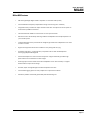
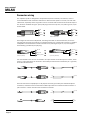
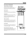
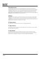
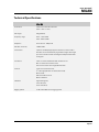
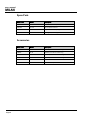
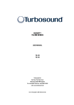
USER GUIDE
Turbosound Ltd
Star Road, Partridge Green
West Sussex RH13 8RY United Kingdom
Tel: +44 (0)1403 711447 Fax: +44 (0)1403 710155
web: www.turbosound.com
Issue 1.0 © Turbosound Ltd
user manual
MILAN
Contents
USER GUIDE ................................................................................................................................................................... 1
Contents .......................................................................................................................................................................... 2
EC Declaration of Conformity .................................................................................................................... 4
Safety considerations ................................................................................................................................ 5
Introduction ................................................................................................................................................ 6
Thanks ......................................................................................................................................................................... 6
Unpacking .................................................................................................................................................................. 6
Contents ................................................................................................................................................................. 6
Getting Started ........................................................................................................................................... 7
Self-Powered Loudspeakers ..................................................................................................................... 8
Signal Flow Block Diagram ..................................................................................................................................... 8
Bass Mode .................................................................................................................................................. 9
Using Milan with Subwoofers ............................................................................................................................ 9
Using Milan as a Floor Monitor .......................................................................................................................... 9
Model Information .................................................................................................................................... 10
Milan MI5 Self-Powered Loudspeaker ........................................................................................................... 10
Milan MI5 Features ............................................................................................................................................ 11
Connector wiring ...................................................................................................................................... 12
Connecting to the Milan MI5 ................................................................................................................... 13
1. Mains Connector and Fuseholder ............................................................................................................... 13
2. Mains Switch ................................................................................................................................................... 13
3. Signal Input ...................................................................................................................................................... 13
4. Mic / Line Switch ............................................................................................................................................ 13
5. Level Control .................................................................................................................................................... 13
6. Bass Control and 7. Treble control .............................................................................................................. 13
8. Bass Mode switch .......................................................................................................................................... 14
9. Mix Out ............................................................................................................................................................. 14
10. Power Indicator ............................................................................................................................................ 14
11. Signal Indicator ............................................................................................................................................. 14
12. Limit indicator ................................................................................................................................................ 14
Connection Diagrams .............................................................................................................................. 15
Small band setup using the integrated mixer and Mix Out ......................................................................... 15
Stereo PA with an external mixer .................................................................................................................... 16
Stereo PA with an external mixer and subwoofer(s) ................................................................................... 17
Stereo PA with powered wedge monitors ..................................................................................................... 18
Loudspeaker Placement .......................................................................................................................... 19
Installing the Milan loudspeaker ............................................................................................................ 20
Using the M10 rigging points ............................................................................................................................ 20
Wall Mounting ..................................................................................................................................................... 20
Troubleshooting ....................................................................................................................................... 21
Product Dimensions ................................................................................................................................. 22
Milan MI5 ............................................................................................................................................................. 22
Technical Specifications ......................................................................................................................... 23
MILAN user manual
Page 2
user manual
MILAN
Spare Parts ................................................................................................................................................ 24
Accessories ............................................................................................................................................................ 24
Warranty .................................................................................................................................................... 25
Contact Information .................................................................................................................................. 26
Customer Service ................................................................................................................................................... 26
Product Information ............................................................................................................................................... 26
Notes .......................................................................................................................................................... 27
MILAN user manual
Page 3
user manual
MILAN
EC Declaration of Conformity
Manufacturer
Turbosound Ltd, Star Road, Partridge Green, West Sussex, RH13 8RY, UK
tel: +44 (0)1403 711447 fax: +44 (0)1403 710155 www.turbosound.com
Products:
Milan MI5
Standards:
Relevant Specifications used as basis for tests
EN55103-1:1996
Directive 1999/5/EC
Category
Professional apparatus for use in Commercial Light Industrial and controlled EMC environments.
CE Marking
All products are marked in accordance with the relevant statutory requirements.
Signatories
Simon Blackwood (Managing Director)
Dominic Harter (Sales Director)
July 2009
MILAN user manual
Page 4
user manual
MILAN
Safety considerations
Before using your Milan loudspeaker please read the following information as it pertains to your
safety and the reliability of your product.
1.
Read and retain these instructions.
2.
Heed all warnings.
3.
Follow all instructions.
4.
Do not use this product near water.
5.
Do not install near any heat sources such as radiators, stoves, boilers, or other apparatus
that produces heat.
6.
Do not allow the mains cable to become damaged, twisted, cut or caught under other
equipment.
7.
Do not use the loudspeaker with AC mains supplies lower than 100v or higher than 240v,
as damage may result.
8.
Use only accessories and attachments approved by the manufacturer. If the product is to
be permanently installed use only rigging hardware approved by Turbosound.
9.
Unplug the loudspeaker during lightning storms or when it is not to be used for long
periods of time.
10. This equipment must be grounded (earthed).
11. Be careful when lifting the loudspeaker, for instance when placing onto speaker stands or
poles. Make sure that you are lifting within your personal capability.
12. Keep the exterior of the loudspeaker enclosure clean, and clean only with a dry cloth.
13. Do not install the loudspeaker in outdoor environments where the product could be
subjected to moisture, excessive temperatures or prolonged UV light exposure.
Electrically powered devices such as this product can present dangerous shock hazards
when wet or exposed to moisture.
14. This product is not suitable for fixed installation in outdoor environments.
MILAN user manual
Page 5
user manual
MILAN
Introduction
Congratulations, you have purchased a professional loudspeaker product from the Milan series of
loudspeakers, designed to give you the best in audio quality and many years of reliable, troublefree operation. It offers excellent pattern control, safe and practical rigging hardware, superior
audio quality, proven reliability, ease of setup, consistent performance, and the backing of a world
leader in acoustics technology including a comprehensive warranty against manufacturing
defects. Please read through this manual carefully before you attempt to operate the loudspeaker
system. It contains valuable information which will enable you to quickly and easily connect the
loudspeakers to your outboard equipment; and important system and set-up checks.
Thanks
Thank you for choosing a TURBOSOUND loudspeaker product for your application.
By engaging in an on-going rigorous program of research and development all TURBOSOUND
products are carefully engineered for world class performance and reliability.
If you would like further information about this or any other TURBOSOUND product, please
contact us. Detailed product information is available on our website at: www.turbosound.com
We look forward to helping you in the near future.
Unpacking
After unpacking the unit please check carefully for damage. If damage is found, please notify the
carrier concerned at once. You, the consignee, must instigate any claim. Please retain all
packaging in case of future re-shipment.
Contents
Milan MI5 loudspeaker
IEC mains cable
User Guide
Turbosound logo sticker
MILAN user manual
Page 6
user manual
MILAN
Getting Started
BASS
TREBLE
0
0
MIX OUT
BASS
MODE
A B
_
+
LEVEL
MIN
MIC
_
+
INPUT 1
MAX
LINE
LIMIT
-6dB
POWER
INPUT 2
LEVEL
MIN
LINE
MAX
MIC
1.
Turn the level controls fully anticlockwise (MIN) on both input channels.
2.
Set the Bass and Treble tone controls to their centre position (no boost or cut).
3.
Connect your signal sources (mixing console, keyboard, microphone, acoustic guitar) to
the input connectors and select MIC or LINE as appropriate for that source.
4.
If the loudspeaker is to be used as a floor monitor, or for use with subwoofers, set the
BASS MODE switch to the ‘B’ position; otherwise select the ‘A’ position.
5.
Switch on the mixer or other source and make sure the output faders or master output
level controls are turned fully down.
6.
Connect the AC mains cable to the Milan loudspeaker and turn on the mains switch. The
blue POWER LED will illuminate to indicate that mains power is connected.
7.
Increase the output level of the signal source to a normal operating level.
8.
Slowly turn up the Milan loudspeaker’s level control(s) until a suitable volume level is
reached. The green SIGNAL LED illuminates when the input signal is -6dB from limiting.
It is normal for the LIMIT LED to flash occasionally, but excessive or prolonged
illumination indicates that the input signal is too high or additional speakers are required.
9.
When shutting down the Milan system, first turn down the input level controls, then
switch off the mains power before turning off the mixer or signal source.
MILAN user manual
Page 7
user manual
MILAN
Self-Powered Loudspeakers
Milan series self-powered loudspeakers are equipped with an integrated Class D amplifier module,
taking consistent performance, convenience and ease of use to a new level. Featuring lightweight
high-power amplifiers using 48kHz DSP and operating at better than 90% efficiency, Milan
eliminates the need for separate amplifier racks and controllers, as well as the attendant cabling.
This makes setting up at gigs and obtaining a consistent sound in different venues a faster and
simpler process.
The amplifier is exactly matched to the known parameters of the loudspeaker components, and is
therefore able to produce the optimum power for the drivers. By placing the amplifier in the
cabinet it is possible to keep the loudspeaker cables extremely short to eliminate resistive losses,
so effectively all the power from the amplifier is transferred to the drivers.
The availability of on-board electronics provides an opportunity to build in a two-channel mixer
offering both mic and line inputs with two band EQ and sophisticated DSP-based limiting. These
fast-acting, frequency-dependent limiters allow you to achieve higher average sound pressure
level, reduce the possibility of driver damage, and help to ensure better long-term system
reliability.
A professional quality crossover network filters the low and high frequencies appropriately to each
driver, to ensure that each is working in its optimum frequency band. The high-grade circuit
components ensure that every loudspeaker performs consistently.
Due to the extremely high efficiency and modern, high performance power supply, the Milan
amplifier module only adds less than 2 kilos to the overall net weight of the loudspeaker, and this
is an important factor in portable applications where the loudspeaker is to be transported and set
up frequently in a variety of venues.
Signal Flow Block Diagram
BASS
MODE
USER EQ
MIC +24.6dB
LINE -3.5dB
LEVEL
TO 20dB
TREBLE
BASS
JACK
CHANNEL 1
XLR
2
1
VOICED
HIGH PASS
3
+
JACK
BASS
1
3
LEVEL
TO 20dB
AMPLIFIER
3
2
MIC +24.6dB
LINE -3.5dB
MILAN user manual
Page 8
DYNAMIC
PROTECTION
LEVEL
DETECT
CHANNEL 2
XLR
TREBLE
PARAMETRIC
EQ
-6dB
CLIP/LIMIT
2
1
MIX OUT
user manual
MILAN
Bass Mode
The BASS MODE switch introduces a 100Hz filter in the bass part of the frequency response. In the
‘B’ position it allows better integration of sub-bass loudspeakers with Milan MI5 loudspeakers by
preventing an overlap in the bass frequencies. The subjective result is extended bass response.
If you are using Milan without subwoofers we recommend that you select the ‘A’ position, which
will ensure the frequency response is unaffected.
Using Milan with Subwoofers
Improved bass response and higher overall sound pressure level can be achieved by adding subbass loudspeakers to the Milan system. This also reduces mechanical stress on the Milan
loudspeaker’s low frequency driver, since most of the low frequency content in the signal is routed
to the subwoofer.
It is recommended that you connect the full range signal from the mixer
first to the subwoofer(s), and from there to the Milan MI5. Make sure the
BASS MODE switch is correctly selected to the ‘B’ position.
When using non-powered subwoofers, take a separate output from the
mixer and run it to the sub-frequency amplifier(s). Connect directly from the
mixer outputs to the Milan loudspeaker as in the example without
subwoofers, but select the ‘B’ position on the BASS MODE switch to allow
the majority of low frequencies to be handled by the subwoofers.
Using Milan as a Floor Monitor
You can select the ‘B’ position on the BASS MODE switch when using Milan
as a floor monitor, which will avoid any low frequency boominess due to
the proximity of the floor that can detract from clear and intelligible monitor
sound.
If you are using Milan as part of a larger multi-channel monitor system and
where drums may be part of the monitor mix, BASS MODE ‘A’ can be
selected provided that kick drum EQ is used sparingly and carefully.
MILAN user manual
Page 9
user manual
MILAN
Model Information
Milan MI5 Self-Powered Loudspeaker
The Milan MI5 is a self-powered sound reinforcement
loudspeaker designed for many different portable and
permanently installed applications.
It consists of a 450 watt program 15” neodymium low
frequency driver, matched with a 1” neodymium high
frequency compression driver on a 90° horizontal x 60°
vertical horn, together with a Class D amplifier module
providing two input channels and on-board DSP.
The low frequency driver is a custom-designed 15” unit
using a 2.5” voice coil driven by a neodymium ring
magnet. The custom-developed 1” exit HF compression
driver feeds a wide dispersion Converging Elliptical
Waveguide for smooth and even coverage over a wide
audience area.
These high quality professional components are
housed in a lightweight, stylish and durable trapezoidal
moulded polypropylene cabinet that is instantly
adaptable to front-of-house or floor monitoring
applications. The cabinet is extensively ribbed and
internally damped. This design feature increases the
cabinet’s rigidity and eliminates internal reflections, which translates into better transient
response and improved bass reproduction. It also keeps the weight of the cabinet as low as
possible.
Milan is equipped with a dual angle pole mount socket which allows it to be angled down for
better coverage when used with tripod stands or for mounting on top of bass cabinets. Lifting and
carrying is made easy with the provision of built-in handles on the sides, as well as a scoop handle
on the top of the cabinet.
The Milan cabinet provides M10 rigging points on the top and bottom for suspending horizontally
or vertically in permanent installs.
MILAN user manual
Page 10
user manual
MILAN
Milan MI5 Features
•
450 watt lightweight digital Class D amplifier for excellent audio quality
•
Internal DSP with frequency-dependent limiting ensures long term reliability
•
Integrated mixer provides two input channels each with microphone and line inputs via
combination jack/XLR connectors
•
Two-band EQ with 12dB of cut and boost on both input channels
•
Mix Out function allows daisy-chaining of Milan loudspeakers and simple expansion of
your sound system
•
Trapezoidal shape with symmetrical 43° wedge angle allows the loudspeaker to be used
as a floor monitor
•
Ergonomically placed aluminium handles for easy lifting and carrying
•
Professional quality 1” high frequency compression driver with wide dispersion
Converging Elliptical Waveguide
•
Custom developed 15” LF driver with neodymium magnet assembly provides high
performance and contributes to lower weight
•
Dual angle pole mount socket allows the loudspeaker to be used vertically or angled
downwards for improved coverage
•
Durable, stylish and lightweight moulded composite enclosure
•
Internal M10 rigging points for easy suspension in permanent installs
•
Attractive powder coated and galvanised perforated steel grille
MILAN user manual
Page 11
user manual
MILAN
Connector wiring
The amplifier inputs are designed to accept balanced (three conductor) connections, and it is
recommended that this method be used since it offers the best rejection of noise, hum and radio
interference, especially where long cable runs are involved. XLR connectors should be wired pin 2
hot, while the standard wiring for 3-pole jack plug connectors is tip hot (+ve) and ring cold (-ve) as
shown below.
hot
ground
cold
cold
ground
Balanced male XLR
hot
Balanced female XLR
Some signal sources such as keyboards, acoustic guitars with on-board electronics, and some
microphones commonly provide only an unbalanced output on a 2-pole jack connector. The Milan
loudspeaker can handle these connections without any rewiring since pin 3 (-ve) of the input is
automatically grounded by the jack plug.
3-pole jack (balanced)
tip - hot
tip - hot
ring - cold
cold
sleeve - ground
ground
2-pole Jack (unbalanced)
If an unbalanced source is to be connected to an input channel via the XLR input connector, either
2-pole or 3-pole jack plugs can be used. In both cases pin 3 should be connected to pin 1 (ground)
at the XLR as shown here.
tip
ring
sleeve
1 (ground)
2
3
tip
1 (ground)
2
3
sleeve
Some sources such as mp3 players or CD players commonly provide 2-pole unbalanced phono
connectors, and these can be connected to a Milan input channel via either the XLR connector or
jack connector. In either case wire the connectors as follows:
tip
sleeve
tip
sleeve
MILAN user manual
Page 12
1 (ground)
2
3
tip
sleeve
user manual
MILAN
Connecting to the Milan MI5
6
7
8
BASS
TREBLE
MIX OUT
1. Mains Connector and Fuseholder
9
Mains power is connected to the loudspeaker via a
combination IEC connector and fuseholder. The power supply
is auto-sensing and can be connected to mains supplies
0
0
A B
change any settings.
_
_
+
LEVEL
2. Mains Switch
LIMIT
BASS
MODE
ranging from 110 volts to 240 volts AC without the need to
-6dB
+
INPUT 1
POWER
INPUT 2
LEVEL
5
Rocker switch turns mains power on to the loudspeaker. Make
5
MIN
sure the level controls are fully off (MIN) before switching on.
MAX
MIC
MIN
LINE
MAX
LINE
MIC
3. Signal Input
These combo female XLR/jack connectors accept both XLR
connectors and mono (2 pole) or stereo (3 pole) ¼” jack plugs
4
for use with a variety of balanced and unbalanced
3
3
4
microphones, instruments and line sources. The inputs are
balanced to avoid hum loops and RF interference, and are
wired pin 2 hot, pin 3 cold.
4. Mic / Line Switch
Selects the input for that channel to accept either a low level,
low impedance microphone, or a high level, high impedance
source such as a mixing console, keyboard or acoustic
instrument with onboard electrics. The mic input is not suitable
for condenser microphones that require phantom power.
5. Level Control
Rotary level control which attenuates the input signal level of
the connected instrument / line source for that input channel.
The range (mic) is from -∞ (MIN) to +16.5dB (MAX) and (line)
from -∞ (MIN) to +40.6dB (MAX).
1
The bass control provides ±12dB of shelving at 200Hz, and the
treble control provides ±12dB of shelving at 4kHz. Always use
100-230V
6. Bass Control and 7. Treble control
450Wmax 50-60Hz
POWER
2
ON
FUSE T10AL
REPLACE ON LY WITH SAME
TYPE AND R ATING OF FUSE
equalisation sparingly, aiming to cut rather than boost
especially when the loudspeaker is used near boundaries such
as walls or floors.
MILAN user manual
Page 13
user manual
MILAN
8. Bass Mode switch
This slide switch introduces a fourth order high-pass filter in the lower part of the frequency
response at 100Hz, and is useful to avoid boominess due to proximity to the floor when the Milan
loudspeaker is used as a floor monitor. The bass mode high-pass should also be selected when
the Milan MI5 is used with sub-bass loudspeakers. This allows bass frequencies to be routed
appropriately to the sub-bass speakers, avoiding an overlap between these and the Milan MI5, and
giving greater clarity and definition to the overall sound.
9. Mix Out
A balanced line level output on a balanced male XLR that connects to additional powered Milan
loudspeakers. This output contains a mix of all connected sources and is post-EQ, although it is
independent of the bass mode switch. Note that adjusting the equalisation will similarly affect any
additional Milan loudspeakers connected from this output.
10. Power Indicator
Illuminates blue to indicate that mains power is connected and powered up.
11. Signal Indicator
Illuminates green when the signal level reaches -6dB, and is a useful indicator of the input signal
approaching the limiter threshold.
12. Limit indicator
Illuminates red when the signal level approaches maximum and the limiters start working.
Frequent and/or continuous lighting of limit LED indicates overdriving. If this occurs reduce the
input level to the loudspeaker or enlarge your system with additional loudspeakers.
MILAN user manual
Page 14
user manual
MILAN
Connection Diagrams
Small band setup using the integrated mixer and Mix Out
The built in two channel mixer allows the simultaneous use of either two low impedance dynamic
microphones, a microphone and line level source, or two line level sources. The line level source
could be an acoustic instrument such as a guitar with either passive or active on-board electrics, a
keyboard, or MP3 player. Connect a dynamic mic directly to either of the combo jack/XLR input
connectors, switch the MIC/LINE switch to MIC and adjust the volume level. Connect line sources
to either of the combo jack/XLR connectors, switch the MIC/LINE switch to LINE and adjust the
volume control. More mics and sources can be connected by using the MIX OUT function to daisychain to additional Milan loudspeakers.
BASS
TREBLE
0
0
MIX OUT
BASS
TREBLE
0
0
MIX OUT
LIMIT
LIMIT
BASS
MODE
A B
+
LEVEL
MIN
MIC
+
INPUT 1
MAX
LINE
BASS
MODE
A B
-6dB
+
POWER
INPUT 2
LEVEL
MIN
LINE
LEVEL
MAX
MIC
MIN
MIC
+
INPUT 1
MAX
LINE
-6dB
POWER
INPUT 2
LEVEL
MIN
LINE
MAX
MIC
MILAN user manual
Page 15
user manual
MILAN
Stereo PA with an external mixer
Two Milan loudspeakers form the left and right elements of a stereo PA setup with all signal
sources connected to an external mixing console. Ensure that the mic/line switch is set to LINE on
both loudspeakers. Set the BASS MODE switch to the ‘A’ position when not using subwoofers.
Bring up the master faders on the mixer, ensuring that the outputs are not clipping, and then
adjust both loudspeakers’ level controls to the desired loudness. For consistent balance and
response set the tone controls to approximately the same positions on both cabinets.
LEFT
BASS
TREBLE
0
0
RIGHT
MIX OUT
BASS
TREBLE
0
0
MIX OUT
LIMIT
LIMIT
BASS
MODE
BASS
MODE
A B
+
LEVEL
MIN
MIC
MILAN user manual
Page 16
+
INPUT 1
MAX
LINE
A B
-6dB
+
POWER
INPUT 2
LEVEL
MIN
LINE
LEVEL
MAX
MIC
MIN
MIC
+
INPUT 1
MAX
LINE
-6dB
POWER
INPUT 2
LEVEL
MIN
LINE
MAX
MIC
user manual
MILAN
Stereo PA with an external mixer and subwoofer(s)
In this example, sub frequencies are routed to a separate subwoofer(s) in order to gain extended
frequency response and higher overall sound level. Connect the mixer output first to the
subwoofers and then loop up to the Milan loudspeakers. Set the MIC/LINE switch to LINE and set
the BASS MODE switch to the ‘B’ position to roll off the low frequencies to the Milan MI5
loudspeakers. The tone controls on both cabinets should be set to the same positions, nominally
flat to begin with. Ensure that the mixer outputs are not clipping, and then adjust both
loudspeakers’ level controls to the desired loudness.
BASS
TREBLE
0
0
MIX OUT
BASS
TREBLE
0
0
MIX OUT
LIMIT
+
LEVEL
MIN
MIC
BASS
MODE
A B
A B
+
INPUT 1
LIMIT
BASS
MODE
-6dB
+
POWER
INPUT 2
MAX
LEVEL
MIN
LINE
LINE
POWERED
SUB-BASS
LEVEL
MAX
MIC
MIN
MIC
+
INPUT 1
-6dB
POWER
INPUT 2
MAX
LEVEL
MIN
LINE
LINE
MAX
MIC
POWERED
SUB-BASS
MILAN user manual
Page 17
user manual
MILAN
Stereo PA with powered wedge monitors
On larger gigs a separate monitor system provides good quality foldback for individual performers
and helps to keep the PA sound less cluttered. Select the BASS MODE ‘A’ or ‘B’ position as
required on the Milan monitors.
LEFT
BASS
TREBLE
0
0
RIGHT
MIX OUT
BASS
TREBLE
0
0
MIX OUT
LIMIT
LIMIT
BASS
MODE
A B
+
LEVEL
MIN
+
INPUT 1
INPUT 2
TREBLE
0
LEVEL
MAX
LINE
0
+
LEVEL
MIN
LINE
BASS
A B
POWER
MAX
MIC
BASS
MODE
-6dB
MIN
INPUT 1
INPUT 2
+
LEVEL
MIN
MIC
+
INPUT 1
MAX
BASS
TREBLE
0
0
LINE
MON1
MILAN user manual
Page 18
MIC
MIX OUT
BASS
LIMIT
MODE
A B
-6dB
+
LEVEL
MIN
LINE
MAX
LINE
LIMIT
POWER
INPUT 2
LEVEL
MIN
LINE
MODE
A B
-6dB
POWER
MAX
MIC
MIX OUT
BASS
+
LEVEL
MAX
MIC
MIN
MIC
+
INPUT 1
-6dB
POWER
INPUT 2
MAX
LEVEL
MIN
LINE
LINE
MON2
MAX
MIC
user manual
MILAN
Loudspeaker Placement
In order to avoid the possibility of feedback locate the loudspeakers in front of your microphones
and do not point microphones directly at the front of a loudspeaker.
When using speaker stands, try to raise the loudspeakers as high as
practically possible (at least higher than the heads of the audience) since
people are very good absorbers of sound,
especially at high frequencies. You also
have the option to point them down using
the alternate angle provided for by the builtin dual angle pole holder. Doing this will
improve the coverage for both near and far
audience members.
SAFETY PRECAUTIONS: make sure that any
speaker stands you use are capable of
taking the weight of the loudspeaker, and
that stands are placed on a flat, level and
stable surface. Make sure that the legs do
not present a trip hazard. Take care when
lifting the speakers on to the stand; ask
someone else to help you if needed.
The same applies to using Milan
loudspeakers mounted on straight poles on
top of bass cabinets or subwoofers.
Adjustable height poles or stands allow you
to fine tune the height of the loudspeakers
to suit your venue.
Do not place your loudspeakers too close to
turntables as this may induce rumble or low
frequency feedback from the tone arms.
Isolate turntables on shock mounts.
Use equalisation sparingly. Start with the bass and treble controls at their neutral position (no
boost or cut). Cut a little bass to tame any boomy frequencies in the room, and add a little treble to
help vocal intelligibility.
Consider adding subwoofers and/or further loudspeakers if the overall sound level or low
frequency response is not enough for the room.
MILAN user manual
Page 19
user manual
MILAN
Installing the Milan loudspeaker
Using the M10 rigging points
The Milan loudspeaker can be permanently installed in a venue,
suspended from eyebolts fitted to the internal M10 rigging points
on the top and bottom of the cabinet. Three possible orientations
are available: vertically upright, or upside down to position the high
frequency driver closer to the audience, or sideways if required.
Insert M10 load-rated shoulder eyebolts
into the threaded rigging points and
tighten. The front rigging points should
take the majority of the load while the rear
rigging point should be used for angling
the cabinet downwards only.
When installing the
cabinet sideways,
pick up from either of
the two front eyebolt
pairs, and bridle the two rear eyebolt points to
provide a single pull-back for adjusting the
downward angle.
Wall Mounting
The Milan loudspeaker can be conveniently wall mounted using the PB-55 pole mount wall
bracket, which simply locates into the pole mount socket in the bottom of the cabinet.
Mount the bracket to the wall using suitable fixings, and locate the loudspeaker onto the pole
mount bracket. Rotate and angle the loudspeaker to optimise coverage and tighten the locking
mechanism to stop the loudspeaker from being inadvertently removed.
MILAN user manual
Page 20
user manual
MILAN
Troubleshooting
Fault
Check
Action
No power to the
Is the mains lead plugged in?
Connect the mains lead
Is the mains outlet live?
Check the mains outlet or
loudspeaker
switch to another outlet
No sound / quiet sound
Is the power switch on?
Press the mains switch
Is the level control turned
Turn the control slowly
down (anti-clockwise)?
clockwise
Is the source sending a signal?
Verify signal at the source
output. Un-mute muted
outputs or mixer channels.
Check cables and/or replace
Is the mic/line switch set
Change mic/line setting to
incorrectly?
correct source
No sound from
Is the microphone a
Milan does not supply +48v
connected microphone
condenser type needing
phantom power. Use a
phantom power?
dynamic microphone or
connect to a mixer with
phantom power
No sound although
Is the loudspeaker in protect
Turn off the mains switch,
loudspeaker is on
mode?
unplug the loudspeaker before
reconnecting
Distorted sound
Does the loudspeaker remain
Refer to qualified service
in protect mode?
personnel
Is the input signal level too
Reduce mixer or preamp level
high?
Is the mic/line switch set
Change mic/line setting to
incorrectly?
correct source
Distorted sound, limit
Are the volume controls set
Reduce volume controls or
LED is on continuously
too high?
use additional loudspeakers
Hum or noise
Are the connected sources
Use balanced cables and 3-
balanced?
pole connectors wherever
possible. Check wiring.
Ground loops?
Lift audio ground on affected
device with adapter
Are signal cables near or
Move signal cables
running parallel to mains
cables?
MILAN user manual
Page 21
user manual
MILAN
Product Dimensions
Milan MI5
MILAN user manual
Page 22
user manual
MILAN
Technical Specifications
Milan MI5
Dimensions
720mmH x 470mmW x 400mmD
(28.3” x 18.5” x 15.7”)
Net weight
22kg (48.4lbs)
Frequency range
36Hz – 17kHz ±3dB
23Hz – 22kHz ±10dB
Dispersion
90°H x 60°V @ -6dB points
Max SPL (cont/max)
125dB/131dB
Construction
Injection-moulded polypropylene enclosure, self-coloured in
dark blue. Three recessed carrying handles. Integral dual-angle
pole mount socket. Powder coated galvanised perforated steel
mesh grille
Connectors
Input: 2 x combo jack/female XLR, wired pin 2 hot
Mix out: XLR male, wired pin 2 hot
IEC mains conector with integrated fuseholder
Controls
Level control (each channel)
4th order high-pass filter at 100Hz (bass mode)
Mains on/off
Bass and treble controls
Mic/line switches
Indicators
Signal LED (green)
Limit LED (red)
Power LED (blue)
Rigging options
6 x M10 threaded internal rigging points
MILAN user manual
Page 23
user manual
MILAN
Spare Parts
Stock Code
Model
Description
LS1530
LS-1530
15” (381mm) low frequency driver
04A9330
CD-118
HF compression driver
05B9320
RD-116/118
Replacement HF diaphragm
07A090
MG-MI5
Metal grille (with badge)
Stock Code
Model
Description
07B508/0.6
PA-60
Speaker pole 35mm x 60cm long
07B508
PA-90
Speaker pole 35mm x 90cm long
07B508/1.0
PA-100
Speaker pole 35mm x 100cm long
07B508/1.2
PA-120
Speaker pole 35mm x 120cm long
07B830
PB-55
Pole mount wall bracket
07B392
EB-10/18
M10 shoulder eyebolt
Accessories
MILAN user manual
Page 24
user manual
MILAN
Warranty
All products in this manual are warranted by Turbosound Limited to the original end-user
purchaser against defects in workmanship and materials used in its manufacture for a period of
two (2) years from the date of shipment to the end user.
Faults arising from misuse, unauthorised modifications or accidents are not covered by this
warranty. No other warranty is expressed or implied.
This warranty does not affect any statutory rights of the purchaser.
Should any fault develop with a component of your Turbosound system the faulty unit should be
sent, in its original packaging, to the supplier or your local authorised Turbosound dealer with the
shipping prepaid.
You should include a written statement listing the faults found, and the product serial number
must be quoted ion all correspondence relating to the claim.
IMPORTANT: We recommend you record your purchase information here for future reference.
Dealers Name: ..............................................................................................................................................
Address: ........................................................................................................................................................
........................................................................................................................................................................
........................................................................................................................................................................
Phone No: .....................................................................................................................................................
Invoice/Receipt No./Date . ...........................................................................................................................
Serial number: ..............................................................................................................................................
........................................................................................................................................................................
........................................................................................................................................................................
In keeping with our policy of continual improvement, Turbosound Limited reserves the right to
alter specifications without prior notice.
MILAN user manual
Page 25
user manual
MILAN
Contact Information
Turbosound Ltd
Star Road
Partridge Green
West Sussex RH13 8RY
United Kingdom
Customer Service
If your product requires servicing please contact your local distributor or retailer. A complete list is
available on our website at:
www.turbosound.com/distrib/distribs.php
Product Information
You can find full details on all our products on the internet at:
www.turbosound.com/products
MILAN user manual
Page 26
user manual
MILAN
Notes
MILAN user manual
Page 27
user manual
MILAN
MILAN user manual
Page 28