1
ASPECT TA-880 SYSTEM
USER MANUAL
Turbosound Ltd.
Star Road, Partridge Green
West Sussex RH13 8RY England
Tel: +44 (0)1403 711447 Fax: +44 (0)1403 710155
web: www.turbosound.com
Issue 1.5 © Turbosound Ltd, January 2006
user manual
TA-880
Contents
EC Declaration of Conformity........................................................................................................................ 6
Introduction .................................................................................................................................................... 7
Turbosound Aspect System Concepts ..................................................................................................... 7
The Aspect Polyhorn™ Concept............................................................................................................... 8
Aspect TA-880 Turnkey System Concept ................................................................................................. 9
The Loudspeaker Management System (LMS) Concept....................................................................... 10
LMS-D26/D6 Loudspeaker Management Systems ................................................................................ 10
Amplifier Racks........................................................................................................................................ 10
Power Amplifiers..................................................................................................................................... 11
Digital Controllers ................................................................................................................................... 11
Aspect Loudspeaker Components.......................................................................................................... 11
TA-880L Low Frequency Enclosure ........................................................................................................ 12
TSW-218 Subwoofer ............................................................................................................................... 12
TA-880H Mid/High Enclosure.................................................................................................................. 12
TA-880HM High-Mid Enclosure .............................................................................................................. 13
TA-880LM Low-Mid Enclosure................................................................................................................ 13
Transportation ......................................................................................................................................... 14
Aspect trapezoidal Flying System .......................................................................................................... 15
Flying and Stacking...................................................................................................................................... 16
Overview.................................................................................................................................................. 16
GigMate™ Acoustic Simulation .................................................................................................................. 17
Running Turbosound GigMate / EASE Focus for the first time: ........................................................... 17
System Setup .......................................................................................................................................... 18
Mapping Properties................................................................................................................................. 18
Audience Area ......................................................................................................................................... 18
Rigging..................................................................................................................................................... 18
Designing a system ................................................................................................................................. 19
Safety Notes on Rigging ......................................................................................................................... 23
Flying Hardware ........................................................................................................................................... 25
TA-880 user manual
Page 2
user manual
TA-880
Horizontal Coverage................................................................................................................................ 25
Vertical Coverage .................................................................................................................................... 26
Wide and Narrow Flybar settings........................................................................................................... 26
Two-wide trapezoidal flybar FB-880/2W ................................................................................................ 27
Three-wide trapezoidal flybar FB-880/3W.............................................................................................. 28
Flying Chains ........................................................................................................................................... 29
Flying Swords.......................................................................................................................................... 30
Tilting Strap ............................................................................................................................................. 31
Flying a single TA-880 trapezoidal cabinet using M10 eyebolts........................................................... 32
Flying a single TA-880 trapezoidal cabinet using FC-880 chains.......................................................... 33
Flying a vertical column of TA-880 trapezoidal cabinets ...................................................................... 34
Flying a cluster of TA-880 trapezoidal cabinets..................................................................................... 37
Single horizontal row.............................................................................................................................. 37
2 wide x 2 deep TA-880H array............................................................................................................... 38
3 wide x 3 deep TA-880H array............................................................................................................... 39
Tight-packed Flying Assemblies............................................................................................................. 40
Bass Enclosure arraying.......................................................................................................................... 42
Aiming - directivity of the stack.............................................................................................................. 42
Ground stacking ...................................................................................................................................... 43
LMS series Loudspeaker Management Systems ....................................................................................... 44
Introduction ............................................................................................................................................. 44
Unpacking ................................................................................................................................................ 44
Mechanical Installation ........................................................................................................................... 44
LMS-D6 Loudspeaker Management System .............................................................................................. 45
LMS-D6 Rear Panel Functions ................................................................................................................ 46
Mains Power ............................................................................................................................................ 46
Voltage Settings ...................................................................................................................................... 47
Safety Earthing ........................................................................................................................................ 47
AC Power Fusing ..................................................................................................................................... 47
Powering Up ............................................................................................................................................ 47
Audio Connections .................................................................................................................................. 48
Input and Output Connector Wiring....................................................................................................... 48
Time correction for loudspeaker driver placement ............................................................................... 48
LMS-D24 and D26 Loudspeaker management Systems............................................................................ 49
TA-880 user manual
Page 3
user manual
TA-880
Features ................................................................................................................................................... 49
Front Panel Functions ............................................................................................................................. 50
Rear Panel Functions............................................................................................................................... 52
Operating the LMS-D24 and D26............................................................................................................ 53
Starting up ............................................................................................................................................... 53
Selecting a Factory Preset....................................................................................................................... 53
Creating a Crossover............................................................................................................................... 53
Navigation and Viewing Parameters...................................................................................................... 54
Navigation................................................................................................................................................ 55
Presets...................................................................................................................................................... 56
Preset Recall ............................................................................................................................................ 56
Preset Store ............................................................................................................................................. 57
DSP Processing Layout ........................................................................................................................... 58
Input DSP block diagram ........................................................................................................................ 58
Output DSP block diagram ..................................................................................................................... 58
Stereo / Mono Formats ........................................................................................................................... 58
DSP processing........................................................................................................................................ 59
Input Channels......................................................................................................................................... 59
Parametric Equalisation .......................................................................................................................... 61
High and Low shelving filters ................................................................................................................. 61
Parametric filters ..................................................................................................................................... 61
Output Channels...................................................................................................................................... 62
Gain and Polarity..................................................................................................................................... 62
Delay ........................................................................................................................................................ 62
High and Low Pass Filters....................................................................................................................... 63
Parametric Equalisation .......................................................................................................................... 64
Limiters .................................................................................................................................................... 65
Routing..................................................................................................................................................... 65
Utilities ..................................................................................................................................................... 66
Utility functions ....................................................................................................................................... 66
Rear Panel Functions............................................................................................................................... 67
AMP-890 Aspect System Amplification Rack......................................................................................... 68
Racking, Cables and Connections........................................................................................................... 68
Options..................................................................................................................................................... 69
Input Connections ................................................................................................................................... 69
Figure 1. Amplifier Rack Signal Wiring .................................................................................................. 70
Output Connections ................................................................................................................................ 70
Figure 2. Mid-High Outputs .................................................................................................................... 71
Figure 3. Bass Outputs ............................................................................................................................ 71
Break-out Cables – NL4 bass................................................................................................................... 72
Break-out cables – NL8 mid-high............................................................................................................ 73
Extension Cables ..................................................................................................................................... 73
Mains Connections.................................................................................................................................. 74
T-25 and T-45 High Efficiency Audio Power Amplifiers............................................................................. 75
TA-880 user manual
Page 4
user manual
TA-880
General Features & Facilities .................................................................................................................. 75
Front Panel Functions T-25 ..................................................................................................................... 76
Front Panel Functions T-45 ..................................................................................................................... 77
Mechanical Installation ........................................................................................................................... 78
Mains Power ............................................................................................................................................ 78
Powering Up ............................................................................................................................................ 78
Safety Earthing ........................................................................................................................................ 78
Voltage Setting ........................................................................................................................................ 79
Voltage Range ......................................................................................................................................... 79
Audio Connections & Controls ............................................................................................................... 79
Polarity ..................................................................................................................................................... 80
Input Impedance...................................................................................................................................... 80
Gain and Sensitivity Settings ................................................................................................................. 80
Attenuation & Gain Setting .................................................................................................................... 81
Output Connections ................................................................................................................................ 81
Damping Factor ....................................................................................................................................... 81
Long Speaker Lines ................................................................................................................................. 82
The Cooling System ................................................................................................................................ 82
Appendix A: Technical Specifications......................................................................................................... 83
Appendix B: Warranty.................................................................................................................................. 85
TA-880 user manual
Page 5
user manual
TA-880
EC DECLARATION OF CONFORMITY
Manufacturer
Turbosound Ltd
Star Road, Partridge Green, West Sussex, RH13 8RY
Products
T-25 Power Amplifier
T-45 Power Amplifier
LMS-D6 Controller
LMS-D26 Controller
LMS-D24 Controller
Standards
Safety
EN60065:2003
Relevant Specifications used as basis for tests
EN66103-1:1996
EN55103-2:1996
Category
Professional apparatus for use in Commercial Light Industrial and controlled EMC
environments.
CE Marking
All products are marked in accordance with the relevant statutory requirements.
TA-880 user manual
Page 6
user manual
TA-880
INTRODUCTION
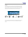
Turbosound Aspect System Concepts
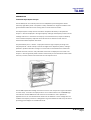
The TA-880 system is a modular point source loudspeaker system designed to deliver
extremely high fidelity audio. The system is easily scaleable from large and medium scale
ground-stacked and flown concert touring down to small clubs and events.
The Aspect system concept centres around the exceptional directivity of the patented
Polyhorn™ devices employed in the high frequency and high-mid frequency sections of the
mid/high enclosure. In contrast to the majority of conventional horns, Polyhorns develop
more consistent frequency response across all seats of an auditorium with minimal
interference between adjacent enclosures.
The patented Polyhorn™ devices – employed in both the high frequency and high-mid
frequency bands – exhibit a sharp cut-off at the edges of the dispersion pattern, making it
possible to produce seamless coverage of a venue with minimal destructive interference
between elements, however many individual enclosures are deployed in the cluster. The
Polyhorn™ devices generate phase-coherent and smoothly-curved wavefronts which match
the array curvature, whose centre becomes the virtual point source.
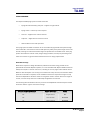
The TA-880H trapezoidal mid/high enclosure forms the main component of ground-stacked
or flown arrays. It can also be employed as a front or side fill cabinet. The TA-880HM highmid enclosure and TA-880LM low-mid enclosure are available for use in specific fill
applications to cover near-field audience areas such as downfills or front-of-stage fills. The
TA-880L low frequency enclosure is designed to be ground stacked in bass arrays as well as
providing ground support for TA-880 enclosures.
TA-880 user manual
Page 7
user manual
TA-880
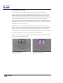
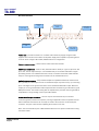
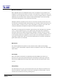
The Aspect Polyhorn™ Concept
The patented Polyhorn™ design effectively solves the problem of the tendency for
exponential horns to beam with increasing frequency. Dividing the multi-cellular horn into
multiple tapered waveguides guarantees that the path length of each micro-horn is equal
from the surface of the driver diaphragm to the horn mouth, and ensures that all frequencies
from all parts of the diaphragm arrive at the horn mouth together. This provides the
wavefront with uniformity of phase. A further benefit of the Polyhorn™ geometry is that the
sound wave does not suffer from edge-diffraction effects which have a tendency to confuse
the directionality of the sound source.
Each cabinet in an array of Aspect loudspeakers contribute to the generation of a single,
cohesive, and more or less continuous wavefront without noticeable comb-filtering effects. In
addition, the Polyhorn™ design offers the possibility of locating the acoustic centre well
behind the motor system and even the enclosure. The wavefront radii can now be arranged
to coincide with the array curvature, forming a single virtual point source.
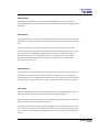
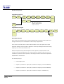
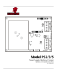
Because of the Polyhorn™ design’s sharp cut-off, its array angle can in practice be taken as
being the same as the dispersion angle.
Fig 1. Conventional HF horns produce
destructive interference
TA-880 user manual
Page 8
Fig 2. Poyhorn™ creates smoothly curved and
phase-coherent wavefront
user manual
TA-880
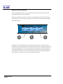
Aspect TA-880 Turnkey System Concept
Aspect is available as an integrated audio system package, comprising loudspeakers with
integral flying hardware, amplifier racks and all necessary drive and control equipment in an
extremely compact and manageable form. In addition, the system has been designed to truck
pack efficiently and handle easily.
The concept of assembling a system around standardised components ensures absolute
compatibility between users, although sufficient flexibility is built into the rack design to
allow for varying requirements such as the ratio of bass cabinets to mid-highs, or 4-way or 5way operation. Aspect systems from different sources may therefore be freely combined
without difficulty. This provides owners with a considerable competitive advantage in
servicing the requirements of international touring productions, and in co-operating with
other Aspect suppliers within the worldwide network.
The system controller functions as an electronic loudspeaker management system,
comprising a 24dB per octave crossover, with factory preset limiters matched to the power
amplifiers, digital time-alignment and electronically balanced inputs and outputs.
The standard trapezoidal Aspect integrated sound system consists of:
•
TA-880H mid-high enclosures and TA-880L enclosures
•
Flybars, flying chains and flybar trunk
•
Loudspeaker break-outs and multi-way extensions
•
Multi-way returns system
•
LMS-D6 or LMS-D26 system controllers
•
AMP-890 ampifier racks with:
•
T-45 and T-25 power amplifiers
•
Three phase 32A power distribution
•
Multi-way and local speaker connections
TA-880 user manual
Page 9
user manual
TA-880
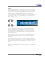
The Loudspeaker Management System (LMS) Concept
Turbosound Loudspeaker Management Systems are more than just electronic crossovers. As
well as steep slope active filters and high performance limiters, they provide full digital
alignment of all components in the Aspect enclosures, to ensure a coherent acoustic output.
They also incorporates a number of features which contribute to overall system reliability
and ease of setting-up and use.
All system parameters such as crossover frequencies, limiter settings and equalisation can be
simply called up from a factory-set menu, making it possible to maintain consistent and
repeatable system performance.
Because the power amplifiers can be included as part of the Aspect system, the controllers
are able to utilise output limiters which are precisely matched to the system requirements,
being pre-set to prevent the amplifiers from clipping. Inputs and outputs are fully balanced,
providing isolation between the controller and the amplifier inputs. These factors contribute
to high reliability in the adverse circumstances often encountered under arduous touring
conditions.
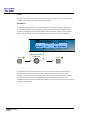
LMS-D26/D6 Loudspeaker Management Systems
Use of the LMS-D26 or LMS-D6 loudspeaker management system ensures accurate timealignment of the system drive units and also provides a facility for users to select additional
delay, either to compensate for physical displacement of ground-stacked bass enclosures
relative to flown high packs, or to provide full range delay for correct image localisation or
use in distributed systems. It should however be noted that the high-Q, and therefore long
throw, properties of the Aspect system generally eliminates the need for distributed delayed
systems, even for very large audiences.
Amplifier Racks
The Aspect amplifier racks are fully loaded and fully equipped for the most demanding
concert touring applications. They are fitted as standard with two T-25 model amplifiers and
three T-45 model amplifiers, Socapex speaker break-outs as well as local connectors, singlephase or three-phase mains distribution, and multi-way signal input and signal link
connectors. All the component parts are rigidly mounted in a 12U steel space frame with
removeable panels, and housed in a road case with heavy duty wheels.
TA-880 user manual
Page 10
user manual
TA-880
Power Amplifiers
In addition to the Turbosound T-25 and T-45 model amplifiers supplied with turnkey Aspect
systems, the following other power amplifier brands provide sufficient performance and
mechanical compatibility to perform well with Aspect loudspeaker systems:
•
MC2 E series
•
Lab Gruppen FP series
•
Crest Pro series
•
QSC Powerlight II series
Digital Controllers
In addition to the Turbosound LMS-D6 and LMS-D26 loudspeaker management systems, the
following digital crossovers have been tested and are recommended for use with Aspect
systems:
•
BSS FDS366
•
XTA 224. 226 and 428
Aspect Loudspeaker Components
All the drive units have been designed in-house specifically for the Aspect system and are
manufactured exclusively for Turbosound. This means that they are expressly suited to their
intended purpose, and make use of innovative features to ensure premium performance.
Neodymium magnets are used throughout all drive units. This results in higher efficiency,
less power compression and reduced overall weight.
Low-mid frequency drivers are designed to be rear-facing in the enclosure, enabling the
heatsink / phase plug to be placed in the air flow to aid cooling.
TA-880 user manual
Page 11
user manual
TA-880
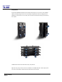
TA-880L Low Frequency Enclosure
The TA-880L low frequency enclosure covers the low
frequency range from 40Hz up to 100Hz. It contains
two very high power 15" neodymium drive units
loaded with TurboBass™ devices. The TA-880L is a
very compact enclosure and its minimal size and low
weight ensures easy handling. It is designed to provide
beneficial low frequency coupling when used in
multiples. The enclosure is designed to be groundstacked.
TSW-218 Subwoofer
The TSW-218 is designed to cover the sub and low
frequency ranges from 25Hz to 160Hz, and can be
used as part of a 5-way Aspect system in order to
reinforce sub-bass frequencies. It utilises two
custom designed neodymium 18” drivers loaded
with TurboBass devices. The proprietary loading
technique and horn flare design produces
significant mutual coupling between adjeacent
enclosures, resulting in sensitivity gains of up to
110dB with eight units coupled.
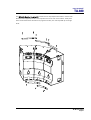
TA-880H Mid/High Enclosure
The TA-880H enclosure covers frequencies above 100Hz
and contains a total of five drive units. A pair of 10”
neodymium low-mid frequency drivers loaded with
TurboMid™ devices covers the frequency range from
100Hz to 400Hz. The low-mid drivers are rear-facing in the
enclosure, providing not only additional cooling by placing
the magnet/heatsink assemblies in the path of the airflow,
but also acting as phase plugs. A specially developed 10”
low-mid driver loaded with a LMF Polyhorn™ device covers
the range from 400Hz to 4kHz. The remaining frequencies
are covered by a pair of 50mm dome drivers loaded with
Polyhorn™ waveguides specifically designed for this
purpose.
The TA-880H Mid-High Enclosure is designed to provide a precise array angle of 25º
horizontal x 15º vertical. This high Q provides the projection necessary for true long throw
applications such as large arena and outdoor productions.
TA-880 user manual
Page 12
user manual
TA-880
The Polyhorn™ and TurboMid™ devices are unique to Turbosound and are covered by
principle patents world-wide. They utilise specialised forms of horn loading which provide
exceptionally low distortion and high efficiency from cone-type drive units. The subjective
effect of these devices is greater clarity and transparency of reproduction when compared
with conventional compression drivers and horns.
The TA-880H can be equipped for touring applications with an external flying system
consisting of removeable swords and fixed angle flybars.
TA-880HM High-Mid Enclosure
The TA-880HM enclosure contains high frequency
and high/mid frequency elements only and is
designed is to be used as a downfill or in-fill
enclosure, either flown or ground-stacked. It covers
the frequency range from 405Hz to 20kHz, and
provides a coverage pattern of 25°H x 15°V.
The TA-880 external flying system of removeable
swords allows all types of TA-880 enclosures to be
combined freely in flown clusters.
TA-880LM Low-Mid Enclosure
The TA-880LM enclosure is a low-mid frequency
only enclosure and is designed is to be used as a
downfill or in-fill enclosure, either flown or groundstacked. It covers the frequency range from 100Hz to
405Hz.
As with the TA-880HM above, it can be combined
into TA-880 clusters using removeable swords.
TA-880 user manual
Page 13
user manual
TA-880
Transportation
An optional WB-880H wheelboard is available which clips on to the front of the TA-880H
cabinet, allowing single units to be conveniently transported. These are designed to be
stackable, so that when not in use they can be neatly stored without taking up unecessary
floor space.
TA-880L bass cabinets are fitted with heavy duty wheels.
Optional heavy duty transit covers are available for TA-880H cabinets. These simply slide
over the box and fasten underneath the cabinet with velcro straps.
TA-880 user manual
Page 14
user manual
TA-880
Aspect trapezoidal Flying System
To take full advantage of the very precise dispersion properties of the Aspect system, an
external rigging system has been developed. The flying systems are inherently safe, flexible
and simple to use. The rigging design allows the creation of clusters and arrays that can be
assembled quickly and with a minimum number of crew, and with full control of the vertical
angles between enclosures and their vertical inclination, to suit a wide variety of
requirements.
TA-880 user manual
Page 15
user manual
TA-880
FLYING AND STACKING
Overview
The Aspect system flying hardware is specifically designed to take advantage of the precise
horizontal directivity characteristics, as well as allow a wide range of adjustment of the
vertical angles between adjacent enclosures, and the overall vertical inclination of each
column of enclosures. This means that arrays can easily be optimised to suit the coverage
requirements of any situation.
Sound radiating from adjacent cabinets will successfully blend over a range of included
angles, creating a coherent point-source image, and this results in the ability to tailor both
the overall coverage and the SPL at a given distance.
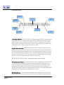
The concept of arraying a point-source loudspeaker system is to create part of the surface of
a sphere. A small part of a large sphere will form a high-directivity (long-throw) system with
a high SPL at a distance, whereas a large part of a small sphere will be of lower directivity
producing less SPL at a distance, but having a wider angle of coverage. This approach leads
to the creation of a virtual point source of sound behind the array.
There are some simple rules to follow to help achieve this goal:
TA-880 user manual
Page 16
•
Obtain a smooth even curve in the horizontal plane.
•
Use a similar amount of tilt on each column.
•
Ensure that the bottom corners of each column are in line with each other.
user manual
TA-880
GIGMATE™ ACOUSTIC SIMULATION
While the Aspect System is remarkably intuitive in terms of building arrays and aiming them,
and requires no theoretical calculations in order to achieve optimum coverage of a room or
audience space due to its inherent ‘point-and-shoot’ nature, there may well be situations
where some prior knowledge of a venue can save time in setting up and configuring the PA.
In order to aid in this process, Turbosound offers the GigMate™ software acoustic simulation
package, a version of the generic EASE Focus program that is based on current EASE 4.1
data.
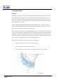
GigMate™ provides an accurate elevation representation of sound pressure level and
coverage of a room, given the dimensions of the audience areas and location of available
rigging points in the venue. The database allows for flown clusters of TA-890 touring or TA880 trapezoidal enclosures, or for ground stacked arrays.
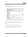
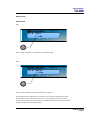
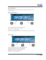
Running Turbosound GigMate / EASE Focus for the first time:
When you first start the program you must set the system file that it is to use. The installation
files include two Turbosound Aspect System files as shown below:
Select the Trapezoidal version of Aspect.
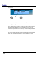
You will now be presented with the GigMate main screen.
TA-880 user manual
Page 17
user manual
TA-880
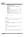
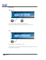
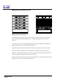
The screen is split into four main areas:
System Setup
The left hand side of the screen is where you define the system, auditorium and project. Tabs
On the bottom of this window allow you to toggle between modes.
Mapping Properties
This is the main window which will display the system as configured in the System Setup
window along with the audience areas and mappings.
Audience Area
Beneath the main Mapping Properties window this graphically displays the SPL on each
audience area, or across a combination of audience areas.
Rigging
The far right window shows the detail of the system configuration and is especially useful in
larger venues where the speakers shown in the main window become very small.
TA-880 user manual
Page 18
user manual
TA-880
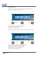
Designing a system
To design a system begin by defining the venue/audience areas by clicking on the “Audience
Area” tab in the bottom left of the screen.
Within this window you can edit or remove existing audience areas, and create new ones.
There are two methods of defining an audience area. In either case you must define the
X1/Y1 coordinate of the start of the area, you can then either enter the X2/Y2 points or its
length and angle.
As you create audience areas they are show graphically in the main window.
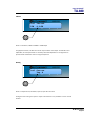
The next step is to design the loudspeaker array using the System Setup window. Select the
System Setup tab in the bottom left of the screen and begin by choosing the desired flybar or
groundstack in the drop down box at the top left of the window.
TA-880 user manual
Page 19
user manual
TA-880
Now select the number of cabinets deep that you wish to hang or stack in the “Box Count”
dropdown. Trim height, or PA wing height can now be set in the “Position” field.
If a mix of Low and High cabinets are to be used then select in the Cabinet window the type
and location in the array of each box. The angle between cabinets can now be set in the
“Angle” list. Each cabinet has an aiming line that can be used to determine the centre of each
cabinet’s dispersion. Adjust the trim height, top angle and intercabinet angle to achieve
optimum coverage.
TA-880 user manual
Page 20
user manual
TA-880
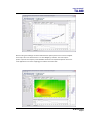
Now that the general design has been established the system performance must be mapped.
At the top of the main window there is an “SPL Mapping” checkbox. This will map the
system output at the frequency and bandwidth selected in the adjacent dropdown boxes. For
most applications a 3 octave mapping gives realistic and useful data.
TA-880 user manual
Page 21
user manual
TA-880
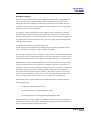
The Audience Area graph at the bottom of the window shows the SPL, as specified in the SPL
Mapping lists, on the selected Audience Area. The selected area is highlighted in the main
window and the graph is repeated onto op each area, Selecting the “Combined Level View”
tab will show the SPL across all areas simultaneously.
Now that the system is mapped the intercabinet angles or row attenuation may be trimmed
to provide the smoothest coverage. Typically the bottom row of the system will require some
attenuation and should be on it’s own “Amp way” to achieve this.
TA-880 user manual
Page 22
user manual
TA-880
Safety Notes on Rigging
The Turbosound TA-880 system has been designed and constructed to a high standard of
safety, and tested to the most demanding of specifications with a safety factor of 13:1.
Always wear protective headwear, footwear and eye protection in accordance with local
regulations. Anyone involved in flying ANY sound system, especially in a touring capacity,
should take note of the following advice:
The rigging of a flown sound system may be dangerous unless undertaken by qualified
personnel with the required experience and certification to perform the necessary tasks.
Fixing of hanging points in a roof should always be carried out by a professional rigger and
in accordance with the local rules of the venue. The house rigger and/or building manager
must always be consulted.
You should observe particularly the following points:
Inspect rigging systems and cabinets for damage before proceeding to assemble a flown
array. If any parts are damaged or suspect, DO NOT USE THEM.
When initially ratcheting a column of speakers it is good to bear in mind the expected angle
of inclination so as to avoid ending up with too much of the strap left on the ratchet. This is
important because the ratchet can only take three complete turns before it releases itself.
WARNING: If a tilt strap is released suddenly, the column of enclosures may tend to swing
violently forwards and care must be taken to avoid danger to persons in the vicinity. It is
essential to check that nobody is standing immediately in front of the column, and to give a
suitable warning, before the strap is released. Ideally, two persons should support the
column from the side whilst the strap is released, or alternatively the bottom row may be
returned to the ground before release. In any event it is essential that all personnel in the
vicinity are aware that the system is about to move and that they must keep clear.
Aspect Flying System components have been individually tested in accordance with the
following regulations:
•
The Health and Safety at Work Act 1974
•
The Supply of Machinery (Safety) Regulations 1992
•
The Lifting Operations and Lifting Equipment Regulations 1998
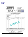
Each component is covered by a Record of Load Test Certificate, which may be obtained on
request from Turbosound, quoting the indentifying number(s) from the flying equipment. A
copy of a sample certificate is reproduced overleaf.
TA-880 user manual
Page 23
user manual
TA-880
Sample Certificate of Load Test
TA-880 user manual
Page 24
user manual
TA-880
FLYING HARDWARE
The Aspect TA-880 flying system consists as follows:
•
Flying swords and safety lynch-pins – support a single cabinet.
•
Flying chains – link the top row to flybars.
•
Twin bar – supports two vertical columns.
•
Triple bar – supports three vertical columns
•
Chain bridles for twin and triple bars
The flying system is based around the use of removeable flying swords which pass through
slots machined in the enclosure and are held captive by safety linch-pins through holes in the
swords, locating into load-rated metal fixings incorporated into the handle boxes. The flying
system eliminates the need for costly integral flying hardware, thereby not penalising those
users who exclusiv ely ground stack and therefore have no flying requirements.
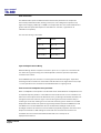
Horizontal Coverage
Because the Polyhorn’s design dramatically reduces the acoustic energy outside of the
specified 25° horizontal dispersion pattern, it is recommended that Aspect TA-880 enclosures
always be arrayed in a smooth even curve, resulting in an array angle of 25° between boxes.
Based on this assumption it is an easy job to assess how many columns, and therefore which
particular combination of flybars, will be needed to achieve the required coverage. The top
chains are adjustable to allow the cluster to hang either close to the bar where trim height is
critical, or further away when more radical kelp is applied to the columns.
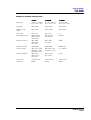
The following table illustrates how many columns of loudspeakers and which flybars should
be used to achieve a given horizontal coverage.
Required Horizontal Coverage
Number of Colums
Flybar
25°
Single column
N/A
50°
Two columns
FB-880/2W
75°
Three columns
FB-880/3W
TA-880 user manual
Page 25
user manual
TA-880
Vertical Coverage
Vertical coverage is dictated by the physical dimensions of the room and the location of the
audience spaces. The number of boxes required in a vertical column is therefore determined
by a number of factors including the trim height of the cluster, the vertical coverage you are
trying to achieve, and the distance or projection required.
Wide and Narrow Flybar settings
The flybars are equipped with two choices of cabinet suspension tabs and tilt strap points for
each column of loudspeakers. These are provided in order to accommodate different
numbers of cabinets in a vertical column. The narrow setting is sufficient when flying
columns up to two deep. However when flying three or four cabinets deep the wide setting with its wider horizontal spacing - allows sufficient downward tilt before the backs of the
lower boxes touch.
TA-880 user manual
Page 26
user manual
TA-880
Two-wide trapezoidal flybar FB-880/2W
TOPVIEW
ENCLOSURE
SUSPENSION
TAB(WIDE)
ENCLOSURE
SUSPENSION
TAB (NARROW)
TILT STRAP
POINTS
BOTTOM VIEW
The FB-880/2W two-wide flybar is a fixed angle double bar designed to fly two vertical
columns of cabinets up to four deep per column. It provides alternative cabinet suspension
tabs and tilt strap points for narrow or wide configurations (when flying more than two boxes
deep the wide configuration allows for the additional amount of kelp required).
The FB-880/2W has a net weight of 18 kgs.
TA-880 user manual
Page 27
user manual
TA-880
Three-wide trapezoidal flybar FB-880/3W
TOPVIEW
ENCLOSURE SUSPENSION
TAB(WIDE)
ENCLOSURE SUSPENSION
TAB (NARROW)
TILTING STRAP
POINT (NARROW)
TILTING STRAP
POINT(WIDE)
BOTTOM VIEW
The FB-880/3W three-wide flybar is a fixed angle triple bar designed to fly three vertical
columns of cabinets up to a total of four deep per column. It provides alternative cabinet
suspension tabs and tilt strap points for regular (up to two cabinets deep) or wide
configurations (when flying more than two boxes deep the wide configuration allows for the
additional amount of kelp required), lifting points and safety points.
The FB-880/3W has a net weight of 21 kgs
TA-880 user manual
Page 28
user manual
TA-880
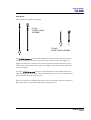
Flying Chains
Flying chains are available in two lengths.
FC-880
CHOKED CHAIN
ASSEMBLY
FC-880S
SHORT CHAIN ASSEMBLY
The FC-880S flying chain is a short chain designed for linking the top row (or single row) of
cabinets to the flybar. It consists of a top hook, chain, connex connector and dagger. The
dagger is provided with a single hole for attachment inside the cabinet’s sword box using a
safety linch pin. Use the short chain to gain more height on the system and also improve the
looks of the cluster.
The longer FC-880 flying chain allows for forward displacement of the speaker cluster and
easier ratcheting when flying three or four cabinets deep with a lot of tilt. It is adjustable, and
can be shorted as required using the choke.
Chains are universal (not handed) and therefore can be used for either side of the cabinet. FC880 flying chains are load tested to 250kg with a safety factor of 4:1.
TA-880 user manual
Page 29
user manual
TA-880
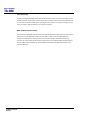
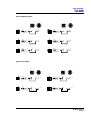
Flying Swords
Three types of flying sword are available:
•
SW-880H swords are used to fly TA-880H mid/high enclosures.
•
SW-880HM swords are used to fly TA-880HM high-mid enclosures.
•
SW-880LM swords are used to fly TA-880LM low-mid enclosures.
SW-880H FLYING SWORD
SW-880HM FLYING SWORD
B
B
A
A
SW-880LM FLYING SWORD
Flying swords are fabricated from steel and are provided with two locating holes at each end,
and these allow for a range of vertical inter-cabinet angles.
TA-880 user manual
Page 30
user manual
TA-880
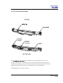
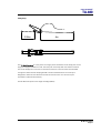
Tilting Strap
0.59m
4m
The TS-890 tilting strap is in two parts. The longer part is attached to the tilt strap point on the
flying bar using the buckle at its end. The other part of the strap with the ratchet is hooked
into the tilt strap point on the rear of the bottom enclosure. The free end is then threaded
through the ratchet and the strap tightened to achieve the desired tilt. The tilt strap is
designed to ratchet in both directions so that the amount of tilt on a column may be
increased or reduced incrementally.
The TS-890 tilt strap has a net weight of 2.5kgs (5.5lbs).
TA-880 user manual
Page 31
user manual
TA-880
Flying a single TA-880 trapezoidal cabinet using M10 eyebolts
The simplest method of flying a TA-880H cabinet is with a pair of M10 shoulder eyebolts on
the top, using a third eyebolt on the rear of the cabinet to tilt the cabinet.
1. Remove the two countersunk M10 screws located just behind the sword slots in the top of
the cabinet.
2. Replace these with M10 shoulder eyebolts with a minimum thread length of 20mm (3/4”)
3. Angle the cabinet as necessary using the third eyebolt position on the rear of the cabinet.
TA-880 user manual
Page 32
user manual
TA-880
Flying a single TA-880 trapezoidal cabinet using FC-880 chains
A single cabinet can be flown using a pair of FC-880S short chains and daggers. These
simply pass through slots in the top of the cabinet and are secured with safety linch-pins
inside the handle boxes. Connect FC-880S short flying chains to the appropriate suspension
tabs on the flybar and check that the daggers line up with the slots. In the diagrams below
only one dagger is shown for clarity.
1. Insert a dagger through the slot machined in the top of the cabinet and into the handle box
as illustrated in the cutaway drawing above. The tip of the dagger located in the sword box
will be visible through the handle hole. Repeat with the second flying chain and dagger.
2. Insert a SL-880 safety linch-pin through the small hole in the dagger from the outside of
the box, and secure it by snapping the safety linch-pin so that it loops around the back of the
dagger. Repeat with the second linch-pin and dagger.
3. When the cabinet is lifted the dagger is held in place by the safety linch-pin, while the slot
allows the cabinet to be freely tilted.
TA-880 user manual
Page 33
user manual
TA-880
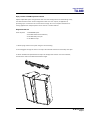
Flying a vertical column of TA-880 trapezoidal cabinets
When flying more than one cabinet deep you will need to use SW-880H swords to suspend
and correctly position the second and subsequent cabinets. These make use of the internal
sword boxes in the trapezoidal cabinet in the same way as the flying chain and dagger, and
ensure that the entire weight of the column is taken through the metalwork and not through
the woodwork of the cabinet. Note that there are two holes in each end of the flying sword;
selection of these determines the vertical angle between cabinets and is explained in the
table and diagrams below.
1. Lift the first cabinet high enough to allow access to the bottom of the cabinet. Insert SW880H flying swords into the cabinet from the bottom, passing them up through the box, and
align them with the lower slots in the sword boxes. You will be able to judge the position of
the sword by looking through the top handle box.
2. Secure the swords on both sides of the cabinet using SL-880 safety linch-pins.
TA-880 user manual
Page 34
user manual
TA-880
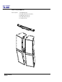
3. Position the second cabinet directly underneath the first. Fit a BS-780 biscuit into the top
kelping braket of the lower cabinet to keep the backs of the boxes and act as the hinge. Lower
the top cabinet and feed the swords into the sword boxes. Make sure that the biscuit engages
into the bottom kelping bracket slot of the upper cabinet. The lower end of the swords will be
visible through the handle boxes of the lower cabinet.
4. Secure them with safety linch-pins on both sides of the cabinet.
Repeat this procedure with any further cabinets required to complete the column of speakers.
TA-880 user manual
Page 35
user manual
TA-880
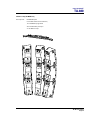
Flying swords are provided with two holes ast each end. This allows for a choice of four
incremental vertical angles depending on which hole the linch-pin is located in, and which
will determine the combined vertical coverage of the column.
Sword hole position
Inter-cabinet angle
A–A
8º
A–B
11º
B–B
15º
A
8°
11°
A
TA-880 user manual
Page 36
B
B
15°
A
B
user manual
TA-880
Flying a cluster of TA-880 trapezoidal cabinets
Aspect trapezoidal flybar configurations offer two basic configurations for assembling arrays,
two-wide and three-wide. These configurations will cover the majority of applications,
providing up to a maximum 75° of horizontal coverage. For more complex installations or
touring applications multiple flybars can be used in a modular fashion.
Single horizontal row
Parts required:
1 x FB-880/2W flybar
4 x FC-880 choked chain assembly
4 x SL-880 safety linch-pin
2 x TS-890 tilt strap
1. Attach flying chains to the flybar using the narrow setting
2. Insert daggers through the slots in the top of the cabinets and secure with safety linch-pins
3. Attach TS-890 tilt straps between the flybar tilt strap points and the rear of the cabinets,
and ratchet to achieve the desired downward angle.
TA-880 user manual
Page 37
user manual
TA-880
2 wide x 2 deep TA-880H array
Parts required:
1 x FB-880/2W flybar
4 x FC-880 choked chain assembly
4 x SW-880H flying sword
4 x SL-880 safety linch-pin
2 x TS-890 tilt strap
TA-880 user manual
Page 38
user manual
TA-880
3 wide x 3 deep TA-880H array
Part required:
FB-880/3W flybar
6 x FC-880 choked chain assembly
12 x SW-880H flying sword
30 x SL-880 safety linch-pin
3 x TS-890 tilt strap
TA-880 user manual
Page 39
user manual
TA-880
Tight-packed Flying Assemblies
When flying single rows of cabinets, especially in installed applications, it is a good idea to
configure the boxes in a tight-packed arrangement in order to achieve high power density in
a small space.
Modular coupling kits are available in two-wide and three-wide configurations in order to
facilitate tight-packed flown clusters. The MC-880/2 Modular Coupling Kit consists of two top
straps which attach to the box with M10 hex bolts (supplied) and a rear strap with fixes to the
rear of the cabinet. These parts when combined hold the cabinets firmly together and they
can now be picked up as a single block.
TA-880 user manual
Page 40
user manual
TA-880
The MC-880/3 Modular Coupling Kit consists of three top straps which attach to the box with
M10 hex bolts (supplied) and two rear strap with fixes to the rear of the cabinet. These parts
when combined hold the cabinets firmly together and they can now be picked up as a single
block.
TA-880 user manual
Page 41
user manual
TA-880
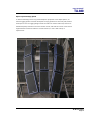
Bass Enclosure arraying
Aspect bass enclosures are most efficient when ground stacked in a block. Not only do they
benefit from improved coupling when there are no air gaps between them, but they also
couple to the ground. However, some of this energy may be absorbed by nearby obstructions
such as barriers or a tightly-packed standing audience. Sound pressure levels may also be
excessive for members of the audience if they are able to get too close to the enclosures.
When stacking on the stage or on a platform, particularly outdoors, it is preferable to close
the gap between the platform and the floor with sheets of plywood. This results in increased
sound projection into the audience and less leakage backstage.
Aiming - directivity of the stack
The directivity of the bass stack will depend on its dimensions and curvature. A tall thin stack
will disperse a lot in the horizontal plane and become narrow in the vertical plane and
likewise a wide stack will narrow in the horizontal plane. There is usually an optimum
compromise between the two so that a smooth transition can be obtained between the effect
of the coupling of the two stacks down the centre line of the room and the effect of the
individual stacks beaming on their axis. Also adding some curvature to the stack will help to
increase the directivity of the stack especially in the higher frequencies.
Tall, thin bass stacks work best, preferably in blocks of six or eight bins high by two wide.
When space permits use two or three of these blocks, placing the onstage block flush with
and parallel to the stage, with a second and additional identical offstage blocks slightly
separated from the first and angled outwards by 40°.
Stacking bass cabinets in a line in front of the stage will produce narrower dispersion in the
horizontal plane, while giving wide vertical dispersion.
TA-880 user manual
Page 42
user manual
TA-880
Ground stacking
In many situations, indoors or outdoors, it is desirable to ground-stack the system. In this
case, the same general rules apply as for flown arrays. High packs should be kept well above
head-height and angled carefully for even coverage. A three-wide stack of TA-880H cabinets
supported by four TA-880L bass cabinets as pictured below provides an ideal configuration
for many situations, giving 75° of horizontal coverage and standing just under 2 metres high.
TA-880 user manual
Page 43
user manual
TA-880
LMS SERIES LOUDSPEAKER MANAGEMENT SYSTEMS
Introduction
This section is provided with the aim of assisting sound engineers, installers and consultants
to fully understand Turbosound Loudspeaker Management Systems, and to obtain the full
benefit of their capabilities.
The LMS-D6, LMS-D26 and LMS-D24 are recommended for use with Aspect loudspeaker
systems, offering varying features and facilities depending on the specific application.
Unpacking
As part of Turbosound's system of quality control, the product is carefully checked before
packing, to ensure flawless appearance. After unpacking the unit, please inspect for any
physical damage. If any damage has occurred, please notify your dealer immediately, so that
a written claim for damages can be initiated. You, the consignee, must instigate any claim.
Please retain all packaging in case of future re-shipment.
There will be a small packet of spare fuses with the unit. Please keep them in a safe place.
Mechanical Installation
A vertical rack space of 1U (44mm / 1.75") is required for each unit. If used in a mobile or
transportable system, the unit must be supported at the rear by additional bracing or
shelving, to prevent vibration-induced metal fatigue of the racking ‘ears’. Failure to do this
will impair reliability and invalidate the Warranty. The rack casing will need a depth of
425mm (minimum) to clear the connectors.
Adequate ventilation must be provided by allowing sufficient room around the sides and rear
of the unit to permit free circulation of air. Forced cooling is not required, a factor which aids
component longevity. The front of the unit should not be exposed to long term direct
sunlight as this can have a detrimental effect on the display lens.
TA-880 user manual
Page 44
user manual
TA-880
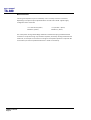
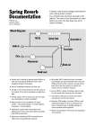
LMS-D6 LOUDSPEAKER MANAGEMENT SYSTEM
5
4
LMS-D6
3
<BACK
NEXT>
MENU
ENTER
6
FREQ
9
'Q'
GAIN
10
A
B
11
1
CLIP
TQ-440
GAIN
8
3
LIM
-3
MUTE -24
-3
MUTE -24
4
5
6
LIM
LIM
LIM
-3
-3
-3
MUTE -24
-24
-24
OUT
DIGITAL LOUDSPEAKER MANAGEMENT SYSTEM
1
2
LIM
-6
-24
BYPASS
12
GAIN
7
GAIN
GAIN
GAIN
GAIN
GAIN
GAIN
2
1.
LCD Display - Shows menu options, output information and adjustment parameters.
2.
Gain Keys - Two input and six-output ‘gain’ keys allow instant access to the gain
screen for each channel. Pressing a second time selects the last function edited.
3.
Next Key - Moves the display forwards through the list of available parameters for
the current input or output channel.
4.
Back Key - Moves the display backwards through the list of available parameters for
the current input or output channel.
5.
Menu Key - Activates the main menu on the LCD display. Pressing a second time
selects the last menu edited. Different menus are selected by pressing the ‘BACK’
and ‘NEXT’ keys or using the ‘FREQ’ control.
6.
Enter Key - Enters the chosen menu and confirms menu selections.
7.
OUT Key - Exits the menu.
8.
Bypass Key - Allows the currently displayed parametric section to be bypassed.
(Note: The Highpass / Lowpass filters and limiters can not be bypassed.)
9.
Parameter Controls - The three velocity sensitive rotary encoders allow the relevant
parameter, on the LCD screen, to be adjusted.
10. Input Meters - Displays available headroom before input clipping occurs. The
bottom green LED is set at -24dB, with the orange 0dB LED set at 3dB below
clipping. The top, red LED displays digital overflow and can therefore light without
all the other LEDs becoming illuminated.
11. Output Meters - Displays headroom before limiting occurs. The bottom green LED is
set at -24dB, with the orange ‘LIM’ LED set at the limiter threshold for that channel.
The top, red LED indicates 4dB of limiting.
12. Mute Keys – One mute key per output channel.
TA-880 user manual
Page 45
user manual
TA-880
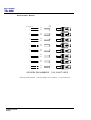
LMS-D6 Rear Panel Functions
RS232
DATA INPUT
WARNING / AVIS
OUTPUT 6
OUTPUT 5
OUTPUT 4
OUTPUT 3
OUTPUT 2
OUTPUT 1
INPUT B
INPUT A
DO NOT EXP OS E TO RA IN OR MOIST URE
THIS EQUIPMENT MUST BE EARTHED
SHOCK HAZARD – DO NOT REMOVE CO VERS
RISQUE DE CHOC ELECTRIQUE - NE PAS OUVRIR
PROTECTION AGAINST FIRE
REPLACE ONLY WITH THE
SAME TYPE T1A, 250V FUSE
1
2
3
PIN1=SHIELD
PIN2=HOT
PIN3=COLD
CUSTOM MADE FOR TURBOSOUND
IN THE UK BY XTA ELECTRONICS
4
5
13. Power Switch.
14. Mains Fuse - Located in a finger-proof fuseholder adjacent to the mains inlet.
Always replace this fuse with the correct type as shown on the rear panel legend.
(N.B. A spare fuse is located in this holder.)
15. Mains Power - Connected via a standard IEC socket. A compatible power cord is
supplied with the unit.
16. External - RS232 via a 9-pin DIN DEE socket, for connection to a PC.
17. XLR Inputs and Outputs - 3 pin XLR connectors are provided for each audio input
and output. All terminations are fully balanced, pin 2 Hot, pin 3 Cold and pin 1 not
connected.
Mains Power
The LMS-D6 must always be connected to a 3 wire grounded AC supply. It is supplied with a
standard IEC power cord with conductors as follows:
BROWN
Power line Live (Phase)
BLUE
Power line Neutral
GREEN/YELLOW
Safety Earth and ground connection
Units supplied to the North American market are fitted with an integral moulded 3 pin
connector, which is provided to satisfy UL & CSA safety standards.
TA-880 user manual
Page 46
user manual
TA-880
Voltage Settings
The LMS-D6 is provided with an auto-seeking power supply, and therefore requires no
external adjustment for correct operation with international AC line voltages ranging from 60
to 250 volts.
Safety Earthing
The green/yellow wire of mains cord must always be connected to the electrical installation's
Safety Earth or Ground. It is essential for personal safety, as well as proper operation of the
unit.
The green/yellow wire is internally connected to all exposed metal surfaces. Any rack
framework which this unit might be mounted into is assumed to be connected to the same
grounding circuit. The LMS-D6 has balanced audio connections and does not require
disconnection of this or any other safety earth for the avoidance of hum loops. If any
problems are experienced with hums or buzzes, careful attention to the signal cable
grounding will effect a cure.
AC Power Fusing
The incoming mains power fuseholder is mounted on the rear panel. If the fuse needs to be
replaced it must be properly rated as follows: 20mm 1A 250 V type T. It is important for
continued safety that this specification is adhered to. It is very unlikely that this fuse will fail
during normal use, and such a situation must be treated with some caution as to the cause.
Powering Up
When the LMS-D6 is switched on by operating the power on-off switch located on the rear
panel, the internal circuitry carries out a series of routine diagnostic tests.
After the switch-on cycle, the screen will revert to displaying the delay program name that
was in use when the unit was last powered down.
The internal memory automatically saves all settings when the unit is switched off, so there
is no need to re-load delay and temperature information every time the system is poweredup. The memory contents are retained indefinitely without the need for an internal backup
battery.
TA-880 user manual
Page 47
user manual
TA-880
Audio Connections
The LMS-D6 audio inputs are RFI filtered and electronically balanced. The outputs are
electronically balanced and fully floating. Overall, the unit is designed to operate at any
signal levels ranging -10dBu up to +20dBu. The outputs will drive into loads of 600 Ohms or
greater and both inputs and outputs are intended to be 'fuss free', regardless of an
installation's complexity.
The connector wiring is as follows:
Input
Output
Pin 1 n/c
Pin 1 n/c
Pin 2 hot (+)
Pin 2 hot (+)
Pin 3 cold (-)
Pin 3 cold (-)
Input and Output Connector Wiring
Balanced Wiring: whether a system is wired to a 'pin 3 hot' or a 'pin 2 hot' convention will
not matter as long as the wiring of hot & cold phases to both the input and output XLR
connectors is the same.
At the LMS-D6 input, the convention is 'screen goes forward with the signal'. Input cable
screening therefore needs to be connected at and derived from the signal source end, as pin
1 on the input XLR is not connected to the LMS-D6 chassis nor signal ground.
Time correction for loudspeaker driver placement
When a loudspeaker sound system is constructed which utilises different loudspeaker drivers
for separate frequency bands, it is inevitable that the sound sources are non-coincident. The
effect of this is that phase and time differences occur, producing a substantial cancellation of
the signal around the crossover region. There is also a general lack of transient clarity or
smearing of the sound, resulting from an inaccurate combining of the wavefront. The LMSD6 provides and maintains the optimum signal delay between the HF and HMF drivers and
the LMF driver in the TFS-780H when the unit is switched to Flashlight mode, and in
Floodlight mode the three drivers in the TFL-760H are physically aligned so inter-driver time
delays are switched out. DSP settings for these and other Turbosound controllers are
availalable from the Turbosound website Downloads area or the ftp site at
ftp://ftp.turbosound.com
TA-880 user manual
Page 48
user manual
TA-880
LMS-D24 AND D26 LOUDSPEAKER MANAGEMENT SYSTEMS
Features
•
Minimal signal path design, providing exceptional audio quality with carefully
optimised processing and high performance converters for a full >111dB dynamic
range, 96kHz sampling rate and minimal filtering. Audio-grade capacitors are used
in the analogue signal path.
•
Sonically superb ADC / DAC combination; a carefully matched pairing of the best
devices from Burr Brown and Wolfson.
•
Newly released family of Analogue Devices SHARC DSP.
•
Extended bandwidth; 96kHz sampling frequency provides for a nominally flat
response to 40kHz.
•
Front panel parameter rotary encoder provides a familiar and easy to use control
format with all filter information displayed simultaneously on a backlit LCD display.
TA-880 user manual
Page 49
user manual
TA-880
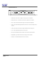
Front Panel Functions
Channel Select
buttons
Store and
Recall buttons
Input Signal
Indicators
2x 24 character
LCD
Limiter
Indicators
Parameter Edit
Encoders
Edit Parameter
Select buttons
Output Mute
buttons
Input Signal Indicators – A set of three pairs of LED’s indicate signal present, +4dBu and input
clip for both channels. The signal present LED’s operate at approximately –40 dBu, giving a
useful indication of even relatively low input signal levels. The +4 dBu LED’s are intended to
show nominal operating level and can also be useful for setting system gain structure. Clip
LED’s warn the user of input overload and operate at +19 dBu.
Program Store and Recall – these controls provide access to 45 presets. Pressing the store
button allows the user to name a preset and choose which memory location it will be held in.
Pressing store button again completes the process. The Recall function operates in a similar
way, pressing the recall button allows the user to select which preset they require, pressing
the button for a second time, then confirming, recalls the new DSP settings. The unit allows
the user to set up user programs with full access to all parameters.
Note that presets cannot be stored or recalled when secure mode is activated.
Channel Selection Buttons – the currently selected channel is displayed on the top left hand
corner of the LCD. Pressing the channel buttons scrolls through the available input and
output channels and finally through the utility functions and back to the default screen. If
operating a stereo-linked preset the channel name will indicate the channel pairing. For
example ‘A+B’ means both input A and B parameters. The name of the output will be shown
briefly at the top of the display when stepping onto an output.
Edit Select Buttons – the currently selected edit parameter is displayed on the bottom left
corner of the LCD. Pressing the edit select buttons moves through the available parameters
TA-880 user manual
Page 50
user manual
TA-880
for the current input or output.
Text display – preset, channel, parameter and status information is shown on the 2x 24character text display. In most screens the currently selected channel is displayed on the
upper line and the edit parameter on the lower line. To simplify the display and enhance
security, some parameters or parameter pages are omitted when not relevant.
Parameter Knobs – three velocity sensitive parameter knobs are used to adjust parameters
shown on the display. Up to three parameters are displayed on the screen. The parameter
name is shown above the parameter value in each of the three screen sections. The
parameter knobs have a fixed association with the screen sections; the rightmost parameter
knob adjusts the rightmost parameter and so on.
Output signal and limiter indication – two LED’s are provided for each output channel. These
show the signal level relative to the limiter threshold. The yellow LED will light when the
signal is 6dB below the threshold and the red warning LED will light when the limiter
threshold is reached.
Mute buttons and status LED’s – each output has a mute button and associated mute status
LED. Pressing the button toggles the mute on and off.
Note that the mute buttons do not function when the Secure Mode is activated.
Secure Button (on the rear) – a momentary button is fitted behind the rear panel, between
the output XLRs and the RS232 port. When activated, this will disable all the front panel
controls so they cannot affect the signal path, making the unit secure against tampering.
When in secure mode, the indicators still operate normally.
Note that the communications port is still active in secure mode.
TA-880 user manual
Page 51
user manual
TA-880
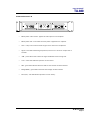
Rear Panel Functions
Expansion
Port
Power Inlet
Secure Mode
Switch
Audio Input
Connectors
Serial Comms
Port
Audio Output
Connectors
Power Inlet – provides connection to a suitable mains electricity supply using the cable
supplied. The controller has a switch mode power supply that is capable of operating with a
nominal mains voltage of 80 to 240v, 50/60Hz without re-configuration.
Network expansion port – where a future network card can be fitted.
Audio Input connectors – these are fully balanced and are wired pin 1 ground, pin 2 hot and
pin 3 cold. The two inputs have pin 1 connected directly to the chassis and feed the signal
processing chains. If an unbalanced source is used, a connection should be made between
the pin 3 ‘cold’ signal and the ground connection of the unbalanced source.
Audio Output connectors – the processed outputs are impedance balanced, and are wired
pin 1 ground, pin 2 hot and pin 3 cold. An unbalanced input may be driven by by connecting
pin 3 ‘cold’ signal to the ground connection of the unbalanced destination input. Note that
output pin-1’s are ground lifted at audio frequencies but connected to ground at RF for good
EMC performance. The intention being that the amplifiers the processor is driving should be
responsible for the grounding of their input cable shields.
Communications port connector – the unit may be controlled entirely from another
controller (typically a Personal Computer), running an application that is compliant with the
ObCom standard. Connection will normally be made to the controller via this serial port
connector. This port is also used for updating the firmware in the unit.
Note: The communications port is NOT disabled when the front panel is made secure using
the secure button.
TA-880 user manual
Page 52
user manual
TA-880
Operating the LMS-D24 and D26
Starting up
The unit will energise as soon as power is applied to the IEC inlet; there is no power switch.
During the start up process the firmware application model number and version numbers are
displayed and the outputs are muted until the unit has completed its internal checks. Once
the start-up routines are complete and the unit is ready to pass audio, the DSP signal path
will be restored to the current settings when it was last powered down and the audio signal
is gradually ramped up to its correct level.
Selecting a Factory Preset
There is a library of thirty Factory Presets to suit a range of Turbosound enclosures.
Factory Presets contain some parameters that are fixed and hidden from view; the remainder
of the DSP parameters are available for user manipulation. The number and type of hidden
parameters is dependant on the Factory Preset, typically crossover frequencies, output delay
and some EQ’s are hidden; those settings that are a function of the loudspeaker cabinet
design and should not require adjustment for different applications.
To recall a Factory Preset for a particular cabinet or system, press Recall and use the left hand
parameter knob A to scroll through the available factory preset locations (as indicated by a
box symbol after the preset number). Once the appropriate preset has been selected press
recall again, at which point you will be asked to confirm the action by pressing recall for a
third time. This is to guard against accidental recall of Presets.
Factory Presets are locked so they cannot be over-written. The user can, however, store an
edited version of a Factory Preset in any free preset location.
Details of all the Factory Presets can be found in Appendix A.
Creating a Crossover
In addition to the Factory Presets the unit has two further ‘Base Presets’; mono and stereo.
These Base Presets are stored in locations 1 and 2 respectively, they can be used to develop
settings for any loudspeaker combination and are recalled in the same way as the Factory
Presets described above. These Presets are also locked but the user can name and store their
own edited versions in any free preset location.
TA-880 user manual
Page 53
user manual
TA-880
Navigation and Viewing Parameters
(Note: The LMS-D26 is shown in all the following screen shots; however the features and
parameters apply equally to the LMS-D24)
Many of the processing elements in each input and output path have features that may be
controlled by the user, such as gain, frequency or limiter threshold. We call these adjustable
features parameters.
LMS-D26
In A Freq
EQ1 100Hz
Width
1.4Q
b
a
a
Gain
0.0dB
b
c
c
A parameter may be adjusted when it is displayed by turning one of the three-parameter
knobs. Each of the three-parameter knobs is associated with a zone on the display. Adjusting
the leftmost parameter knob will change the value of the parameter showing in the leftmost
zone of the display and so on. Turn a knob clockwise to increase the value of a parameter, or
anti-clockwise to decrease it. The knobs are velocity-sensitive so turning a knob rapidly will
cause the action to ‘accelerate’, so the value changes more rapidly.
TA-880 user manual
Page 54
user manual
TA-880
Navigation
The DSP parameters are organised by channel. The currently selected channel is shown in
the top left hand corner of the display. You can navigate between the channels by pressing
the channel buttons. Pressing the channel buttons will scroll through the channels, utilities
and back to the default screen. When using a Preset that is stereo linked, the channel
selection will reflect this. For example ‘1&4’ indicates outputs 1 and 4. When navigating onto
an output channel, the usage of the output, as define in the factory preset, will be shown
briefly at the top of the screen.
CHANNEL
LMS-D26
EDIT
Out1 Freq
EQ1 100Hz
a
Width
1.4Q
b
Gain
0.0dB
c
Pressing the edit navigation buttons gives access to the various pages of parameters
available for each channel. The currently selected page is shown in the bottom left hand
corner of the display, this is omitted on some pages where the function is obvious. The
screen shows up to three (normally related) parameters for a given part of the processing
functions on a given channel.
The edit buttons allow you to scroll, in either direction, through the different processing
pages for a given Channel. When you go past the last page, you will be returned to the
default page.
The channel buttons allow you to scroll, in either direction, through the input and output
channels, whilst trying to maintain the currently viewed processing block. If the channel you
scroll to does not have the currently viewed processing block, the next one will be shown
instead.
NB. When the unit powers-up, the settings will be the same as those when the unit was last
switched off.
TA-880 user manual
Page 55
user manual
TA-880
Presets
The device contains a total of forty-five user and Factory Presets. The user cannot overwrite
the basic mono, basic stereo or Factory Preset programs.
Preset Recall
To select an existing Preset, press the Recall Button so the indicator above it illuminates.
Turn parameter knob A until the required Preset number is shown on the display. Factory
presets are indicated by a box symbol appearing after the preset number. Press the Recall
Button again to activate the Preset. Pressing any other button will cancel the operation.
LMS-D26
Preset Name
Recall 32
My System
a
RECALL
SELECT PRESET
TO RECALL
b
c
RECALL
a
Users can develop their own Preset based on one of the basic or Factory Presets stored
within the device. Once a basic or user Preset has been recalled, a user has complete
freedom to adjust any or all of the parameters. Factory Presets can be used as the basis for
user Presets but they have some parameters that are predefined as a function of the
loudspeaker system. These parameters are ‘hidden’ from the user, as they should be constant
regardless of application.
TA-880 user manual
Page 56
user manual
TA-880
Preset Store
To store the current Preset in a user location, press the Preset Store Button so the indicator
above it illuminates. Turn the first parameter knob until the required Preset location number
is show on the display. A Preset name of up to 12 characters in length can be entered using
parameter knobs B and C. Pressing the Store Button again completes the process and stores
the Preset. As with Preset Recall, pressing any other button cancels the operation.
LMS-D26
Preset Name
Store 32
My System
a
STORE
b
c
SELECT STORE
LOCATION
a
STORE
b
c
NAME PRESET
The user can overwrite non-protected Presets only; if an attempt is made to save a Preset in a
location already occupied by a basic or Factory Preset a ‘LOCKED PRESET’ message is
displayed.
TA-880 user manual
Page 57
user manual
TA-880
DSP Processing Layout
Input DSP block diagram
Input A
Input
LED’s
Input
Gain
Delay
4th Order
HPF
Low
Shelf EQ
Six Band
PEQ
High
Shelf EQ
Routing
SUM
- 6dB
NB. Channel B processing is
identical to Channel A but for
clarity it is not shown
Input B
Output DSP block diagram
Delay
8th Order
HPF
8th Order
LPF
Low
Shelf EQ
Six Band
PEQ
High
Shelf EQ
Output
Gain
Mute
Routing
Metering
Stereo / Mono Formats
There is only one ‘standard’ layout of the processing blocks, but flexible routing and control
linking allows this layout to be adapted to a wide variety of applications.
There are two ‘Formats’, Mono or Stereo. With the Mono format, all outputs have unique
parameter settings, and all outputs are identical in terms of processing functions and routing
capability. This is the most flexible Format.
Stereo format pairs the inputs and outputs for stereo operation, the parameters of each
member of the pair being identical. The routing of inputs to outputs is fixed. This format is
intended for symmetrical stereo operation, eliminating the need to make identical parameter
adjustments for each channel.
The channel pairing is:
TA-880 user manual
Page 58
•
Left and Right Inputs
•
Outputs 1 (routed from L input) and 3 (routed from R input) [1 and 4 for LMS-D26]
•
Outputs 2 (routed from L input) and 4 (routed from R input) [2 and 5 for LMS-D26]
•
Outputs 3 (routed from L input) and 6 (routed from R input) – LMS-D26 only]
Limiter
user manual
TA-880
DSP processing
Input Channels
Gain
LMS-D26
In A
Gain
0.0dB
a
c
b
a
Knob A: Gain, adjustable in 0.2dB steps from –80 dB to +20dB
Delay
LMS-D26
In A
Delay
1.50ms
a
b
c
a
Knob A: Delay, adjustable in variable steps from 0 to 400ms
The delay parameter is adjustable in fine steps at low values; the adjustment becomes
progressively coarser as the value increases. The velocity sensitive Parameter Knobs
therefore provide accurate setting of driver offset delays (typically below 10ms) and rapid
setting of longer system alignment delays.
TA-880 user manual
Page 59
user manual
TA-880
High Pass Filter
LMS-D26
In A Freq
Shape
HPF 20.0Hz LR24
a
a
b
c
b
Knob A: Frequency, out (off), 10.0Hz to 25.6kHz in variable steps
Knob B: high pass filter type
System high pass filtering is provided for the input signal. This is the preferred location for
high pass filtering as it affects all outputs and can therefore improve inter-band phase
relationships. Filter type is selectable from Butterworth, Bessel, Linkwitz-Riley and Hardman.
Filter slopes of up to 4th order or 24dB / octave are provided. Not all filter types are available
in all slopes. For example 18dB / octave Linkwitz-Riley filters do not exist.
The Hardman type filter is always described by its’ order as the filter becomes progressively
steeper rather than following a linear slope so a dB/octave description is not accurate.
TA-880 user manual
Page 60
user manual
TA-880
Parametric Equalisation
Eight sections of equalisation are provided, two shelving filters and six fully variable
parametric sections.
High and Low shelving filters
LMS-D26
In A Freq
EQ1 100Hz
Slope
12dB
c
b
a
a
Gain
0.0dB
b
c
Knob A: Frequency, 10.0Hz to 25.6kHz in variable steps
Knob B: Slope, 6 to 12dB / octave in 1dB steps
Knob C: Gain, +/-15dB in 0.2dB steps
The frequency is specified as point where the filter deviates by 3dB from the gain value.
Parametric filters
LMS-D26
In A Freq
EQ1 100Hz
Width
1.4Q
b
a
a
b
Gain
0.0dB
c
c
Knob A, Centre Frequency, 10.0Hz to 25.6kHz in variable steps
Knob B, Width, display selectable, Q or BW (Bandwidth)
BW adjustable from 0.05 to 5 octaves in variable steps
Q adjustable from 14.2 to 0.2 in variable steps
Knob C, Gain, +/-15dB in 0.2dB steps
TA-880 user manual
Page 61
user manual
TA-880
Output Channels
Gain and Polarity
LMS-D26
Out1 Gain
0.0dB
Pol
Rev
a
a
c
b
b
Knob A: Gain, adjustable in 0.2dB steps from –80 dB to +20dB
Knob B: Polarity, selectable, normal or reversed with reference to other outputs
Delay
LMS-D26
Out1 Delay
1.50ms
a
b
c
a
Knob A: Adjustable in variable steps from 0 to 80ms
As for input delay, velocity sensitive Parameter Knobs provide finer adjustment at low levels
and rapid selection of higher values.
TA-880 user manual
Page 62
user manual
TA-880
High and Low Pass Filters
LMS-D26
Out1 Freq
LPF 2.50k
Shape
LR24
a
a
b
c
b
Knob A: Frequency, <<out, 10.0Hz to 25.6kHz, out>>
Knob B: high pass filter type
Filter type is selectable from Butterworth, Bessel, Linkwitz-Riley and Hardman. Filter slopes of
up to 8th order or 48dB / octave are provided. Not all filter types are available in all slopes.
For example 18dB / octave Linkwitz-Riley filters do not exist.
The Hardman type filter is always described by its’ order as the filter becomes progressively
steeper rather than following a linear slope so a dB/octave description is not accurate.
TA-880 user manual
Page 63
user manual
TA-880
Parametric Equalisation
Eight sections of equalisation are provided in a similar format to the input channel
equalisation; two shelving filters and six parametric.
LMS-D26
Out1 Freq
EQ>- 100Hz
Slope
12dB
a
a
Gain
0.0dB
c
b
b
c
Knob A: Frequency, 10.0Hz to 25.6kHz in variable steps
Knob B: Slope, 6 to 12dB / octave in 1dB steps
Knob C: Gain, +/-15dB in 0.2dB steps
The frequency is specified as point where the filter deviates by 3dB from the gain value.
LMS-D26
Out1 Freq
EQ1 100Hz
Width
1.4Q
a
a
b
b
Knob A, Centre Frequency, 10.0Hz to 25.6kHz in variable steps
Knob B, Width, display selectable, Q or BW (Bandwidth)
BW adjustable from 0.05 to 5 octaves in variable steps
Q adjustable from 14.2 to 0.2 in variable steps
Knob C, Gain, +/-15dB in 0.2dB steps
TA-880 user manual
Page 64
Gain
0.0dB
c
c
user manual
TA-880
Limiters
LMS-D26
Out1 Thresh
LIM 4.0dB
a
c
b
a
Knob A: Threshold, -40dBu to 20dBu in 0.2dB steps
A high performance, low distortion limiter is provided on each output. Threshold is user
adjustable; all other parameters are carefully calculated dependant on configuration to
provide clean and effective control of signal dynamics.
Routing
LMS-D26
Out1 Source
Inp A
a
b
c
a
Knob A: Output source, selectable; Input A, Input B or Sum A+B
Configures the routing from input to output. This function is only available in mono format
Presets.
TA-880 user manual
Page 65
user manual
TA-880
Utilities
Utility functions
Two utility functions are provided to adjust screen contrast and the display units used for
parametric equalisation bandwidth.
The device automatically adjusts for the variations in display contrast as the temperature of
the LCD changes. The screen contrast utility control sets the base contrast of the screen and
also allows optimization for a given viewing angle.
Parametric equalisation width parameters can be displayed in either ‘Q’ or bandwidth,
expressed in octaves.
LMS-D26
Util Screen ParaEQ
100%
BW=Q
a
TA-880 user manual
Page 66
b
c
user manual
TA-880
Rear Panel Functions
Expansion
Port
Power Inlet
Secure Mode
Switch
Audio Input
Connectors
Serial Comms
Port
Audio Output
Connectors
Power Inlet – provides connection to a suitable mains electricity supply using the cable
supplied. The controller has a switch mode power supply that is capable of operating with a
nominal mains voltage of 80 to 240v, 50/60Hz without re-configuration.
Network expansion port – where a future network card can be fitted.
Audio Input connectors – these are fully balanced and are wired pin 1 ground, pin 2 hot and
pin 3 cold. The two inputs have pin 1 connected directly to the chassis and feed the signal
processing chains. If an unbalanced source is used, a connection should be made between
the pin 3 ‘cold’ signal and the ground connection of the unbalanced source.
Audio Output connectors – the processed outputs are impedance balanced, and are wired pin
1 ground, pin 2 hot and pin 3 cold. An unbalanced input may be driven by by connecting pin
3 ‘cold’ signal to the ground connection of the unbalanced destination input. Note that output
pin-1’s are ground lifted at audio frequencies but connected to ground at RF for good EMC
performance. The intention being that the amplifiers the processor is driving should be
responsible for the grounding of their input cable shields.
Communications port connector – the unit may be controlled entirely from another controller
(typically a Personal Computer), running an application that is compliant with the ObCom
standard. Connection will normally be made to the controller via this serial port connector.
This port is also used for updating the firmware in the unit.
Note: The communications port is NOT disabled when the front panel is made secure using
the secure button.
TA-880 user manual
Page 67
user manual
TA-880
AMP-890 Aspect System Amplification Rack
Ch.A
Ch.B
Ch.A
Ch.B
Ch.A
Ch.B
Ch.A
Ch.B
Ch.A
Ch.B
INPUT
OR
LINK
SOCAPEX
SOCAPEX
LOW OUTPUTS
CH 1A
CH 1B
CH 2A
HIGH OUTPU
TS
CH 2B
CH 1
CH 2
Racking, Cables and Connections
The AMP-890 Aspect amplification system comprises a complete amplifier rack, flightcase
and cabling system which is adaptable to the varying requirements of modern concert
touring.
The rack contains a total of five lightweight Turbosound T series amplifiers developed and
designed in England for Turbosound by MC2 Audio Ltd.
Input and output connectors are mounted on a pair of 2U 19" panel at the rear of the rack.
The basic rack itself is a space frame fabricated from rectangular steel sections with all
necessary mounting points welded in. The top and side apertures are fitted with removable
panels to allow easy access to the amplifiers and cabling.
A fully shock mounted road case with four heavy duty castors completes the system, which is
designed to fit four across in a standard width truck.
TA-880 user manual
Page 68
user manual
TA-880
Options
The rack is supplied fitted with five amplifiers as standard.
The two top amplifiers are T-25 models, and power the high frequency and high-mid
frequency sections respectively. Three mid-high cabinets will normally be powered from
each channel, although it is possible to run up to four cabinets for some extreme
applications.
The remaining three amplifiers are all T-45 models and power the low-mid frequency and
low frequency sections. Two of these T-45 are dedicated to powering the low frequency
section, and the rationale behind this is as follows:
The acoustic output and low frequency cut-off of the TA-890L bass cabinets are dependent on
the mutual coupling between enclosures, and on the available amplifier power. With systems
of less than 12 bass cabinets per side it is recommended that the ratio of bass cabinets to
mid-high is 4:3 or higher (depending on program material and musical style). Therefore the
provision of an additional low frequency gives considerable flexibility in the configuration of
bass cabinets in small to medium sized systems without carrying extra, and separate, power
amplifiers. Alternatively it enables the implementation of a five-way system – using
subwoofers for extreme LF energy while complementing the fast, accurate bass response
available from the TA-890L – from only one type of rack.
Separate adjustment of the levels of left and right sides of the rack is possible on all
frequency bands. Furthermore, the returns system includes a fifth way to be used either as a
spare line or in conjunction with TSW-218 for large outdoor systems.
Input Connections
As will be seen from the wiring schedule below, the incoming 11 pin Veam socket is
connected via the mono/stereo linking connector to the adjacent link-out Veam and to the
XLR male cable plugs which connect LF, LMF, HMF and HF feeds to the amplifiers in the rack.
In two-channel mode, the second Veam socket becomes the input connector for the second
channel.
TA-880 user manual
Page 69
user manual
TA-880
Figure 1. Amplifier Rack Signal Wiring
GND
COLD -ve
HIGH
BLUE
H O T +v e
CHANNEL B
GND
COLD -ve
H O T +v e
GND
25 PIN
VDM
{
A
E
K
B
F
L
R
C
G
M
S
W
D
H
N
T
X
J
P
U
Y
Q
V
Z
HI/MID
GREEN
A
E
F
G
C
B
D
H
J
M
L
K
Q
P
N
COLD -ve
LO/MI D
YEL LOW
H O T +v e
GND
COLD -ve
B ASS 1
RED
H O T +v e
GND
COLD -ve
B A SS 2
PURPLE
H O T +v e
}
AMP SIGNAL
INPUT
CHANNEL A
A
E
K
B
F
M
L
R
C
G
S
W
N
T
X
D
H
J
P
U
Y
Q
V
Z
N
P
Q
K
L
M
J
H
D
B
C
G
F
E
A
B A SS 2
H O T +v e
PURPLE
COLD -ve
GND
H O T +v e
B ASS 1
RED
COLD -ve
GND
H O T +v e
LO/MI D
YEL LOW
COLD -ve
GND
HI/MID
H O T +v e
GREEN
COLD -ve
GND
H O T +v e
COLD -ve
GND
HIGH
BLUE
}
AMP SIGNAL
INPUT
Output Connections
The amplifier outputs are wired to two 19-way CEEP (Socapex compatible) output sockets,
rated at 20 Amperes per contact. The Socapex output wiring has been arranged to preclude
accidental connection of the mid-high output to anything other than the TA-890H, and of the
low frequency output to anything other than the TA-890L, preventing any risk of drive-unit
damage.
Two 4 metre fanouts are supplied to take the 19-way cable outputs to the speakers. The low
frequency fanout is fitted with six Speakon NL4FC connectors and the Mid-high fanout is
fitted with four Speakon NL8FC connectors. The cables are colour coded to indicate which
amplifier channels they relate to. Mating connectors are screw-locked, ensuring reliability.
In addition to the Socapex outputs, there are also separate local output connections for
running speaker systems not requiring multicore loudspeaker extension cables, for example
ground stacked systems.
TA-880 user manual
Page 70
user manual
TA-880
Figure 2. Mid-High Outputs
SOCAPEX PIN NO.
CH2
NL8 PIN NO.
SOCAPEX PIN NO.
CH2
CH1
NL4FC
HF+
HF -
01
03
4+
4-
HF+
HF -
CHANNEL 1 HF
CH2
02
04
4+
3-
06
08
3+
3-
13
14
15
16
2+
2-
CHANNEL 2 HF
CH1
CH2
CH1
NL4FC
NL4FC
HM+
HM -
05
07
3+
3-
HM+
HM -
CHANNEL 1 HM
CH2
NL8 PIN NO.
CH1
NL4FC
CHANNEL 2 HM
CH1
CH2
NL4FC
LM+
LM -
09
10
11
12
CH1
NL4FC
2+
2-
LM+
LM -
CHANNEL 1 LM
CHANNEL 2 LM
Figure 3. Bass Outputs
SOCAPEX PIN NO.
CH2
NL4 PIN NO.
SOCAPEX PIN NO.
CH2
CH1
NL4FC
LF+
LF -
01
03
02
04
NL4FC
1+
--
LF+
LF -
CH 1A
CHANNEL 1 BASS A
CH2
CH2
LF+
LF -
CHANNEL 1 BASS B
05
07
06
08
1+
--
CH 2A
13
15
14
16
1+
--
CH 2B
CHANNEL 2 BASS A
CH1
NL4FC
NL4 PIN NO.
CH1
09
11
10
12
CH1
NL4FC
1+
--
CH 1B
LF+
LF -
CHANNEL 2 BASS B
TA-880 user manual
Page 71
user manual
TA-880
Break-out Cables – NL4 bass
NL4
PIN NO.
SOCAPEX PIN N O.
01
LOW+
1+
02
LOW-
1-
03
LOW+
1+
04
LOW-
1-
05
LOW+
1+
06
LOW-
1-
07
LOW+
1+
08
LOW-
1-
09
LOW+
1+
10
LOW-
1-
11
LOW+
1+
12
LOW-
1-
13
LOW+
1+
14
LOW-
1-
15
LOW+
1+
16
LOW-
1-
SOCAPEX PIN NUMBERS 17,18,19 NOT USE D
FANOUTS CAN BE SUPPLIED TO EITHER CONNECT 6 OR 8 CABINETS
TA-880 user manual
Page 72
TO TWO AMPLIFIER S
user manual
TA-880
Break-out cables – NL8 mid-high
NL8
PIN NO.
SOCAPEX PIN NO.
11
NL8
PIN NO.
SOCAPEX PIN NO.
LOW/MID-
1-
15
09
LOW/MID+
1+
07
HIGH/MID-
2-
05
HIGH/MID+
03
01
LOW/MID-
1-
13
LOW/MID+
1+
08
HIGH/MID-
2-
2+
06
HIGH/MID+
2+
HIGH-
3-
04
HIGH-
3-
HIGH+
3+
02
HIGH+
3+
12
LOW/MID-
1-
16
LOW/MID-
1-
10
LOW/MID+
1+
14
LOW/MID+
1+
HIGH/MID-
2-
HIGH/MID-
2-
HIGH/MID+
2+
HIGH/MID+
2+
HIGH-
3-
HIGH-
3-
HIGH+
3+
HIGH+
3+
SOCAPEX PIN NUMBERS17,18,19 NOT USED
Extension Cables
25-way extension cables are available to order in 3, 10, 30, 50 and 100 metre lengths (EX-890)
for flying and/or remote positioning of amplifier racks. These cables utilise 2.5 mm2
conductors for low line resistance and are black in colour to minimise visibility to the
audience.
TA-880 user manual
Page 73
user manual
TA-880
Mains Connections
Incoming mains power may be connected by one of a variety of C Form connectors,
depending on the power system specified when the rack was ordered. Typical supply
configurations are as follows:
110 V star-wired (3 phase)
110 V parallel (1 phase)
220/240 V (3 phase)
220/240 V (1 phase)
The mains power wiring utilises Wago distribution blocks with spring-loaded screwless
connectors. The power wiring may therefore be quickly and easily reconfigured should the
need arise, for example if conversion from single to three phase operation is required. We
recommend you consult a qualified electrician in cases of uncertainty.
TA-880 user manual
Page 74
user manual
TA-880
T-25 AND T-45 HIGH EFFICIENCY AUDIO POWER AMPLIFIERS
General Features & Facilities
The T-25 and T-45 are highly efficient, lightweight, rugged high power amplifiers, with many
original features developed to meet the requirements of modern professional sound
reinforcement, for both touring and fixed installations. They have been designed with audio
quality ranking equal first alongside utility and ruggedness.
The T-25 and T-45 utilise proprietary progressive switching rail output, which enables
extremely high voltage swings and peak power without compromising sonic quality. Fan
speed is automatically varied as required to keep the amplifiers within temperature limits.
Signal limiters are included to protect speakers from clipped signals. The amplifiers include
full DC and short circuit protection to ensure trouble-free service even in harsh environments.
•
Two independently controlled and powered channels.
•
High continuous power, in excess of 1250 watts per channel into 4 ohms (T-25) and
2250 watts per channel into 4 ohms (T-45).
•
-3dB indicators to ensure accurate level monitoring
•
Power reduction control (PRC) allows maximum output level to be set below rated
power output
•
A 10kΩ actively balanced, fully floating input is fitted as standard.
•
Front panel display of output device temperature.
•
High damping factor, >400 below 1kHz.
•
Low noise vari-speed fans for quiet operation.
•
Front-panel accessible filter for improved dust collection.
•
Consistent reliability and easy serviceability through solid, lightweight construction
and modular packaging.
TA-880 user manual
Page 75
user manual
TA-880
Front Panel Functions T-25
Ch. A
Ch.B
•
Mains power rocker switch – applies AC mains power to the amplifier.
•
Mains power LED – illuminates when AC power is applied to the amplifier.
•
Gain – rotary control which allows the gain of the channel to be adjusted.
•
Signal – blue LED indicates signal presence, active from a minimum output level of
10 watts.
TA-880 user manual
Page 76
•
-3dB – yellow LED is active when the signal is 3dB below the limiting level.
•
Limit – amber LED indicates operation of the limiters.
•
PRC – green LED indicates when the PRC for that channel has been selected.
•
Bridge (BRG) – green LED illuminates when bridge mode is selected.
•
Fault (A/P) – red LED indicates protection circuit activity.
user manual
TA-880
Front Panel Functions T-45
Ch. A
Ch.B
•
Mains power rocker switch – applies AC mains power to the amplifier.
•
Mains power LED – illuminates when AC power is applied to the amplifier.
•
Gain – rotary control which allows the gain of the channel to be adjusted.
•
Signal – blue LED indicates signal presence, active from a minimum output level of
10 watts.
•
-3dB – yellow LED is active when the signal is 3dB below the limiting level.
•
Limit – amber LED indicates operation of the limiters.
•
PRC – green LED indicates when the PRC for that channel has been selected.
•
Bridge (BRG) – green LED illuminates when bridge mode is selected.
•
Fault (A/P) – red LED indicates protection circuit activity.
TA-880 user manual
Page 77
user manual
TA-880
Mechanical Installation
When supplied as part of the AMP-890.2 system rack, the amplifiers are pre-installed. If an
amplifier is removed from the rack for any reason, it is important to re-install it correctly. The
amplifiers must be supported at the front and rear, as originally supplied. Failure to support it
adequately may eventually result in vibration-induced metal fatigue of the rack mounting
ears and such damage will not be covered by the warranty.
Adequate ventilation is essential, both at the rear of the rack, the sides, and also at the front.
This should be considered carefully when placing covers around the racks for protection from
inclement weather at outdoor events, or when using blacks to mask them from view. If the
venting is inadequate, the amplifier's temperature metering will display this.
CAUTION: Air emerging from the amplifier's high efficiency heat-exchangers can reach 60°C
to 70°C. To prevent personal injury or fire, please ensure that people and combustible or
flammable materials (e.g. plastic waterproofing, newspaper, clothing, costumes, solvents)
are kept at least 2'/0.6m from the amplifier's exhaust outlets. If venting is inadequate, the hot
air can adversely affect other equipment, and may soften some thermoplastic enclosures. If
using plastic coated cables, take care to dress the leads away from the airflow. Professionalgrade rubber cables are not affected.
Mains Power
The T series amplifiers will operate from any international 50 - 60Hz AC mains supply
between 110-120 V and 220-240 V. Separate models are supplied to match local mains supply
requirements.
Powering Up
When the amplifier is switched on by depressing the black POWER rocker switch, the
protection circuit will initially activate whilst the circuits stabilise. Assuming no faults are
detected the POWER LED (and the signal LED if signal is present) will light up after a fewe
seconds.
Safety Earthing
The Green/Yellow wire on the T-25 and T-45’s mains cord must always be connected to the
electrical installation's safety Earth (or Ground). It is essential for personal safety. The rack
framework is connected to the same grounding circuit.
TA-880 user manual
Page 78
user manual
TA-880
Voltage Setting
Your models will be set up at the factory for correct operation on your local voltage supply.
No further adjustment is necessary.
Voltage Range
The minimum supply voltage over which the amplifier will operate is 180V for the 220-240V
range, and 90V for the 110-120V range. Naturally, maximum power output will be reduced
accordingly from the published ratings.
The maximum supply voltage which exceeds safe limits and causes the amplifiers to switchoff is in excess of 260 V for 220/240 V range, and 130 V for the 108/120 V range. This is
however dependent on load impedance and program drive level as mentioned above.
Obviously, the mains voltage will reach these limits only in exceptional circumstances and
the A/P (Audio Protect) LED will then flash.
Audio Connections & Controls
The amplifiers’ actively balanced, fully-floating input connections are fuss-free, regardless of
the installation's complexity.
The incoming 3-pin XLR plug should be connected, with a high grade twin-core sreened
cable, as follows.
Pin 1
Screen - connect to shield
Pin 2
hot (signal +)
Pin 3
cold (signal -)
The shield connection to pin 1 at each amplifier input must be maintained under all
circumstances, as TURBOSOUND will not be responsible for consequential damage arising to
loudspeakers, etc., should this connection not be made.
TA-880 user manual
Page 79
user manual
TA-880
The amplifiers are designed to operate with fully balanced equipment. Ground loops or loss
of performance may be experienced if connected to unbalanced sources. If it is unavoidable,
however, the following wiring convention should be used.
Pin 1
Screen - connect to chassis of the unbalanced
equipment, or left disconnected at the unbalanced end
Pin 2
signal hot
Pin 3
Signal cold
Polarity
In accordance with international standards, T series amplifiers are supplied with Pin 2 hot (+),
so a positive (+V) input gives a positive (+V) output from the positive (+) output terminals.
Input Impedance
Each amplifier channel has an input impedance of 10kΩ, seen between pins 2 & 3 of the XLR.
When used with the LMS-D6 Loudspeaker Management System, distribution amplifiers are
not required when a large number of T-25 or T-45 amplifier inputs are driven in parallel.
Gain and Sensitivity Settings
Gain settings are changed internally by simple jumper links. Two rows of pins marked - GAIN
A and GAIN B - are situated on the input PCB (PCB701). A jumper link sets the gain and the
settings are as follows:
NOTE:
TA-880 user manual
Page 80
Link 1 & 2
Gives 32dB gain
Link 3 & 4
Gives 26dB gain
Link 2 & 3
Gives approx 37.5dB gain
Factory setting is normally link 1 & 2 = 32dB gain.
user manual
TA-880
Setting higher gain does not change the maximum available power but changes the level of
signal input to achieve maximum power. In any case, provided that the input signal is less
than 20dBu/7.7V, the built in limiter circuit will prevent distortion within the amplifier.
The gain should be set to match the signal from the source, e.g. mixer, controller, or
equaliser.
Attenuation & Gain Setting
The front panel gain controls allow precise level settings, and may be used to adjust the
relative levels of sections of a large system, for example downfills or side seating cover in an
arena.
The front panel gain controls are also useful when initially checking a system after it has
been connected up.
Note that in BRIDGED mode only the Channel A control is active.
Output Connections
A Speakon NL4 connector is provided on each channel.
Damping Factor
The T series amplifier outputs provide a high damping factor, typically 400 times at low audio
frequencies. This damping helps the amplifier to control the loudspeaker drive units,
provided that the resistance of the intervening cables and connectors is very low. The sonic
benefits of high damping factor are most pronounced at bass and low-midrange frequencies
(i.e. 10 to 600Hz) providing a subjectively tighter sound as a result of the improved
reproduction of transients.
Amplifier damping factor is degraded by high resistance in the loudspeaker circuits; i.e. thin
conductors, long output cable runs and tarnished, corroded or loose connections.
Damping factor is maximised by installing cables containing conductors of large crosssectional area, and by specifying connectors with heavy-duty contacts and waterproof covers.
The cable sets supplied with Aspect systems are manufactured to a high specification with
these considerations in mind.
TA-880 user manual
Page 81
user manual
TA-880
Long Speaker Lines
Whenever loudspeakers are connected to power amplifiers by long cables (above 20'/6m),
there is invariably an increased risk of high frequency instability. It is aggravated by the
combination of RF pickup in unshielded cables acting as aerials, and multiple complex
reactances in the cable and loudspeakers.
High frequency instability can be avoided by adopting these common sense rules:
Ensure the input wires are shielded and that the shield is connected to the amplifier's input
XLR pin 1.
Do not run output cables next to input signal lines. Keep apart, and preferably cross at right
angles. If cables have to follow a similar route or path, keep them separated by at least 2 feet
(0.6m).
The Cooling System
The cooling fans respond to temperature sensors within the unit to maintain a safe operating
temperature. In the event of excessive temperature, the protection circuit will operate,
disabling the output. The red ‘AUDIO-PROTECT’ (A/P) LED will indicate this condition. (See
fault indicator.)
There are 4 fans connected permanently with variable speed and a jumper link to enable
them from cold.
Normal dynamic signals will not cause the amplifier to overheat unless the ventilation is
inadequate. (See installation section and maintenance section.)
TA-880 user manual
Page 82
user manual
TA-880
APPENDIX A: TECHNICAL SPECIFICATIONS
TA-880H
TA-880HM
TA-880LM
Dimensions
1025 x 477 x 463mm
40.3” x 18.8” x 18.3”
477 x 477 x 463mm
18.8” x 18.8” x 18.3”
574 x 477 x 463
18.8” x 18.8” x 18.3”
Net weight
59kg (130lbs)
28kg (61.6lbs)
36kg (79.2lbs)
Frequency range
(±4dB)
95Hz – 20kHz
405Hz – 20kHz
95Hz – 405Hz
Array angle
25°H x 15°V
25°H x 15°V
n/a
Power handling (rms)
LMF: 500 watts
HMF: 200 watts
HF: 100 watts
HMF: 200 watts
HF: 100 watts
500 watts
Sensitivity (1w@1m)
LMF: 108dB
HMF: 114dB
HF: 114dB
HMF: 114dB
HF: 114dB
108dB
Max SPL (max/cont)
140dB/146dB
140dB/146dB
Crossover bands
LMF: 101Hz – 405Hz
HMF: 405Hz – 4kHz
HF: 5k99Hz – 20kHz
HMF: 405Hz – 4kHz
HF: 5k99Hz – 20kHz
101 – 405HzHz
Nominal impedance
LMF: 8 ohms
HMF: 16 ohms
HF: 12 ohms
HMF: 16 ohms
HF: 12 ohms
8 ohms
Construction
15mm birch ply
15mm birch ply
15mm birch ply
Connectors
NL8MP
NL8MP
NL8MP
135dB/141dB
TA-880 user manual
Page 83
user manual
TA-880
TA-880 user manual
Page 84
TA-880L
TSW-218
Dimensions
795 x 477 x 574mm
31.3” x 18.8” x 22.6”
574 x 1400 x 770
22.6” x 55.1” x 30.3”
Net weight
50kg (110lbs)
110kg (242lbs)
Frequency range
(±4dB)
45Hz – 250Hz
35Hz – 150Hz
Power handling (rms)
1100 watts
1200 watts
Sensitivity (1w@1m)
LMF: 101dB
104dB
Max SPL (max/cont)
132dB/138dB
Crossover bands
LMF: 30Hz – 101Hz
30Hz - 150Hz
Nominal impedance
8 ohms
4 ohms
Construction
15mm birch ply
18mm birch ply
Connectors
NL4MP
NL4MP
135dB/141dB
user manual
TA-880
APPENDIX B: WARRANTY
All products in this manual are warranted by Turbosound Limited to the original end-user
purchaser against defects in workmanship and materials used in its manufacture for a period
of one year on electronics products and two years on loudspeaker products from date of
shipment to the end user.
Faults arising from misuse, unauthorised modifications or accidents are not covered by this
warranty. No other warranty is expressed or implied.
This warranty does not affect any statutory rights of the purchaser.
Should any fault develop with a component of your Turbosound system the faulty unit
should be sent, in its original packaging, to the supplier or your local authorised Turbosound
dealer with the shipping prepaid.
You should include a written statement listing the faults found, and the product serial
number must be quoted ion all correspondence relating to the claim.
IMPORTANT: We recommend you record your purchase information here for future
reference.
Dealers Name: .........................................................................................................
Address: ..................................................................................................................
Phone No: ...............................................................................................................
Invoice/Receipt No./Date . ......................................................................................
Serial numbers
...............................................................................................
...............................................................................................
...............................................................................................
...............................................................................................
In keeping with our policy of continual improvement, Turbosound Limited reserves the right
to alter specifications without prior notice.
TA-880 user manual
Page 85
user manual
TA-880
Turbosound Limited
Star Road
Partridge Green
West Sussex RH13 8RY
United Kingdom
TA-880 user manual
Page 86