1
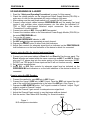
TRUE systems PRECISION 8i 8-CHANNEL PRECISION MICROPHONE PREAMPLIFIER with M/S decoding and Direct Inputs OPERATION MANUAL Version 1.2 SAFETY and OPERATING PRECAUTIONS Important Information: This symbol indicates the presence of dangerous voltage within the product enclosure that presents the risk of electric shock injury. When this symbol appears next to an operation discussed in this manual, only qualified technical personnel should perform that operation. This symbol indicates important operating or maintenance instructions that should be read carefully. Failure to observe these instructions could result in damage to the product or other property. WARNINGS: To reduce the risk of electric shock injury, do not remove the top cover or rear panel. Uninsulated dangerous voltage exists within the product’s enclosure. Refer servicing to qualified personnel. Do not defeat the earth ground connection in the AC power cable. Tips for eliminating ground loops are discussed in the “TROUBLESHOOTING”section of this manual. Do not operate this unit in the presence of rain, liquids or condensing moisture. Liquid entering the product enclosure presents the risk of electric shock injury. Do not touch the AC plug or enclosure with wet hands. Do not defeat intended AC power connection polarization. Do not use a damaged or excessively worn cord to connect this unit to AC power. CAUTIONS: Severe damage may be caused to your unit if the AC voltage setting is not correct for the AC power available in your area. The voltage setting is visible on the AC inlet module on the International Power Supply Module (PSU-P8i). See section on “AC Mains Connection”for instructions on selecting the proper AC voltage setting. If you are unsure about this, contact your dealer or TRUE Systems. Product failure caused by improper voltage setting will not be covered under warranty. Do not operate this unit in the presence of rain, liquids or condensing moisture. Liquid entering the product enclosure is likely to cause performance degradation or failure. Failures due to moisture entering the enclosure will not be covered under warranty. Should liquid spill on the unit, immediately disconnect it from the AC power source and return it to your dealer or TRUE Systems for servicing. This product is designed to operate in an ambient temperature environment not to exceed 50C (122F). Please ensure that this unit is mounted in such a way that vents are not blocked and ambient temperature does not exceed 50C. 2 CERTIFICATIONS Declaration of Conformity – CE Sunrise Engineering and Design Inc. hereby declares the TRUE Systems PRECISION 8i 8-channel microphone preamplifier to be in material conformity with the following directives and related standards: 73/23/EEC – Low Voltage Directive 89/336/EEC – EMC Directive EN60065:1998 EN55103-1: 1997 EN55103-2: 1997 Technical files are maintained at corporate headquarters of Sunrise Engineering and Design Inc., 1634 S. Research Loop, Suite 110, Tucson, Arizona 85710, USA. Owner’s Record We recommend that you record the following information for reference in the event that you need to contact TRUE Systems for technical support or repairs. Please return your completed Warranty Card today. Serial No._____________________ Purchase Date ______________________ Dealer _____________________________________________________________ Address ____________________________________________________________ Phone _______________________ 3 PRECISION 8i OPERATION MANUAL CONTENTS SAFETY and OPERATING PRECAUTIONS 2 CERTIFICATIONS 3 Owner’s Record 3 Table of Contents 4 INTRODUCTION 5 PRODUCT OVERVIEW 5 UP-AND-RUNNING IN A HURRY 6 INSTALLATION 7 7 8 8 Unpacking and Inspection Mounting Ventilation OPERATION Connections AC Mains Connection Output Cable Connection Microphone Cable Connection A Word About Cables Front Panel Controls More About M/S Decoding 8 8 8 10 11 11 12 14 DESIGN APPROACH 16 SPECIFICATIONS 16 TROUBLESHOOTING 17 REGISTRATION and WARRANTY 18 SERVICE and SUPPORT INFORMATION 19 4 PRECISION 8i OPERATION MANUAL INTRODUCTION The PRECISION 8i is designed to provide the detailed, transparent sonic performance necessary for the most critical direct tracking and live sound applications. It includes a unique combination of functions that make it useful as a complete input system for standalone or PC-based recording systems. And, the PRECISION 8i has special features that provide the serious musician or recordist with useful tools to get the best sound more quickly and easily. We appreciate the confidence you have placed in TRUE Systems by purchasing this product. Please feel free to contact us with questions or comments. And, we always appreciate hearing about successful projects you have completed. OVERVIEW In addition to our acclaimed TRUE preamps, PRECISION 8i features two instrument direct inputs (DI’ s) that offer sonic performance previously thought to be available only with dedicated, high-end DI’ s. You’ ll get incredible articulation and control for electric bass, detail and smoothness for stringed instruments and keyboards The 5-segment peak-hold level metering with selectable peak reference allows rapid optimization of program levels between the PRECISION 8i and devices to which it is interfaced. Dual output connections provide easy interconnection as well as the ability to act as a mic splitter. PRECISION 8i is ideal for location recording due to its compact, 1U rack size, 8channel format, useful level metering and easy interconnect. The integral M/S decoder provides creative spatial image control and can be particularly useful in attaining an exciting stereo image with minimum effort and microphone re-positioning. The M-S microphone technique can be employed effectively in a wide variety of circumstances, from classical ensemble, to drum kit overheads, to solo vocal or instrument – whenever accurate capture of the performance and its acoustical space is desired. M-S micing also eliminates the “hole-in-the-middle”effect. In addition to the previously mentioned features, the PRECISION 8i includes: Both 8-channel DB25 and individual TRS output connections - for easy connectivity. Individual Polarity Reverse - to correct polarity inversions caused by mic position or cable wiring variations. Individual Phantom Power (48V) – available on the front panel. 5 PRECISION 8i OPERATION MANUAL UP-AND-RUNNING IN A HURRY 1. Read the “Safety and Operating Precautions”on page 2 of this manual. 2. Check the voltage selector on the International Power Supply Module (PSU-P8i) to make sure it is set for the appropriate AC mains voltage in your area. 3. After making sure the main power switch is off, connect the AC power cord. 4. Connect output signal cables between PRECISION 8i and the analog line level inputs of your recorder, mixer, signal processor, etc. Use either the individual 1/4” TRS or DB25 eight-channel balanced output connectors. See the section “Connections”for wiring details. 5. Connect mic cables to MIC 1 through MIC 8 as needed. 6. Connect the interface cable on the International Power Supply Module (PSU-P8i) to the main PRECISION 8i unit. 7. Turn on the AC power. 8. Set PEAK REFERENCE selector to +26. 9. Set 48V and buttons as appropriate on each channel. 10. Depress the RESET button to clear Peak-Hold indicators. 11. Adjust Gain controls for adequate signal level as indicated on the PRECISION 8i level indicators or on the level indicators of the device to which it is connected. If you’re using the DI’s for electric instrument input: 1. Connect your instrument cables to Direct In 1 and Direct In 2 on the rear panel. The Direct In jacks are located within the same connectors as MIC 7 and MIC 8. Simply plug your 1/4”phone plug into the center portion of the desired connector. NOTE: DO NOT use TRS plugs for these inputs as the DI will not function correctly. 2. Set buttons as appropriate. 3. Adjust DI-1 or DI-2 Gain controls for adequate signal level as indicated on the PRECISION 8i level indicators or on the level indicators of the device to which it is connected. If you’re using the M/S Decoder: 1. Connect the cardioid or omni MID mic to MIC 1 input. 2. Connect the figure 8 SIDE mic to MIC 2 input. Face the SIDE mic toward the right side of the sound field (perpendicular to the axis of the MID mic). See Figure 1. 3. Depress the MID-SIDE ON button. “Left”signal is routed to Channel 1 output. “Right” signal is routed to Channel 2 output. 4. Adjust the Channel 1 gain control for adequate mono signal level. 5. Adjust the Channel 2 gain control to vary the image width as desired. 6. See the section “More About M-S Decoding”for more information. MID Figure 1 M-S microphone orientation SIDE 6 PRECISION 8i OPERATION MANUAL About the Level and Peak-Hold Indicators: 1. SIG indicates that a signal is present on the channel. It illuminates when the signal level exceeds -24dBu. 2. +4 illuminates when the output signal reaches normal operating level of +4 dBu. 3. OL illuminates when the signal level exceeds +26 dBu, which is 5 dB below the overload point for the Precision 8i. 4. The PEAK-HOLD indicators (PK,-3,-6) activate when the output signal level exceeds the level set on the PEAK REFERENCE switch. 5. For example: With PEAK REFERENCE set to +26 the PK indicator illuminates (and stays on) at +26dBu, the -3 indicator illuminates at +23 dBu and the -6 indicator illuminates at +20 dBu. 6. NOTE: Only the OL light indicates impending preamp overload. The red PK light simply indicates that the signal has exceeded the level selected on the PEAK REFERENCE switch. 7. Push the RESET button to reset the PEAK-HOLD indicators for all channels. (It is normal for power-on transients and phantom power transients to activate the PEAKHOLD indicators. Simply depress RESET to clear the indicators.) INSTALLATION Unpacking and Inspection We recommend that you inspect your PRECISION 8i upon unpacking it from the factory shipping carton. In the unlikely event that the unit exhibits any physical damage, DO NOT connect it to the AC mains power, but contact your dealer immediately. In addition to the PRECISION 8i, the shipping carton should also include: An International Power Supply Module (PSU-P8i) An AC power cord A warranty registration card A “Caution”sheet This Operation Manual We recommend that you keep the shipping carton and foam supports in the event that the unit must be shipped at some time in the future. DO NOT package the unit in “packing peanuts”or similar material as it will settle during shipping and damage will likely occur. If original packing materials cannot be located, wrap the unit with a liberal amount of plastic “bubble wrap”material extending at least 2”beyond the extremities of the PRECISION 8i enclosure. 7 PRECISION 8i OPERATION MANUAL Mounting The PRECISION 8i is designed for conventional rack mounting, or stand-alone mounting by use of the adhesive rubber feet supplied. Avoid locating the unit next to equipment that emits strong electromagnetic fields. If the unit is to be permanently mounted in a high-vibration environment, you may wish to provide additional side or rear support to prevent possible distortion of the mounting ears. Do not locate the unit where it is exposed to rain, moisture, or liquid spills. Do not locate the unit where it is exposed to temperature extremes. Do not mount the Power Supply Unit closer than one rack space from the preamp unit. This avoids coupling unwanted magnetic interference into the preamp unit. Ventilation We recommend that you provide adequate ventilation so that the air temperature surrounding the unit does not exceed 55C (122F). If multiple units are to be mounted in a poorly ventilated rack or travel case, a 1 3/4”blank space should be located after every two units (two units mounted together, blank space, two more units, etc.). OPERATION Connections PSU-P8i 1 240 AC Mains Connection: Prior to connecting the AC mains power cord to the Power Supply Unit, verify that the Voltage Selector is set for the AC mains voltage in your area. The currently selected voltage appears in the window on the Fuse Drawer 1 . It is important that the voltage is set correctly for both safety reasons and to insure that the PRECISION 8i will operate according to specifications. Note also that the correct fuse type must be used. See Table below. Product damage caused by incorrect voltage settings or fuse selections cannot be covered under warranty. 8 PRECISION 8i OPERATION MANUAL To change the AC operating voltage selection: This procedure should be performed only by qualified technical personnel. If you are not qualified, please consult TRUE Systems or your dealer for assistance. 240 2 1 1) Using an appropriate AC voltmeter, measure the AC line voltage at the installation site. 2) Make sure the AC power cord is disconnected from the PSU-P8i Power Supply Unit. 3) Using a small screwdriver or similar tool, release the latch on the Fuse Drawer 1 and pull it (and the fuses) out of the AC inlet module. 4) Using a small screwdriver or similar tool, remove the Voltage Selector 2 . 5) Rotate the Voltage Selector to the appropriate position for the AC voltage measured in Step 1) above. See Table below for proper Voltage Selector setting. Select the setting that places your measured voltage nearest the middle of the Operating Voltage Range. Voltage Selector 100V 120V 220V 240V Operating Voltage Range 90-110VAC 50/60Hz 110-132VAC 50/60Hz 201-240VAC 50/60Hz 220-264VAC 50/60Hz Fuses (2)____ T 500mA L, 250V T 500mA L, 250V T 315mA L, 250V T 315mA L, 250V For other operating voltage options, consult TRUE Systems. CAUTION: To provide continued protection against fire, replacement fuses should be only of the types listed above. Note that two (2) fuses are necessary and that both fuses 9 PRECISION 8i OPERATION MANUAL must be of the same type. AC mains power cord must be removed to gain access to Fuse Drawer 1 for fuse replacement. 3 4 TRUE Systems - Precision 8i Sunrise Engineering and Design Inc. Tucson, Arizona USA LINK CONNECT ONLY PSU-P8i 7 5 3 1 8 6 4 2 DO NOT DISCONNECT WITH AC POWER ON S/N 1-8 (4-40) BALANCED OUT Signal Ground Connection: LINK 3 connects signal ground to earth ground. Signal ground is isolated from earth ground if the LINK jumper is removed. This jumper will normally be installed. See “Troubleshooting”section for usage tips. Output Cable Connection: For ease of connection, we’ ve provided two styles of balanced output connector: 8-channel DB25 and individual TRS 4 . Both output types are electrically equivalent and may be used simultaneously to connect to Line Inputs on mixing consoles, recorders, etc. If both pairs of outputs are used, care should be taken to avoid system ground loops. See “Troubleshooting”section for tips on avoiding hum caused by grounding problems. The DB25 and TRS output connectors are not electronically isolated. Therefore, if you chose to connect either one of the output connectors to an unbalanced input, the other connector will automatically be unbalanced. When connecting an output of the PRECISION 8i to an unbalanced input, you must connect the negative signal pin (pin 3 of the XLR or “ring”of the TRS) to the shield. Failure to do this will result in audible distortion. The wiring configuration used for the output connectors on the PRECISION 8i is: For TRS: Tip is positive (+) Ring is negative (-) Sleeve is shield For DB25: This output connector is wired according to the Tascam 8-channel analog wiring configuration. DO NOT USE TDIF CABLES. 1 2 3 4 5 6 7 8 S - +S - +S - +S - +S - +S - +S - +S - + 13 25 10 1 14 PRECISION 8i OPERATION MANUAL 5 6 MIC 8 MIC 7 Direct In 2 Direct In 1 MIC 6 MIC 5 MIC 4 MIC 3 MIC 2 MIC 1 PIN 2 + PIN 3 - MS Microphone Connection: Microphone connection is made to standard XLR receptacles on the rear panel. The wiring configuration used for the microphone connectors on the PRECISION 8i is: Pin 2 is positive (+) Pin 3 is negative (-) Pin 1 is shield Do not attempt to connect unbalanced microphones (with single-pin connectors) to the PRECISION 8i. It is not intended to operate with this type of microphone. CAUTION: We recommend that you avoid “hot-patching”microphone inputs when using a patch bay at the microphone inputs of the PRECISION 8i. Please TURN OFF phantom power and turn down the gain prior to connecting or re-patching microphone inputs routed through a patch bay. Failure to do so may result in transients that can damage the PRECISION 8i or equipment that is connected to its outputs-not to mention your ears! Electric Instrument Connection: Dual-purpose input connectors 5 are available on channels 7 and 8. Insert XLR microphone connector for normal MIC 7 and MIC 8 operation. Insert 1/4" phone plug for use as Direct Input for instruments DI-1 and DI-2. DI-1 and DI-2 are controlled by Gain and (phase) controls for channels 7 and 8, respectively. The gain range for the direct inputs is from -4 dB to +44 dB. NOTE: DO NOT use TRS plugs for these inputs as the DI will not function correctly. M-S (mid-side) Microphone Connection: You may note the M-S (mid-side) connection symbol below the MIC 1 and MIC 2 connectors 6 . This is simply a visual reminder, when using an M-S mic setup, to connect the MID mic to channel 1 and the SIDE mic to channel 2. See the section “More About M-S Decoding”for more information. A Word About Cables..... Most users of the PRECISION 8i have invested much time and money in their selection of microphones and preamplifiers. We recommend that you give some consideration to the microphone, instrument and output cables you select, as well. 11 PRECISION 8i OPERATION MANUAL Use high-quality, low capacitance cable. Braided shielding and “star quad” type mic cables will perform better in electrically noisy environments. Manufacturers such as Canare, Mogami (and others) make high performance cable of this type. Some “house brand”cables are made by quality manufacturers, but others can be inferior. Be careful. Use cables with high-quality connectors (Neutrik, Switchcraft, etc.). Our studio testing has shown that some of the more esoteric guitar/instrument “super-cables”do, indeed, sound better. Noticeable improvement, but at a stiff price. Try before you buy! Avoid excessive cable length. Replace damaged connectors. Front Panel Controls 4 3 OL PK 30 35 8 OL 40 -3 TRUE systems -6 Ø 50 55 SIG 35 30 OL 40 -3 45 48V +4 PK 16 -6 1 50 +4 ON MID Ø SIG 30 35 -3 45 48V 64 PK 55 64 16 SIDE -6 48V 2 +4 Ø SIG 16 3 2 6 1 7 5 1 Phase reverse selector. Output signal polarity is reversed when the button is depressed. 2 Phantom power selector. Phantom power (+48V) is activated when the 48V button is depressed. Avoid selecting phantom power if you are using a ribbon microphone. While not required, it is advisable to de-select 48V when using a dynamic microphone or a DI input. 3 Overload warning indicator. OL illuminates (and holds) at +26 dBu which is 5 dB below actual overload. Depress RESET 10 to clear OL. 4 Peak-Hold indicators. These are provided to help optimize level setting when the PRECISION 8i is remotely located from the device to which it is connected. The PK indicator activates (and holds) at the level selected on the PEAK REFERENCE selector 9 . The -3 indicator activates at peak level minus 3 dB. The -6 indicator 12 PRECISION 8i OPERATION MANUAL activates at peak level minus 6 dB. Generally, the PEAK REFERENCE selector is set for the maximum level you want to present to your mixing console, recorder, etc. Depress RESET 10 to clear PK. NOTE: Only the OL light indicates impending preamp overload. The red PK light simply indicates that the signal has exceeded the level selected on the PEAK REFERENCE switch. Note that the overload level of the PRECISION 8i is +31dBu at the output. This level exceeds the input capability of some devices (check manufacturer’ s specifications). In other words, it may be possible to cause overload distortion in the connected device even though the PRECISION 8i level indicator does not show a red light. We can provide accessory Output Attenuators in applications where this is necessary. Please consult the factory for assistance. 5 Signal Present indicator. The SIG indicator activates at approximately -24 dBu. 6 Operating level indicator. The +4 indicator activates when the output level reaches +4 dBu normal operating level. When the PEAK REFERENCE selector 9 is set to the -10 dBV position, the operating level indicator activates at -10 dBV output level. 7 Mid-Side mode selector. When the ON button is depressed, Channel 1 output becomes “Left”and Channel 2 output becomes “Right”. The Channel 1 gain control adjusts the mono signal level applied to both the Left and Right outputs. The Channel 2 gain control adjusts the stereo image width. 8 Gain control. This control adjusts the preamp gain over the range of 16 dB to 64 dB. 12 OL 40 PK 35 30 OL 40 -3 45 50 45 50 48V 55 +4 Ø SIG 35 30 40 -3 -6 64 PK +4 64 7 Ø DI 1 50 48V 55 16 45 -6 SIG 55 16 8 P R E C IS IO N 8 +20 64 DI 2 +24 +26 +22 +18 RESET -10 dBV PEAK REFERENCE 9 11 10 13 PRECISION 8i OPERATION MANUAL 9 PEAK REFERENCE selector. This sets the level at which the Peak-Hold indicators 4 activate. It also changes the operating level indication 6 to -10 dBV operation when the -10 dBV position is selected. 10 Peak-Hold reset. RESET clears the peak-hold indicators on all channels. NOTE: It is normal for the Peak-Hold indicators to activate when phantom power is applied, when AC power is applied, or when a new setting is made on the PEAK REFERENCE selector - simply depress RESET to clear the indicators. 11 Direct inputs DI-1 and DI-2 are controlled by gain controls for channels 7 and 8, respectively. The gain range for the direct inputs is from -4 dB to +44 dB. 12 AC power indicator. The green power LED indicates that the unit is on. More About M-S Decoding: M-S (Mid-Side) decoding is a particularly creative feature of the PRECISION 8i. While the M-S microphone technique has been around for many years, the opportunity to use it is frequently limited by the need for specialty microphones and/or decoders. What is M-S? It is a stereo microphone placement technique that uses a center, forward-facing omni or cardioid mic (Mid) and a side-facing figure 8 mic (Side). The signals from these two mics are passed through matrix circuitry that combines them in particular phase and level relationships to produce a stereo L and R output. MID SIDE What good is M-S versus the typical XY microphone placement? Originally, M-S was used because it provided a stereo signal with good mono compatibility. While this is not very interesting for contemporary stereo CD’ s, it is still valuable for broadcast and film sound production. But there is another significant benefit: varying the gain of the Side mic in relation to the Mid mic causes a variation in the stereo image - from none, to extreme separation. It is not necessary to change the angle or position of the microphones in order to change the stereo image. This feature can really speed up the time-consuming process of finding a “sweet spot”that provides both good tonal quality and good imaging. What are the best applications for M-S? M-S does an excellent job of capturing the natural sonic perspective of acoustical ensembles. Orchestral and choral recording: use an M-S pair for the central array 14 PRECISION 8i OPERATION MANUAL Drum kits: use an M-S pair for drum overhead micing. Vocal and instrumental ensembles: use M-S to give realistic perspective to backup vocals or instrumental groups. Individual instruments or vocals: try M-S on acoustic guitar and in situations where you wish to capture room ambience. Broadcast/film sound: use M-S to capture audience noise or background ambience. M-S can also be used in TV and film work to match the sonic image width to the visual image width. Optional Level Indicator Modes The Peak-Hold level indicators can operate in two modes. As supplied, only the OL and PK indicators will hold (after they are activated) until RESET is depressed. An optional mode is available which causes the -3 and -6 indicators to also hold until RESET is depressed. This mode can be helpful in live sound and recording applications where the PRECISION 8i is remotely located from the device(s) to which it is connected. Jumpers inside the unit select this optional mode. If you wish to configure the unit for this mode, proceed as follows: WARNING - ELECTRIC SHOCK HAZARD. Dangerous voltage exists inside the enclosure of this product. This operation should only be performed by qualified personnel. NEVER open the product enclosure while the AC power cord is attached. Disconnect AC power cord. Remove the twelve screws securing the top cover to the enclosure. Remove the cover. Locate the eight upright printed circuit boards along the front panel. Select level indicator mode by setting jumpers (J2) as shown below. J2 J2 Normal Mode (OL, PK remain on) Optional Mode (OL, PK, -3, -6 remain on) Replace cover and secure with twelve screws. Make sure no tools, loose hardware, debris, etc. remain in the unit prior to attaching the cover. 15 PRECISION 8i OPERATION MANUAL DESIGN APPROACH PRECISION 8i features a high-voltage composite architecture with discrete devices plus integrated circuits. The totally balanced, dual servo, dc-coupled design provides exceptional transient response, headroom, imaging and noise performance. Critical devices have been selected on the basis of extensive listening tests as well as engineering tests. Military grade, hand-matched components are utilized in critical circuit areas. These design features result in the transparent, detailed sound quality for which TRUE preamps have become known. SPECIFICATIONS Gain, preamp: DI: 15.5 to 64dB –4 to 44dB Frequency Response: (gain=40dB) 1.5 Hz to 500kHz (-3dB) Maximum Output Level: +31 dBu Maximum Input Level: +15 dBu Noise (Rs=0 Ohms): -132 dB e.i.n. Slew Rate: >40 V/uS CMRR (CMV= +10 dBu): 85 dB THD (preamp) (+26dBu, 100kOhm): .0008% Input Impedance, preamp: DI: 5.5 kOhm 2.5 Mohm Power Consumption: 44W Preamp Enclosure Dimensions: 17.5 in. (44.5 cm) W, 13.75 in. (35 cm) D, 1.75 in. (4.5cm) H 1 in. (2.5cm) 6.63 in. (16.8 cm) W, 6.4 in. (16.3 cm) D, 1.75 in. (4.5cm) H 3 in. (7.6 cm) 10.2 lbs. (4.6 Kg) 5.0 lbs. (2.3Kg) Preamp Front Panel Extension: Power Supply Unit Dimensions: Power Supply Unit Height: Power Supply Unit Rear Extension: Preamp Weight: Power Supply Unit Weight: Typical performance. Specifications subject to change without notice. 16 PRECISION 8i OPERATION MANUAL TROUBLESHOOTING T Solution Symptom No signal output. Main power switch Check AC power source and cord. is on, but no LED’ s are illuminated. Check fuses (pull fuse drawer next to power cord inlet) No signal output. Main power switch Check status of phantom power. is on and green power LED is Check continuity of mic and illuminated. instrument cables. Check continuity of output cables. electric Output signal is distorted. Outputs Make sure gain is adjusted so that the OL are connected for balanced indicator does not activate during the audio operation. program. Make sure the high output capability of this unit is not overloading the device or monitoring system to which it is connected. Set PEAK REFERENCE selector to match capability of device or monitoring system, then adjust gain according to indications on the Peak-Hold LEDs. Check continuity of output cable. Make sure outputs are not connected to a load impedance of less than 600 ohms. Output signal is distorted. Outputs Make sure the minus (-) output signal pins are are connected for unbalanced connected to the shield and not left operation. unconnected. See “Output Cable Connection” section. Check troubleshooting tips for balanced operation (above). Hum can be heard in the audio Disconnect grounding LINK. program. Check continuity of output cables (particularly shields). Disconnect shields on one end of output cables. Connect grounding LINK. If both outputs (TRS, DB25) are in use, try disconnecting shields on DB25 only, or TRS only. 17 PRECISION 8i OPERATION MANUAL Channel 1 signal can be heard in Check status of M-S selector. It should be Channel 2 output - and vice versa. “out”for individual channel mode and “in”for Mid-Side mode. Channel 2 seems to have no output Check status of M-S selector. It should be when used with Channel 1 as a “out”for individual channel mode and “in”for stereo pair Mid-Side mode. Make sure the selectors for both Channels 1 and 2 are “out”. In M-S mode the stereo channels Make sure the front of the bi-directional “Side” are reversed (Channel 1 is Right mic is aimed 90 degrees to the right of the and Channel 2 is Left) axis of the “Mid”mic. In M-S mode the stereo channel Make sure the selectors for both Channels 1 phasing is incorrect and 2 are in the same position. Electric instrument connected to a Check continuity of electric instrument cables. Direct Input does not produce a Check the batteries or AC power source of signal or signal is distorted. any “foot pedal”effects processors connected to the Direct Input. Make sure that the instrument cables have standard tip-sleeve 1/4” phone plugs. - DO NOT use TRS plugs. Radio Frequency Interference can Make sure that mic cables are of good quality be heard in the audio program and that the shield is properly connected. (swishing sound or audio from a Avoid excessive length. radio transmitter). Make sure that earth ground connection is maintained via the AC power cord - DO NOT use an isolator. Make sure the unit is located away from known sources of radio frequency energy. . REGISTRATION and WARRANTY Don’ t forget to register your PRECISION 8i by filling out the enclosed Registration Card and returning it to us. This allows TRUE Systems to contact you regarding any updates, upgrades or applications information that may become available. SUNRISE ENGINEERING and DESIGN INC. (“SUNRISE”) warrants the TRUE systems PRECISION 8i to be free from defects in material and manufacture, when properly installed and used according to instructions in the Operation Manual, for a period of one year from the date of sale to the original purchaser. Units returned for warranty repair to SUNRISE or an authorized TRUE Systems repair facility will be 18 PRECISION 8i OPERATION MANUAL repaired or replaced at the manufacturer’ s option, free of charge. Supplementary shipping charges will apply to units returned to addresses outside the continental USA. All units returned to SUNRISE or authorized TRUE systems repair facility must be prepaid, insured and properly packaged. Purchaser must obtain a Return Authorization (RA) number from SUNRISE prior to returning a product. SUNRISE may require proof of the purchase date in the form of a copy of a dated original retail invoice. This warranty is void if, in the sole judgment of SUNRISE, the product has been abused, neglected, misapplied, or has been damaged by an accident, modification, or attempted repair by unauthorized personnel. This warranty will not apply to cosmetic damage incurred due to normal handling and use. SUNRISE reserves the right to change or improve the product design at any time without prior notice. Incorporation of design changes in future versions of the product does not imply the availability of upgrades for existing units. This warranty is in lieu of all other warranties, expressed or implied, and SUNRISE specifically disclaims all implied warranties, including, but not limited to, warranties of merchantability and fitness for a particular purpose. The purchaser acknowledges and agrees that in no event shall SUNRISE be held liable for any special, indirect, incidental or consequential damage, or for injury, loss or damage sustained by any person or property, that may result from the use of, or failure of this product to operate correctly at any time. In the USA, some states do not allow the exclusion or limitation of implied warranties or liability for incidental or consequential damage, so the previous exclusion may not apply to you. This warranty gives you specific legal rights, and you may have other rights which vary from state to state. SERVICE INFORMATION Other than cleaning the exterior surfaces of your PRECISION 8i and occasional inspection of the AC power cord and audio cables for damage, no maintenance procedures should be attempted by the user. Cleaning can be performed using a lintfree cloth dampened with Windex. There are no user-serviceable components inside the product enclosure. Many of the electronic components are selected and matched at the factory. For this reason, as well as personal safety considerations, we recommend that you refer service requirements to TRUE Systems or authorized repair facilities. All units returned to TRUE systems or authorized TRUE systems repair facility must be prepaid, insured and properly packaged. Purchaser must obtain a Return Authorization (RA) number from SUNRISE prior to returning a product. Sunrise Engineering and Design Inc. 1634 S. Research Loop, Suite 110 Tucson, Arizona 85710 USA Tel: +1 520-721-2735 Fax: +1 520-722-4057 Email: [email protected] 19