1
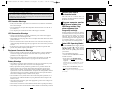
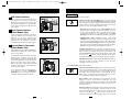
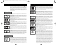
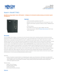
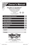
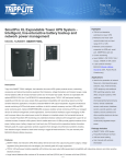
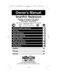
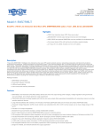
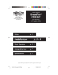
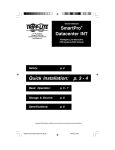
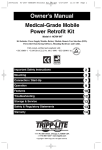
200310044 SmartPro XL Owner’s Manual 93-2078.qxd
10/9/2003
4:20 PM
Page 1
Owner’s Manual
SmartPro®
120V Input/Output, Line-Interactive UPS Systems
UL 1778
Important Safety Instructions
2
Quick Installation
3
Basic Operation
5
Storage & Service
8
Specifications
8
Español
9
Français
19
1111 W. 35th Street Chicago, IL 60609 USA
Customer Support: (773) 869-1234 • www.tripplite.com
Copyright © 2003 Tripp Lite. All rights reserved. SmartPro® is a registered trademark of Tripp Lite.
1
200310044 SmartPro XL Owner’s Manual 93-2078.qxd
10/9/2003
4:20 PM
Page 2
Important Safety Instructions
SAVE THESE INSTRUCTIONS
Quick Installation
1
This manual contains instructions and warnings that should be followed during the
installation, operation and storage of all Tripp Lite UPS Systems. Failure to heed these
warnings will void your warranty.
UPS Location Warnings
Connect your UPS to
an electrical outlet.
Your UPS will run a self-test after it is
plugged in. See Basic Operation to understand
the results of its self-test.
2
• Install your UPS indoors, away from excess moisture or heat, conductive contaminants,
dust or direct sunlight.
• For best performance, keep the indoor temperature between between 32º F and 104º F
(0º C and 40º C).
• Leave adequate space around all sides of the UPS for proper ventilation.
Plug your computer, monitor
and external modem into
UPS/Surge outlets. Plug
other equipment into
Surge-only outlet(s).
1
EXTERNAL
BATTERY
NORM
SEE MANUAL FOR
PROPER CONNECTION
Separate UPS/Surge and Surge-only outlet(s)
are identified on the back of your UPS. Your
UPS is designed to support only computer
equipment. You will overload your UPS if
you connect high power draw equipment such
as household appliances, laser printers or
surge suppressors to its UPS/Surge outlets.
UPS Connection Warnings
• Connect your UPS directly to a properly grounded AC power outlet. Do not plug the
UPS into itself; this will damage the UPS.
• Do not modify the UPS's plug, and do not use an adapter that would eliminate the UPS’s
ground connection.
• Do not use extension cords to connect the UPS to an AC outlet. Your warranty will be
voided if anything other than Tripp Lite surge suppressors are used to connect your UPS to
an outlet.
• If the UPS receives power from a motor-powered AC generator, the generator must
provide clean, filtered, computer-grade output.
Equipment Connection Warnings
• Do not use Tripp Lite UPS Systems for life support appliances in which a malfunction
or failure of a Tripp Lite UPS System could cause failure or significantly alter the
performance of a life-support device.
• Do not connect surge suppressors or extension cords to the output of your UPS. This
might damage the UPS and will void the surge suppressor and UPS warranties.
Battery Warnings
• Your UPS does not require routine maintenance. Do not open your UPS for any reason
except battery replacement. There are no user-serviceable parts inside.
• Battery replacement must be performed by qualified service personnel. Because the
batteries present a risk of electrical shock and burn from high short-circuit current,
observe proper precautions. Unplug and turn off the UPS before performing battery
replacement. Use tools with insulated handles, and replace the existing batteries with the
same number and type of new batteries (Sealed Lead-Acid). Do not open the batteries.
Do not short or bridge the battery terminals with any object.
3
Select UPS Operating Mode.*
Press the ON/OFF button to toggle your UPS
between the UPS (“ ” LED lit) and the
CHARGE ONLY (“
” LED flashing)
modes. Choose the operating mode based on
your location:
USA, Canada & Western Europe:
• Leave the UPS in the UPS mode at all times.
All Other Countries:
• Put the UPS in the CHARGE ONLY
mode when you are not using connected
equipment.
(WARNING! When set to “CHARGE ONLY,” the UPS
will not provide battery backup during a blackout or
brownout)
• Put the UPS in the UPS mode when you
are using connected equipment.
*See Basic Operation section for a complete explanation
of each mode.
• The UPS batteries are recyclable. Refer to local codes for disposal requirements, or in
the USA only call 1-800-SAV-LEAD for recycling information. Do not dispose of the
batteries in a fire.
• Only connect Tripp Lite battery packs of the appropriate type and correct voltage to the
external battery connector.
• Do not connect or disconnect external batteries while the UPS is operating from battery.
• Do not attempt to connect external batteries to models without an external battery connector.
2
2
3
3
DELAY
200310044 SmartPro XL Owner’s Manual 93-2078.qxd
Quick Installation
10/9/2003
4:20 PM
Page 4
Basic Operation
optional
These connections are optional. Your UPS will function properly without these connections.
1
USB Communications
Use the ON/OFF button to do three things:
EXTERNAL
BATTERY
Use any USB cable to connect the USB port of
your computer to the USB port of your UPS.
Download the PowerAlert UPS monitoring software program appropriate for your operating
system from www.tripplite.com and install it on
your computer.
2
Serial Communications
(Select Models Only)
NORM
DELAY
SEE MANUAL FOR
PROPER CONNECTION
Switch your UPS’s Operating Mode: While your UPS is plugged
into a live AC outlet, press the ON/OFF button and hold it until you
hear a beep (about 2 seconds) to toggle between the following operating
modes. Choose your UPS’s operating mode based on the regional
guidelines in Step 3 of the Quick Installation section.
• UPS Mode: ENABLES battery backup. UPS Conditions: The UPS
charges its battery and supplies power at its receptacles when it is
receiving utility line power. If utility power fails, the UPS provides
power from its batteries. The “ ” indicator light is lit. Setting
Advantages: Provides battery backup during blackouts or brownouts.
1
Use the serial cable provided with your UPS to
connect the DB9 port of your computer to the
DB9 port of your UPS. Download the
PowerAlert UPS monitoring software program
appropriate for your operating system from
www.tripplite.com and install it on your computer.
3
Buttons
• CHARGE ONLY Mode: DISABLES battery backup. UPS
Conditions: The UPS charges its battery and supplies power at its
receptacles when it is receiving utility line power. The “ ” indicator
light is flashing. Setting Advantages: Continues to charge the battery
when power is present while turning OFF the inverter to prevent battery
depletion during power outages when equipment is not in use.
EXTERNAL
BATTERY
NORM
DELAY
SEE MANUAL FOR
PROPER CONNECTION
External Battery Connection
(Select Models Only)
External batteries are only needed to extend runtime.
Adding external batteries will increase recharge
time as well as runtime.
2
The illustration shows the location of your UPS’s
External Battery Connector, where you will
insert the battery pack cable. Complete installation
and mounting instructions for your battery pack
appear in the battery pack’s owner’s manual.
Make sure that cables are fully inserted into their
connectors. Small sparks may result during battery
connection; this is normal.
If you connect more than one external battery,
set the Charge Level switch to EXTERNAL
BATTERY. Your UPS’s charger will increase
its output to handle the additional batteries.
Cold-Start Your UPS: You may “cold start” your UPS and use it as a
stand-alone power source when utility power is not present, providing
that the UPS battery is charged. To “cold start” your UPS, press and
hold the ON/OFF button until you hear a beep (about 2 seconds), then
release it. The “ ” indicator light will illuminate and AC power
inverted from stored battery power will be provided at its receptacles.
EXTERNAL
BATTERY
NORM
SEE MANUAL FOR
PROPER CONNECTION
DELAY
Shut Down Your UPS: Press and hold the ON/OFF button when AC
line power is absent (i.e. during a blackout, or when the UPS is
unplugged) to deactivate your UPS.
Use the MUTE/TEST button to do two things:
3
Silence the UPS On-Battery Alarm: Press and hold this button to
silence the UPS On-Battery alarm, a series of short beeps followed by
a brief pause that is activated when the UPS is providing AC power
from battery. Note: When the battery is nearly depleted, the Low
Battery alarm—a continuous beep that cannot be silenced—will alert
you to immediately shut down connected equipment.
Run a Self-Test: Your UPS performs a self-test whenever it is first
plugged in. To have it run a self-test at another time, leave your
connected equipment on. With your UPS plugged in and in the UPS
mode, press and hold this button until you hear a beep (about 2 seconds) then release it.
Results of a Self-Test: All the LEDs will be lit and the UPS will emit
several short beeps as it momentarily switches to battery to test its
charge and load capacity. The test will last at most 10 seconds. If the
inverter is overloaded, the “ ” LED will stay lit and the UPS will
continue to beep after the test; if this happens, remove some of the load
4
5
200310044 SmartPro XL Owner’s Manual 93-2078.qxd
Basic Operation
10/9/2003
4:20 PM
Page 6
Basic Operation
continued
USB Port: The USB port connects your UPS to any USB workstation
or server. Using this port, your UPS can communicate line-fail and
low-battery status to your computer. Use with Tripp Lite software and
any USB cable to automatically save open files and shut down equipment
during a blackout. See PowerAlert manual.
and run the self-test again. If the batteries seem weak, the “ ” LED
will stay lit and the UPS will continue to beep after the test; if this
happens, let UPS charge its batteries for 12 hours and repeat the test. If
the condition persists, contact Tripp Lite for service. CAUTION: Do
not unplug your UPS to test its batteries. This will remove safe
electrical grounding and may introduce a damaging surge into your
network connections.
DB9 Port (Select Models Only): The DB9 port connects your UPS
to any workstation or server. Use with Tripp Lite’s PowerAlert UPS
monitoring software and a DB9 cable to enable your computer to
automatically save open files and shut down equipment during a
blackout. The UPS can also report power availability and UPS status,
and select UPS models have other capabilities. See PowerAlert manual.
Indicator Lights
All Indicator Light descriptions apply when the UPS is plugged into an AC outlet and turned on.
LINE POWER: This green light will turn ON whenever your UPS is
receiving normal AC line power. It will flash while the UPS is in
CHARGE ONLY mode to indicate that the UPS will not provide battery
backup during a blackout or brownout.
Battery Replacement Door: Under normal conditions, the original
battery in your UPS will last several years. Battery replacement
should be performed only by qualified service personnel. Refer to
“Battery Warnings” in the Safety section on page 2.
BATTERY POWER: This light indicates battery charge level:
Green means the batteries are fully charged or nearly so, yellow
means the batteries are partially charged, and red means the batteries
are nearly depleted.
External Battery Connector (Select Models Only): Use to connect
battery pack(s) for additional runtime. Refer to Specifications and/or
the label next to the connector to determine the appropriate variety of
battery pack to use. Refer to the battery pack instruction manual for
complete installation information and important safety warnings.
VOLTAGE REGULATION: This light will turn ON when your
UPS is automatically correcting high or low utility line voltage. The
UPS will also click gently when this automatic voltage regulation is
operating. These are both normal functions of your UPS, and no
action is required on your part.
Input Breaker: Prevents high input current from damaging the UPS or the
attached load. If this breaker trips, make sure your UPS is connected
to nominal 120V AC power before resetting the circuit breaker by
pushing the breaker switch in to reset.
BATTERY CHARGE: This red light will turn ON continuously
after the UPS runs a self-test to indicate that the UPS’s battery is weakly
charged. If it remains lit after you have allowed the UPS to charge for
twelve hours and have run a second self-test, contact Tripp Lite for
service.
OVERLOAD: This light shows how heavy is the load on the UPS’s
inverter. Green indicates a light load, yellow indicates a medium load,
and red indicates a heavy load (above 85% of the UPS’s output capacity).
If this light is flashing, the UPS is overloaded and will not be able to
provide power to connected equipment during a power outage.
Unplug equipment from the UPS until this LED stops flashing.
Other UPS Features
AC Receptacles: These output receptacles provide your connected
equipment with AC line power during normal operation and battery
power during power outages. The UPS protects equipment connected to these receptacles against damaging surges and line noise. If you
have a USB or DB9 connection to your UPS, you can remotely
reboot connected equipment by turning its receptacles OFF and ON
using Tripp Lite software. Select models have a receptacle that may
be remotely switched ON and OFF without interrupting power to
6
continued
Charge Level Switch: This switch should be set to the left unless
you have connected multiple external batteries, in which case you
may set it to EXTERNAL BATTERY, increasing your charger’s output
so the additional batteries recharge faster.
NORM
DELAY
Power Sensitivity Adjustment: This dial is normally set fully counterclockwise, which enables the UPS to protect against waveform
distortions in its AC input. When such distortion occurs, the UPS will
normally switch to providing PWM sine wave power from its battery
reserves for as long as the distortion is present. In areas with poor utility
power or where the UPS’s input power comes from a backup generator,
chronic waveform distortion could cause the UPS to switch to battery too
frequently, draining its battery reserves. You may be able to reduce how often
your UPS switches to battery due to waveform distortion by experimenting
with different settings for this dial. As the dial is turned clockwise,
the UPS becomes more tolerant of variations in its input power’s AC
waveform. NOTE: The further the dial is adjusted clockwise, the
greater the degree of waveform distortion the UPS will allow to pass to
connected equipment. When experimenting with different settings for
this dial, operate connected equipment in a safe test mode so that the
effect on the equipment of any waveform distortions in the UPS’s
output can be evaluated without disrupting critical operations.
7
200310044 SmartPro XL Owner’s Manual 93-2078.qxd
10/9/2003
4:20 PM
Page 8
Storage & Service
Manual de operación
Storage
All connected equipment should be turned off, then disconnected from the UPS to avoid battery
drain. Unplug your UPS from its AC receptacle, then press and hold its ON/OFF button to deactivate
it. Your UPS is now ready for storage. If you plan on storing your UPS for an extended period
of time, fully recharge the UPS batteries once every three months by plugging the UPS into
a live AC outlet and letting the UPS charge for 4 to 6 hours. If you leave your UPS batteries
discharged for an extended period of time, they will suffer a permanent loss of capacity.
SmartPro® XL
Sistemas UPS de 120V de entrada/salida, interactivos,
con tiempo de respaldo extendido
Service
If returning your UPS for service, contact your local Tripp Lite dealer or distributor. They will
refer you to a service center. Please carefully pack the UPS using the ORIGINAL PACKING
MATERIAL that came with the unit. Enclose a letter describing the symptoms of the problem.
If the UPS is within the warranty period, enclose a copy of your sales receipt.
Specifications
Tripp Lite has a policy of continuous improvement. Specifications are subject to change without notice.
Model:
Series:
Input Voltage/Frequency:
Output Capacity (VA/Watts):
Battery Runtime
(Half Load/Full Load) Minutes:
Battery Recharge Time:
Approvals:
Model:
Series:
Input Voltage/Frequency:
Output Capacity (VA/Watts):
Battery Runtime
(Half Load/Full Load) Minutes:
Battery Recharge Time:
Approvals:
SMART700
AGSM1050PJR3
SMART750XL
AGSM1500XPSR3
SMART1050
AGSM1050PJR3
120V/60 Hz
700/600
120V/60 Hz
750/600
120V/60 Hz
1050/800
20/6
2-4 hrs.
UL, cUL, NOM, FCC B
42/18*
2-4 hrs.*
UL, cUL, NOM, FCC A
23/8
2-4 hrs.
UL, cUL, NOM, FCC B
SMART1050XL
AGSM1500XPSR3
SMART1500
AGSM1500XPSR3
SMART1500XL
AGSM1500XPSR3
120V/60 Hz
1050/800
120V/60 Hz
1500/980
120V/60 Hz
1500/980
26/6*
2-4 hrs.*
UL, cUL, NOM, FCC A
20/7
2-4 hrs.
UL, cUL, NOM, FCC A
20/7*
2-4 hrs.*
UL, cUL, NOM, FCC A
UL 1778
Importantes instrucciones de seguridad
10
Instalación rápida
11
Operación básica
13
Almacenamiento y servicio
17
Ficha técnica
17
English
1
Français
19
*External battery packs can be connected to these models. External battery packs will increase both the battery runtime and
the battery recharge time.
ALL UNITS:
Output Waveform Line Mode (filtered sinewave); Output Waveform Battery Mode (PWM sine wave); AC Surge Suppression (exceeds
IEEE 587 Cat. A & B standards); AC Noise Attenuation (>40 dB at 1MHz); AC Protection Modes (H to N, H to G, N to G); Tripp Lite
External Battery Model (BP36V27).
FCC CLASS A RADIO/TV INTERFERENCE NOTICE:
Note: This equipment has been tested and found to comply with the limits for a Class A digital device, pursuant to Part 15 of the
FCC Rules. These limits are designed to provide reasonable protection against harmful interference when operated in a commercial environment. This equipment generates, uses and can radiate radio frequency energy, and if not installed and used in
accordance with the instruction manual, may cause interference to radio communications. Operation of this equipment is likely to
cause harmful interference in which case the user will be required to correct the interference at his own expense. The user must
use shielded cables and connectors with this product. Any changes or modifications to this product not expressly approved by the
party responsible for compliance could void the user's authority to operate the equipment.
FCC CLASS B RADIO/TV INTERFERENCE NOTICE:
Note: This equipment has been tested and found to comply with the limits for a Class B digital device, pursuant to Part 15 of the
FCC Rules. These limits are designed to provide reasonable protection against harmful interference in a residential installation.
This equipment generates, uses and can radiate radio frequency energy, and if not installed and used in accordance with the
instruction manual, may cause interference to radio communications. However, there is no guarantee that interference will not
occur in a particular installation. If this equipment does cause harmful interference to radio or television reception, which can be
determined by turning the equipment off and on, the user is encouraged to try to correct the interference using one or more of the
following measures: reorient or relocate the receiving antenna; increase the separation between the equipment and the receiver;
connect the equipment into an outlet on a circuit different from that which the receiver is connected; consult the dealer or an experienced radio/television technician for help. The user must use shielded cables and connectors with this product. Any changes or
modifications to this product not expressly approved by the party responsible for compliance could void the user’s authority to
operate the equipment.
8
1111 W. 35th Street Chicago, IL 60609 EE. UU.
Atención al cliente: +1 (773) 869-1234 • www.tripplite.com
© 2003 Tripp Lite. Todos los derechos reservados. SmartPro® es una marca registrada de Tripp Lite.
9
1111 W. 35th Street, Chicago, IL 60609 USA
773.869.1234 (USA) • 773.869.1212 (International)
www.tripplite.com
200310044 93-2078_ES