1
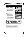
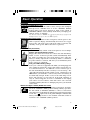
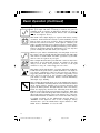
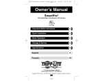
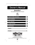
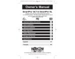
Owner's Manual
1111 W. 35th Street
Chicago, IL 60609 USA
Customer Support: (773) 869-1234
www.tripplite.com
SmartPro®
Datacenter INT
Intelligent, Line-Interactive
UPS Systems (230V Output)
Safety:
p. 2
Quick Installation:
Basic Operation:
p. 5 - 7
Storage & Service:
p. 8
Specifications:
p. 8
p. 3 - 4
Copyright ©2000 Tripp Lite. All rights reserved. SmartPro® is a registered trademark of Tripp Lite.
1
9905251 230V SmartPro Datacenter OM.p65 1
8/8/00, 2:02 PM
Safety
This manual contains important instructions and warnings that should be followed
during the installation, operation and storage of all Tripp Lite UPS Systems.
UPS Location Warnings
• Install your UPS indoors, away from excess moisture or heat, dust or
direct sunlight.
• For best performance, keep the indoor temperature between 0° C and
40° C (between 32° F and 104° F).
• Leave adequate space around all sides of the UPS for proper ventilation.
UPS Connection Warnings
• If your UPS has a corded input, connect it to a properly grounded AC
power outlet. Do not modify the UPS's plug. Do not use adapters that
eliminate the UPS's connection to ground.
• If your UPS has a hardwired input, ensure that it is properly grounded.
• Do not plug your UPS into itself; this will damage the UPS and void
your warranty.
• If you are connecting your UPS to a motor-powered AC generator,
the generator must provide clean, filtered computer-grade output.
Equipment Connection Warnings
• Do not use Tripp Lite UPS Systems for life support applications in
which a malfunction or failure of a Tripp Lite UPS System could cause
failure or significantly alter the performance of a life-support device.
• Do not connect surge suppressors to the output of your UPS. This
may damage your UPS and will void both the surge suppressor and
UPS warranties.
Battery Warnings
• Your UPS does not require routine maintenance. Do not open your
UPS for any reason. There are no user-serviceable parts inside.
• Battery replacement must be performed by qualified service personnel.
Because the batteries present a risk of electrical shock and burn from
high short-circuit current, qualified service personnel should observe
proper precautions: Unplug and turn off the UPS before performing
battery replacement. Use tools with insulated handles and replace the
existing batteries with the same number and type of new batteries
(Sealed Lead-Acid). Do not open the batteries. Do not short or bridge
the battery terminals with any object.
• The UPS batteries are recyclable. Refer to local codes for disposal
requirements, or in the US only call 1-800-SAV-LEAD for disposal
information. Do not dispose of the batteries in a fire.
• When adding external batteries, connect only Tripp Lite battery packs
of the correct voltage and type. Your UPS's External Battery Connector
should match the color of the connector of any battery pack you want
to connect.
2
9905251 230V SmartPro Datacenter OM.p65 2
8/8/00, 2:02 PM
Quick Installation
1
Position your External Battery
Pack(s).
• If positioning multiple Battery Packs, place them side
by side or stack them no more than three high.
2
Position your Power Module.
3
Plug your External Battery Pack
into your Power Module's
External Battery Connector on
its back panel.
• The Module may be stacked on top of your Battery
Packs or placed beside them.
BRANCH CIRCUIT #1
230VAC 10AMPS
00VA 4500W
M 50/60HZ 5000VA 3700W
50HZ 5000VA 3700W
CAUTION: DO NOT UNPLUG WHILE
OPERATING OR ARCING WILL OCCUR
36VDC 175 AMPS MAX
• For multiple Battery Packs, connect the first to the
Power Module, then daisy-chain the others: connect the
second to the first, the third to the second, and so on.
4
Plug your Power Module into a
L6-30 single-phase AC outlet on
a 30-amp dedicated circuit that
provides 220V to 240V at 50 Hz.
5
Plug your equipment into the
Power Module.
6
Turn your UPS ON.
• Set the System Switch on the UPS's back panel to the
“ENABLE” (RIGHT) position. (Figure 1a)
This switch activates the battery charger and microprocessor.
The “
” light will flash until you engage the ON/Standby
Switch to activate the “ON” mode.
BRANCH CIRCUIT #1
230VAC 10AMPS
50/60HZ 5000VA 4500W
30VAC NOM 50/60HZ 5000VA 3700W
0VAC NOM 50HZ 5000VA 3700W
CAUTION: DO NOT UNPLUG WHILE
OPERATING OR ARCING WILL OCCUR
36VDC 175 AMPS MAX
1a.
Back panel
• Engage the momentary ON/Standby Switch on the UPS's
front panel and release it to activate the “ON” mode and
supply power to the UPS receptacles. (Figure 2b)
2b.
Front panel
Communications on Next Page...
3
9905251 230V SmartPro Datacenter OM.p65 3
8/8/00, 2:02 PM
Computer Communications (Optional)*
1
DB9 Port Connection
–Optional–*
Using the grey or tan Tripp Lite cable
that came with your UPS, connect your
primary server’s DB9 port to the single
DB9 port labeled “LAN 4.1” or "Smart
LAN Primary" (which provides complete
intelligent RS-232 communications).**
2
CAUTION: DO NOT UNPLUG WHILE
OPERATING OR ARCING WILL OCCUR
36VDC 175 AMPS MAX
If you have additional
computers:
IN: 230VAC 50/60HZ 5000VA 4500W
OUT-LINE: 230VAC NOM 50/60HZ 5000VA 3700W
OUT-BAT: 230VAC NOM 50HZ 5000VA 3700W
a. Connect them to the DB9 ports
labeled “LAN 2.1” (which provide
basic, contact-closure shutdown
capabilities) using the black cables
that came with your UPS.
b. Set their corresponding LAN Interface
DIP Switches to the ACTIVATE (DOWN)
position. See diagram for which switch
controls which port.*** Note: the last
switch on the right has no function.
2a. Back panel
2b. Back Panel
3
Load software and run the installation program
appropriate for your operating system.
* Computer communications are optional. Your UPS will function properly without these connections.
** The “LAN 4.1” or "Smart" DB9 port is always enabled and is not controlled by the LAN Interface DIP Switches.
*** If you do not connect a computer to any of the “LAN 2.1” DB9 ports, set their corresponding LAN Interface DIP
Switches to the DEACTIVATE (UP) position.
4
9905251 230V SmartPro Datacenter OM.p65 4
8/8/00, 2:02 PM
CA
OPE
Basic Operation
Switches
System Switch (Middle Back Panel)
This switch activates the UPS's battery charger and intelligent
microprocessor. ALWAYS leave it in the “ENABLE” (RIGHT)
position when your UPS is plugged in. Only set the switch to
“DISABLE” (LEFT) to reduce battery drain when you unplug your
UPS for storage or shipping.
Note: When this switch is on "ENABLE", the “
” light will flash until you engage the ON/
Standby Switch to turn power ON at the UPS receptacles.
ON/Standby Switch (Front Panel)
This momentary switch on the front panel controls power to the
—
UPS receptacles. Engage it momentarily and release it to toggle
between the “ON” mode (power ON at the UPS receptacles) and
O
“Standby” mode (power OFF at the UPS receptacles).
Mute/Test Switch (Front Panel)
Use this momentary switch on the front panel to do two things:
Silence the UPS On Battery alarm
Engage this switch and release it to silence the UPS On Battery
alarm, a series of short beeps that sounds intermittantly when
the UPS is providing AC power from battery. Note: when the
battery is nearly depleted, the Low Battery alarm, a continuous
beep that cannot be silenced, will alert you to immediately shut
down connected equipment.
Test your UPS’s battery charge
Leave your connected equipment ON. With your UPS plugged in
and completely turned ON, engage this switch; hold it there for
5 seconds and release it. You will hear a series of short beeps as
the UPS momentarily switches to battery to test its charge. The
” light will turn ON and the alarm (a long, continuous beep)
“
will sound if your UPS fails a self-test and/or the UPS battery is
less than fully charged. If this occurs, let the UPS charge for 12
hours and perform a second self-test. If the light continues to
stay on, contact Tripp Lite for service. CAUTION: Do not unplug
your UPS to test its batteries. This will remove safe electrical
grounding and may introduce a damaging surge into your network
connections.
Maintenance Bypass Switch (Middle Rear Panel)
This switch, used during hot swap battery replacement, should be
left in the “NORMAL” (LEFT) position during ordinary operation.
Set this switch to “BYPASS” (RIGHT) to connect or disconnect
external battery packs while the UPS is plugged in and supporting
a load. The “
” light on the front panel will light to indicate that
battery backup protection is not available until this switch is
returned to the "NORMAL" (LEFT) position.
5
9905251 230V SmartPro Datacenter OM.p65 5
8/8/00, 2:02 PM
Basic Operation (Continued)
Indicator Lights
Light descriptions apply when the UPS is plugged into a wall outlet and turned ON.
This green light will shine constantly to indicate AC power is
available at the receptacles. It will flash to indicate AC power is
not available. (See “System Enable Switch” and “On/Standby
Switch” descriptions above.)
This multi-colored light displays 7 separate UPS battery charge
conditions. It will turn from red (low) to yellow (medium) to green
(full) to show you the level of battery charge remaining in both
internal and connected batteries. If the light is constant, your
UPS is operating from line power, and the battery is charging. If the
light is flashing, your UPS is operating from battery power, and the
battery is discharging. When the light flashes red, close any files
you are working on and shut down your computer.
Whenever your UPS is automatically correcting high or low AC
line voltage, this green light will turn ON and the UPS will gently
click. These are both normal, automatic operations of your UPS,
and no action is required on your part.
This red light will turn ON if your UPS fails a self-test and/or the
UPS battery is less than fully charged. If it lights, let the UPS
charge for 12 hours, then perform a self-test. If the light
continues to stay on, contact Tripp Lite for service.
This multi-colored light displays 4 separate UPS load conditions.
It will turn from green (low) to yellow (medium) to red (high) as
you connect equipment to show you the load level your UPS is
supporting. When the light is red, your UPS is supporting a load
above 85% of its capacity. If the red light begins flashing, then
your UPS is severely overloaded. Remove overload immediately
until light stops flashing.
This red light will turn ON when you set the Maintenance Bypass
Switch to “BYPASS”, indicating that the Power Module has turned
off its battery charger, allowing you to properly disconnect and
replace the Battery Packs. The light may also come on if Battery
Packs are improperly disconnected, indicating that the Power
Module is protecting itself from potential overvoltages. While this
light is on, the UPS will still provide filtered utility AC power and
will provide battery backup power if any batteries are connected.
DB9 communications are unaffected. To return the UPS's charger
to normal operation, set the Maintenance Bypass Switch to
“NORMAL”. If the light has come on due to improper battery
disconnection, cycle the Maintenance Bypass Switch to “BYPASS” then to “NORMAL” to reset the UPS.
6
9905251 230V SmartPro Datacenter OM.p65 6
8/8/00, 2:02 PM
Other UPS Features
AC Receptacles (Rear Panel)
These 230V IEC-320 receptacles provide your connected equipment
with AC line power during normal operation and battery power
during blackouts and brownouts. They also protect your equipment
against damaging surges and line noise. You can remotely reboot
connected equipment by turning receptacles OFF and ON using
Tripp Lite PowerAlert software.
Circuit Breakers (Rear Panel)
These breakers will trip to prevent damage to your UPS due to
overload. Two single-pole circuit breakers protect each 230V
outlet bank and one double-pole circuit breaker protects the main
input circuit bank that powers all the outlets. If a breaker trips,
remove any overload then allow the UPS to cool before resetting
the breaker.
"Smart" RS-232 Port (Lower Rear Panel)
This port, labeled “SMART LAN PRIMARY” or “LAN 4.1” on the
UPS, connects your UPS to a workstation or server. Use with Tripp
Lite software and cabling to monitor and manage network power
and to automatically save open files and shut down equipment
during power failures. This port uses RS-232 communications to
transmit UPS and power conditions (Pin 7 = Transmit; Pin 8 =
Common; Pin 9 = Receive). Contact Tripp Lite Customer Support
for more information and a list of available SNMP, network
management and connectivity products.
Contact Closure Ports (Lower Rear Panel)
These ports, labeled “LAN 2.2” on the Control Module, are also
used to connect your UPS to a workstation or server. Use with
Tripp Lite software and cabling to automatically save open files
and shut down equipment during a blackout. This port uses
contact-closure signals to indicate line-fail and low-battery
status. Contact Tripp Lite Customer Support for more information.
Battery Connector (Rear Panel)
Use to connect Tripp Lite battery packs. Refer to the label next to
the connector for the appropriate Tripp Lite battery pack to
connect. Refer to instructions available with the battery pack for
complete connection information and safety warnings.
Remote Control Interface Port (Lower Rear Panel)
Use to connect an optional RT-2 Remote Control Adapter to
control the DataCenter via telephone or modem. Contact Tripp
Lite for information about ordering the RT-2; refer to the RT-2
manual for operating instructions.
7
9905251 230V SmartPro Datacenter OM.p65 7
8/8/00, 2:02 PM
Storage & Service
Storage
Turn your UPS OFF: first engage the ON/Standby Switch and release it to place
your UPS in the “Standby” mode, then move the System Enable Switch to the
“DISABLE” (DOWN) position to prevent battery drain, then disconnect the UPS
power cord from the wall outlet. If you plan on storing your UPS for an extended
period of time, recharge the UPS batteries once every three months. Follow
steps #3 and #4 in the Quick Installation section and allow the UPS to charge
until the “ ” light glows green (may take 6 or more hours depending on the
number of batteries connected). If you leave your UPS batteries discharged for
an extended period of time, they may suffer permanent loss of capacity.
Service
If returning your UPS for service, contact your local Tripp Lite dealer or
distributor. They will refer you to a service center. Please carefully pack the UPS
using the ORIGINAL PACKING MATERIAL that came with the unit. Enclose a
letter describing the symptoms of the problem. If the UPS is within the 2 year
warranty period, enclose a copy of your sales receipt.
Specifications
SMARTDC3000INT
Output Capacity (VA/Watts):
3000/2400
Battery Runtime (with Battery Pack) (with 1 BP36V33*)
for Half Load/Full Load in Minutes:
26+/11+†
Battery Recharge Time:
2-4 hrs.
Approvals:
—
SMARTDC5000INT
Output Capacity (VA/Watts):
5000/3750
Battery Runtime (with Battery Pack) (with 1 BP36V33*)
for Half Load/Full Load in Minutes:
42+/18+†
Battery Recharge Time:
2-4 hrs.
Approvals:
SASO
SMARTDC3000XRINT
3000/2400
(with 1 BP36VXR*)
84+/36+†
2-4 hrs.
—
SMARTDC5000XLINT
5000/3750
(with 2 BP36V33*)
108+/42+†
2-4 hrs.
SASO
* Included with UPS.
† Battery Runtime can be increased by adding additional external battery packs. This will increase recharge time, however.
Input Voltage (220-240V); Input Frequency (50 Hz); On-Line Input Voltage Range (166-276 volts); Voltage-Regulated Output Voltage
Range (220/240V +8%/-15%); On-Battery Output Voltage Range (220/240V ± 5%); Output Waveform Line Mode (filtered sinewave); Output
Waveform Battery Mode (PWM sine wave); AC Surge Suppression (exceeds IEEE 587 Cat. A & B standards);
AC Noise Attenuation (>40 dB); AC TVSS Protection Modes (H to N, H to G, N to G).
The policy of Tripp Lite is one of continuous improvement. Specifications are subject to change.
93-1417 (9905251) 0800
8
9905251 230V SmartPro Datacenter OM.p65 8
8/8/00, 2:02 PM