1
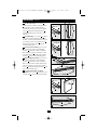
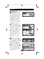
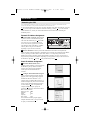
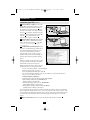
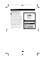
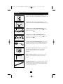
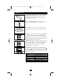
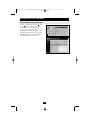
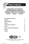
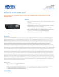
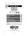
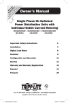
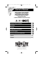
200707133 93-2718 PDUMH15-20HVNET OM.qxd
9/7/2007
11:13 AM
Page 1
e
nc
a t!
ty n a ch oduc
n
r
o
r
ra ti fo p nty
ar tra day Lite arra
W is e to ripp /w
g lin T om
Re r on REE lite.c
e F pp
st
i
gi in a .tr
e
R w ww
to w
Owner’s Manual
PDUMH15HVNET
PDUMH20HVNET
Switched Rack PDU
• 208/230V, 50/60Hz AC Input and Output
Important Safety Instructions
2
Installation
2
Features
8
Configuration and Operation
10
Technical Support
11
Warranty and Warranty Registration
11
Español
12
Français
23
1111 W. 35th Street • Chicago, IL 60609 USA
(773) 869-1234 • www.tripplite.com
Copyright © 2007 Tripp Lite. All rights reserved.
200707133 93-2718 PDUMH15-20HVNET OM.qxd
9/7/2007
11:13 AM
Page 2
Important Safety Instructions
SAVE THESE INSTRUCTIONS
This manual contains instructions and warnings that should be
followed during the installation, operation, and storage of this product.
Failure to heed these instructions and warnings will void the product
warranty.
• The PDU provides convenient multiple outlets, but it DOES NOT provide surge or line noise
protection for connected equipment.
• The PDU is designed for indoor use only in a controlled environment away from excess moisture,
temperature extremes, conductive contaminants, dust or direct sunlight.
• Do not connect the PDU to an ungrounded outlet or to extension cords or adapters that eliminate
the connection to ground.
• The power requirement for each piece of equipment connected to the PDU must not exceed the
individual outlet’s load rating.
• The total power requirement for equipment connected to the PDU must not exceed the maximum
load rating for the PDU.
• Do not drill into or attempt to open any part of the PDU housing. There are no user-serviceable
parts inside.
• Do not attempt to modify the PDU, including the input plugs and power cables.
• Do not attempt to use the PDU if any part of it becomes damaged.
• Do not attempt to mount the PDU to an insecure or unstable surface.
• Never attempt to install electrical equipment during a thunderstorm.
• Use of this equipment in life support applications where failure of this equipment can reasonably
be expected to cause the failure of the life support equipment or to significantly affect its safety or
effectiveness is not recommended. Do not use this equipment in the presence of a flammable
anesthetic mixture with air, oxygen or nitrous oxide.
Installation
Mounting the PDU
The PDU supports five primary mounting configurations: 1U Rack, 0U Rack (Vertical), Wall, UnderCounter and Reduced-Depth.
Note: Regardless of configuration, the user must determine the fitness of hardware and procedures before mounting. The PDU and
included hardware are designed for common rack and rack enclosure types and may not be appropriate for all applications. Exact
mounting configurations may vary. Screws for attaching the mounting brackets and cord retention shelf to the PDU are included. Use
only the screws supplied by the manufacturer, or their exact equivalent (#6-32, ¼" flat head).
1-1 1U Rack Mounting: Use 4 screws A to
attach each of the 2 longer mounting brackets B
to the PDU as shown. You can mount the PDU
in a recessed position by attaching the mounting
brackets so they extend beyond the front panel
of the PDU. (If you plan to use the cord
retention shelf, attach the mounting brackets in a
recessed position.) Mount the PDU in the rack
by inserting 4 user-supplied screws C through
the mounting brackets D and into the mounting
holes of the rack rails.
A
A
B
D
1-1
2
C
200707133 93-2718 PDUMH15-20HVNET OM.qxd
Installation
9/7/2007
11:13 AM
Page 3
continued
1-2 0U Rack Mounting: Use 4 screws A to
attach each of the 2 shorter mounting brackets
B to the PDU as shown. Mount the PDU
vertically by inserting 2 or more user-supplied
screws C through the mounting brackets D
and into mounting points in the rack or rack
enclosure.
B
D
C
D
C
A
1-3 Wall Mounting: Use 4 screws A to attach
each of the 2 shorter mounting brackets B to
the PDU as shown. Mount the PDU to the wall
by inserting 2 or more user-supplied screws C
through the mounting brackets D and into
secure mounting points.
1-2
B
1-4 Under-Counter Mounting: Use 4 screws
A to attach each of the 2 shorter mounting
brackets B to the PDU as shown. Mount the
PDU under the counter by inserting 2 or more
user-supplied screws C through the mounting
brackets D and into secure mounting points.
A
1-3
1-5 Reduced-Depth Mounting: Use 4 screws
A to attach each of the 2 shorter mounting
brackets B to the PDU as shown. Mount the
PDU to a stable surface with the outlets facing
upward by inserting 2 or more user-supplied
screws C through the mounting brackets D and
into secure mounting points.
B
A
D
1-6 Cord Retention Shelf Attachment
(Optional): Use 2 screws A to attach the cord
retention shelf B to the front panel of the PDU.
C
1-4
D
B
C
A
1-5
B
1-6
3
A
200707133 93-2718 PDUMH15-20HVNET OM.qxd
Installation
9/7/2007
11:13 AM
Page 4
continued
Connecting the PDU
2-1 NEMA Adapter Connection (Optional PDUMH20HVNET Only): The
PDUMH20HVNET includes a plug adapter that
adds a NEMA L6-20P plug to the input power
cord. Use this adapter only if you will be
connecting the PDUMH20HVNET to a NEMA
L6-20R outlet. Insert the IEC 60320 C19
connector A of the adapter into the IEC 60320
C20 connector B of the input power cord.
Secure the connection with the retention
bracket C by using the included bolts to fasten
the two halves of the bracket around the
connection as shown. Caution: To avoid the
risk of electric shock, ensure that the Neutral
(L2) conductor has been identified before
connecting the PDU.
C
A
B
2-1
2-2 Input Power Cord Connection: Insert the
IEC 60320 C19 (PDUMH20HVNET) or IEC
60320 C13 (PDUMH15HVNET) connector A
of the input power cord into the IEC 60320 C20
(PDUMH20HVNET) or IEC 60320 C14
(PDUMH15HVNET) inlet B of the PDU.
Connect the other end of the input power cord
C to a compatible source of AC power, such as
a UPS system, PDU or utility outlet. The PDU
should be provided with over-current
protection: PDUMH20HVNET should be
provided with a maximum 20A branch-rated
over-current protection device;
PDUMH15HVNET should be provided with a
maximum 15A branch-rated over-current
protection device.
88
B
C
A
PDUMH15HVNET
B
88
A
C
2-2
PDUMH20HVNET
Note: The AC power source should not share a circuit with a
heavy electrical load (such as an air conditioner or
refrigerator).
2-3 Equipment Power Cord Connection:
Insert the IEC 60320 C14 connectors A of the
equipment power cords into the IEC 60320 C13
output receptacles B of the PDU. The LED C
near each output receptacle illuminates when
the receptacle is ready to distribute live AC
power. The digital load meter D will display
the total connected equipment load in amps.
2-4 Cord Retention (Optional): If you
attached the cord retention shelf in step 1-6 ,
tie the input power cord and each equipment
power cord to the retention shelf. Attach each
cord to the retention shelf by looping the cord
and securing it to an attachment point with one
of the included cable ties. Make sure that each
cord can be unplugged from the PDU without
removing the cable tie.
B
15
2-3
A
D
C
15
2-4
4
200707133 93-2718 PDUMH15-20HVNET OM.qxd
Installation
9/7/2007
11:13 AM
Page 5
continued
Networking the PDU
Note: The MAC address of the PDU (a 12-digit string in this format: 000667xxxxxx) is printed on a label attached to the PDU
enclosure. The MAC address is also printed on a label attached to the internal network card.
If your network's DHCP server will assign a dynamic IP address to the PDU automatically, go to Step
4-1 . If you will assign a static IP address to the PDU manually, go to Step 5-1 . If you are uncertain
which method to use, contact your network administrator for assistance before continuing the
installation process.
Dynamic IP Address Assignment
4-1 Connect PDU to Network: While the PDU
is powered, connect a standard Ethernet patch
cable to the RJ-45 Ethernet port A on the PDU.
Note: This port is not compatible with PoE
(Power over Ethernet) applications. The PDU
will attempt to obtain an IP address via DHCP.
This may take as long as several minutes,
depending on your network environment.
A
15
4-1
4-2 Discover IP Address: Contact your network administrator to determine which dynamic IP
address has been assigned to the PDU by the DHCP server. The PDU can be identified on the DHCP
server by referring to its MAC address. (The MAC address is a 12-digit string in this format:
000667xxxxxx. Refer to the MAC address label attached to the PDU.) You may wish to request a
long-term lease period for the IP address, depending on your application. After you have discovered
the IP address, skip Steps 5-1 through 5-6 and proceed directly to Step 6-1 .
Static IP Address Assignment
5-1 Determine IP Information: Before
assigning a static IP address, you'll need to know
the IP address, gateway address and subnet
mask. If you do not have this information,
contact your network administrator for
assistance.
A
5-2 Configure Terminal Emulation Program:
Open a VT100-compatible terminal emulation
program (such as the HyperTerminal program
bundled with Microsoft® Windows®) on a
computer with an available DB9 serial port. (A
notebook computer may be the most convenient
choice.) Set the terminal emulation program to
use the COM port A that corresponds to the
computer’s DB9 serial port. Specify the
parameters B required to communicate with the
PDU terminal interface:
Bits per second:
Data bits:
Parity:
Stop bits:
Flow control:
B
9600
8
None
1
None
If the terminal emulation program supports
multiple emulation modes, you may also need
to specify VT100 emulation C .
C
5
200707133 93-2718 PDUMH15-20HVNET OM.qxd
Installation
9/7/2007
11:13 AM
Page 6
continued
Networking the PDU
continued
5-3 Connect PDU to Computer: Use the miniDIN to DB9 serial cable (part number 73-1025)
included with the PDU to connect the PDU to
the computer. The circular connector A at one
end of the cable attaches to the 8-pin mini-DIN
serial port B on the PDU. (Align the connector
carefully to avoid damaging the pins.) The DB9
connector C at the other end of the cable
connects to the computer's serial port D .
B
C
A
5-3
D
A
5-4 Connect PDU to Network: While the PDU
is powered, connect a standard Ethernet patch
cable to the RJ-45 Ethernet port A on the PDU.
Note: This port is not compatible with PoE (Power over
Ethernet) applications.
5-4
5-5 Configure PDU in Terminal Mode: After a
brief pause, an initialization page should appear
in the terminal emulation program. Press any
key on the keyboard within 10 seconds to
change the PDU settings. (If the 10-second
period has elapsed, you can reboot the PDU by
powering down completely and then restoring
power.)
Follow the sequence of responses below in order
to assign an IP address to the PDU. The default
5-5
terminal mode root password is TrippLite.
Sample IP settings are shown - supply your own
IP information when you configure your PDU.
Press A to Accept the settings, or M to Modify? M
Enter the root password: *********
Reset configuration to default values (Y/N)? N
For each of the following questions, you can press <Return> to select the value shown in
braces, or you can enter a new value.
NETWORK INTERFACE PARAMETERS:
Should this target obtain IP settings from the network?[N] N
Static IP address [192.168.1.19]? 192.168.0.123
Static IP address is 192.168.0.123
Subnet Mask IP address [255.255.0.0]? 255.255.255.0
Subnet Mask IP address is 255.255.255.0
Gateway address IP address [192.168.1.1]? 192.168.0.1
Gateway address IP address is 192.168.0.1
You can also change the root password, real-time clock and other settings. (Tripp Lite recommends
against changing the default settings unless you are an advanced user with a specific purpose.) After
you have finished entering settings, the PDU will save changes to memory and reboot (this may take
several minutes). After the PDU reboots, the initialization page should display the new static IP
settings.
5-6 Remove Serial Cable: Remove the serial cable from the PDU and proceed to Step
6
6-1 .
200707133 93-2718 PDUMH15-20HVNET OM.qxd
Installation
9/7/2007
continued
Networking the PDU
continued
Testing Network Connection
6-1 Access PDU with Web Browser: After an
IP address has been assigned to the PDU,
attempt to access it with a Web browser that
supports frames, forms and Java™. Open a Web
browser on a computer connected to the LAN
and enter the IP address assigned to the PDU.
You should be prompted for a password A . The
user name is admin and the default password is
admin. After you enter the user name and
password, the PowerAlert Status page B will
appear in the browser window. For more
information about configuration and operation of
the PDU via the PowerAlert interface, refer to
the SNMPWEBCARD User's Guide, included
on the CD-ROM bundled with the PDU.
A
Note for Network Management System Users Only: Two MIB
files - Tripplite.mib and RFC1628.mib - must be loaded on each
Network Management Station that will monitor the PDU via
SNMP. The files are provided on the CD-ROM included in the
product package.
B
7
11:13 AM
Page 7
200707133 93-2718 PDUMH15-20HVNET OM.qxd
9/7/2007
11:13 AM
Page 8
Features
AC Input Power Inlet (Model PDUMH15HVNET): The IEC
60320 C14 inlet connects to the detachable AC Input Power Cord.
AC Input Power Inlet (Model PDUMH20HVNET): The IEC
60320 C20 inlet connects to the detachable AC Input Power Cord.
A
B
A
B
AC Input Power Cord (Model PDUMH15HVNET): The
detachable cord has an IEC 60320 C13 connector A and an IEC
60320 C14 connector B .
AC Input Power Cord (Model PDUMH20HVNET): The
detachable cord has an IEC 60320 C19 connector A and an IEC
60320 C20 connector B .
AC Input Adapter (Model PDUMH20HVNET): The adapter
converts the AC input power cord to a NEMA L6-20P plug. The
included retention bracket (not shown) secures the connection.
IEC 60320 C13 Output Receptacles: During normal operation,
the output receptacles distribute AC power to connected
equipment. When an outlet is live, the associated LED
illuminates.
Digital Load Meter (Ammeter): The total electrical current
drawn by connected equipment is displayed on the meter in
amperes.
Cord Retention Shelf: When it is attached to the PDU, the cord
retention shelf provides secure attachment points for the input
cord and connected equipment cords. Use the included cable ties
to secure the cords to the shelf.
8
200707133 93-2718 PDUMH15-20HVNET OM.qxd
Features
9/7/2007
11:13 AM
Page 9
continued
Longer Mounting Brackets: Use these brackets to mount the
PDU horizontally in a standard rack or rack enclosure. The
mounting depth can be adjusted by attaching the brackets to
different positions on the PDU.
Shorter Mounting Brackets: Use these brackets to mount the
PDU in a 0U rack, wall or under-counter configuration.
Factory Port: The port is reserved for configuration by factory
authorized personnel only. Do not connect anything to the port.
PS/2 Port: Use this port to connect a Tripp Lite ENVIROSENSE
environmental sensor to provide remote temperature/humidity
monitoring and a dry contact interface to control and monitor
alarm, security and telecom devices. Contact Tripp Lite Customer
Support at (773) 869-1234 for ordering information. Note: Do not
connect a keyboard or mouse to this port.
Mini-DIN Serial Port: Use this port to provide a direct terminal
connection to a computer with a terminal emulation program. A
serial cable (part number 73-1025) is included with the PDU. If
you need to order a replacement cable, contact Tripp Lite
Customer Support at (773) 869-1234.
A
B
Ethernet Port: Use this RJ-45 jack to connect the PDU to the
network with a standard Ethernet patch cable. The Link LED A
and Status LED B indicate several operating conditions, as shown
in the table below. This port is not compatible with PoE (Power
Over Ethernet) applications.
Network Operating Conditions
A Link LED Color
Off
Flashing Amber
Flashing Green
B Status LED Color
Off
Steady Green
Flashing Amber
9
No Network Connection
100 Mbps Network Connection
10 Mbps Network Connection
Card Not Initialized
Card Initialized and Operational
Error - Card Not Initialized
200707133 93-2718 PDUMH15-20HVNET OM.qxd
9/7/2007
Configuration and Operation
Remote Monitoring and Control
The PDU provides remote monitoring A , outlet
control B and more via Web browser, telnet
and SNMP-based Network Management
Systems. For more information about
configuration and operation of the PDU via the
PowerAlert Web browser interface, refer to the
SNMPWEBCARD User's Guide, included on
the CD-ROM bundled with the PDU.
A
B
10
11:13 AM
Page 10
200707133 93-2718 PDUMH15-20HVNET OM.qxd
9/7/2007
11:13 AM
Page 11
Technical Support
Telephone: (773) 869-1233
8:00 AM - 6:00 PM CST Monday - Thursday
8:00 AM - 5:30 PM CST Friday
(CST is Central Standard Time in the United States.)
E-mail: [email protected]
Warranty and Warranty Registration
LIMITED WARRANTY
Seller warrants this product, if used in accordance with all applicable instructions, to be free from original defects in material
and workmanship for a period of 2 years (except internal UPS system batteries outside USA and Canada, 1 year) from the
date of initial purchase. If the product should prove defective in material or workmanship within that period, Seller will repair
or replace the product, in its sole discretion. Service under this Warranty can only be obtained by your delivering or shipping
the product (with all shipping or delivery charges prepaid) to: Tripp Lite, 1111 W. 35th Street, Chicago, IL 60609 USA. Seller
will pay return shipping charges. Call Tripp Lite Customer Service at (773) 869-1234 before sending any equipment back for
repair.
THIS WARRANTY DOES NOT APPLY TO NORMAL WEAR OR TO DAMAGE RESULTING FROM ACCIDENT, MISUSE,
ABUSE OR NEGLECT. SELLER MAKES NO EXPRESS WARRANTIES OTHER THAN THE WARRANTY EXPRESSLY SET
FORTH HEREIN. EXCEPT TO THE EXTENT PROHIBITED BY APPLICABLE LAW, ALL IMPLIED WARRANTIES,
INCLUDING ALL WARRANTIES OF MERCHANTABILITY OR FITNESS, ARE LIMITED IN DURATION TO THE WARRANTY
PERIOD SET FORTH ABOVE; AND THIS WARRANTY EXPRESSLY EXCLUDES ALL INCIDENTAL AND CONSEQUENTIAL
DAMAGES. (Some states do not allow limitations on how long an implied warranty lasts, and some states do not allow the
exclusion or limitation of incidental or consequential damages, so the above limitations or exclusions may not apply to you.
This Warranty gives you specific legal rights, and you may have other rights which vary from jurisdiction to jurisdiction).
WARNING: The individual user should take care to determine prior to use whether this device is suitable, adequate or safe for
the use intended. Since individual applications are subject to great variation, the manufacturer makes no representation or
warranty as to the suitability or fitness of these devices for any specific application.
WARRANTY REGISTRATION
Visit www.tripplite.com/warranty today to register the warranty for your new Tripp Lite product. You'll be automatically entered
into a drawing for a chance to win a FREE Tripp Lite product!*
* No purchase necessary. Void where prohibited. Some restrictions apply. See website for details.
FCC Notice
This device complies with part 15 of the FCC Rules. Operation is subject to the following two conditions: (1) This device may
not cause harmful interference, and (2) this device must accept any interference received, including interference that may
cause undesired operation.
This equipment has been tested and found to comply with the limits for a Class A digital device, pursuant to part 15 of the
FCC Rules. These limits are designed to provide reasonable protection against harmful interference when the equipment is
operated in a commercial environment. This equipment generates, uses, and can radiate radio frequency energy and, if not
installed and used in accordance with the instruction manual, may cause harmful interference to radio communications.
Operation of this equipment in a residential area is likely to cause harmful interference in which case the user will be required
to correct the interference at his own expense. The user must use shielded cables and connectors with this product. Any
changes or modifications to this product not expressly approved by the party responsible for compliance could void the user's
authority to operate the equipment.
Regulatory Compliance Identification Numbers
For the purpose of regulatory compliance certifications and identification, your Tripp Lite product has been assigned a unique
series number. The series number can be found on the product nameplate label, along with all required approval markings
and information. When requesting compliance information for this product, always refer to the series number. The series
number should not be confused with the marking name or model number of the product.
The policy of Tripp Lite is one of continuous improvement. Specifications are subject to change without notice.
11