1
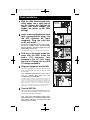
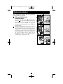
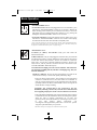
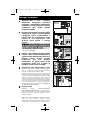
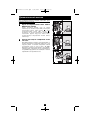
201112134 93-3152.qxd 1/18/2012 2:16 PM Page 1 Owner’s Manual SmartPro® SLT Intelligent, Line-Interactive UPS System • 220/230/240V Pure Sine Wave Input/Output Agency Models AG-0020, AG-0021, AG-0022 Not suitable for mobile applications. Important Safety Instructions 2 Quick Installation 3 Optional Installation 4 Basic Operation 5 Battery Replacement 8 Storage and Service 8 Español 9 Français 17 Deutsch 25 33 1111 W. 35th Street, Chicago, IL 60609 USA www.tripplite.com/support Copyright © 2012 Tripp Lite. All rights reserved. SmartPro® is a trademark of Tripp Lite 201112134 93-3152.qxd 1/18/2012 2:16 PM Page 2 Important Safety Instructions SAVE THESE INSTRUCTIONS This manual contains important instructions that should be followed during the installation, operation and storage of all Tripp Lite UPS Systems. Failure to heed these warnings may affect your warranty. UPS Location Warnings • Use caution when lifting UPS. • Install your UPS indoors, away from excess moisture or heat, dust or direct sunlight. • For best performance, the ambient temperature near your UPS should be between 0° C and 40° C (between 32° F and 104° F). • Leave adequate space around all sides of the UPS for proper ventilation. Do not obstruct its vents or fan openings. • Do not mount unit with its front or rear panel facing down (at any angle). Mounting in this manner will seriously inhibit the unit's internal cooling, eventually causing product damage not covered under warranty. UPS Connection Warnings • The UPS contains its own energy source (battery). The output terminals may be live even when the UPS is not connected to an AC supply. • Connect your UPS to a properly grounded AC power outlet. Do not modify the UPS’s plug in a way that would eliminate the UPS’s connection to ground. Do not use adapters that eliminate the UPS’s connection to ground. • Do not plug your UPS into itself; this will damage the UPS and void your warranty. • If you are connecting your UPS to a motor-powered AC generator, the generator must provide filtered, frequency-regulated computer-grade output. Equipment Connection Warnings • Use of this equipment in life support applications where failure of this equipment can reasonably be expected to cause the failure of the life support equipment or to significantly affect its safety or effectiveness is not recommended. Do not use this equipment in the presence of a flammable anesthetic mixture with air, oxygen or nitrous oxide. • Do not connect surge suppressors or extension cords to the output of your UPS. This might overload the UPS and will void the surge suppressor and UPS warranties. Battery Warnings • Batteries can present a risk of electrical shock and burn from high short-circuit current. Observe proper precautions. Do not dispose of the batteries in a fire. Do not open the UPS or batteries. Do not short or bridge the battery terminals with any object. Unplug and turn off the UPS before performing battery replacement. Use tools with insulated handles. There are no user-serviceable parts inside the UPS. Battery replacement should be performed only by authorized service personnel using the same number and type of batteries (Sealed Lead-Acid). The batteries are recyclable. Refer to your local codes for disposal requirements or visit www.tripplite.com/UPSbatteryrecycling for recycling information. Tripp Lite offers a complete line of UPS System Replacement Battery Cartridges (R.B.C.).Visit Tripp Lite on the Web at www.tripplite.com/support/battery/index.cfm to locate the specific replacement battery for your UPS. 2 201112134 93-3152.qxd 1/18/2012 2:16 PM Page 3 Quick Installation 1 2 With the UPS disconnected from utility power, use a small tool to set the Voltage Dip Switches to match your input voltage. (All models are preset to the 230V setting.) SMX750SLT, SMX1050SLT & SMX1500SLT 1 Insert a user-supplied power cord (with country-specific plug) into the UPS System's AC input receptacle. Plug the cord into an AC wall outlet. NOTE! after you plug the UPS into a live AC outlet, the UPS (in “Standby” mode) will automatically charge its batteries,* but will not supply power to its outlets until it is turned ON. 2 * The BATTERY CHARGE LED will be the only LED illuminated. 3 4 Find one of the power cords that came with the UPS. Insert the cord's C13 connector into computer's C14 AC inlet. Insert the cord's C14 plug into any UPS C13 output receptacle. Plug your equipment into the UPS. Plug your equipment into the UPS. Repeat Step 3 above using the additional power cord(s) that came with the UPS. Note: Additional interconnection cords (C13 to C14) are available from Tripp Lite. Call 773-869-1234 (Part # P004-006). Your UPS is designed to support computer equipment only. You will overload the UPS if the total VA ratings for all the equipment you connect exceeds UPS output capacity. To find your equipment’s VA ratings, look on their nameplates. If the equipment is listed in amps, multiply the number of amps by 240 to determine VA. (Example: 1 amp × 240 = 240 VA). If you are unsure if you have overloaded your UPS's outlets, see “OUTPUT LOAD LEVEL” LED description. 5 3 Turn the UPS ON. Press and hold the “ON/OFF/STANDBY” button for one second. The alarm will beep once briefly after one second has passed. Release the button. Note: UPS system will function properly upon initial startup; however, maximum runtime for the unit's battery will only be accessible after it has been charged for 24 hours. 3 4 5 240V 230V 220V 230V 201112134 93-3152.qxd 1/18/2012 2:16 PM Page 4 Optional Installation These connections are optional. Your UPS will function properly without these connections. 1 USB and RS-232 Serial Communications Use the included USB cable (see 1a ) and/or DB9 serial cable (see 1b ) to connect the communication port on your computer to the communication port of your UPS. Install on your computer the Tripp Lite PowerAlert Software appropriate to your computer’s operating system. 2 1a Telephone/Network Protection Jacks Your UPS has jacks that protect against surges over a telephone line or a network dataline. Using telephone or network data cables, connect your wall jack to the UPS jack marked “IN.” Connect your equipment to the UPS jack marked “OUT.” Make sure the equipment you connect to the UPS's jacks is also protected against surges on the AC line. 1b 2 4 201112134 93-3152.qxd 1/18/2012 2:16 PM Page 5 Basic Operation Buttons (Front Panel) “ON/OFF/STANDBY” Button • To turn the UPS ON: with the UPS plugged into a live AC wall outlet*, press and hold the “ON/OFF/STANDBY” button for one second.** Release the button. If utility power is absent, you can “cold-start” the UPS (i.e.: turn it ON and supply power for a limited time from its batteries***) by pressing and holding the “ON/OFF/STANDBY” button for one second.** • To turn the UPS OFF: with the UPS ON and receiving utility power, press and hold the “ON/OFF/STANDBY” button for one second.** Then unplug the UPS from the wall outlet. The UPS will be completely OFF. * After you plug the UPS into a live AC outlet, the UPS (in ”Standby” mode) will automatically charge its batteries, but will not supply power to its outlets until it is turned ON. ** The alarm will beep once briefly after the indicated interval has passed. *** If fully charged. “MUTE/TEST” Button To Silence (or “Mute”) UPS Alarms: briefly press and release the MUTE/TEST button.* To Run a Self-Test: with your UPS plugged in and turned ON, press and hold the MUTE/TEST button. Continue holding the button until the alarm beeps several times and the UPS performs a self test. See “Results of a Self-Test” below. Note: you can leave connected equipment on during a self-test. Your UPS, however, will not perform a self-test if the UPS is not turned on (see “ON/OFF/STANDBY” Button description). CAUTION! Do not unplug your UPS to test its batteries. This will remove safe electrical grounding and may introduce a damaging surge into your network connections. Results of a Self-Test: The test will last approximately 10 seconds as the UPS switches to battery to test its load capacity and battery charge. • If the “OUTPUT LOAD LEVEL” LED remains lit red and the alarm continues to sound after the test, the UPS’s outlets are overloaded. To clear the overload, unplug some of your equipment and run the self-test repeatedly until the “OUTPUT LOAD LEVEL” LED is no longer lit red and the alarm is no longer sounding. CAUTION! Any overload that is not corrected by the user immediately following a self-test may cause the UPS to shut down and cease supplying output power in the event of a blackout or brownout. • If the “BATTERY WARNING” LED remains lit and the alarm continues to sound after the test, the UPS batteries need to be recharged or replaced. Allow the UPS to recharge continuously for 12 hours, and repeat the self-test. If the LED remains lit, contact Tripp Lite for service. If your UPS requires battery replacement, visit www.tripplite.com/support/battery/index.cfm to locate the specific Tripp Lite replacement battery for your UPS. * The alarm will beep once briefly after the indicated interval has passed. 5 201112134 93-3152.qxd 1/18/2012 2:16 PM Page 6 Basic Operation continued Indicator Lights (Front Panel) All Indicator Light descriptions apply when the UPS is plugged into a wall outlet and turned ON. “POWER” LED: this green LED lights continuously when the UPS is ON and supplying connected equipment with AC power from a utility source. The LED flashes and an alarm sounds (4 short beeps followed by a pause) to indicate the UPS is operating from its internal batteries during a blackout or severe brownout. If the blackout or severe brownout is prolonged, you should save files and shut down your equipment since internal battery power will eventually be depleted. See “BATTERY CHARGE” LED description below. “VOLTAGE CORRECTION” LED: this green LED lights continuously whenever the UPS is automatically correcting high or low AC voltage on the utility line without the assistance of battery power. The UPS will also emit a slight clicking noise. These are normal, automatic operations of the UPS, no action is required on your part. “OUTPUT LOAD LEVEL” LEDs: the LEDs indicate the approximate electrical load of equipment connected to the UPS's AC outlets. They will turn from green (light load) to yellow (medium load) to red (overload). If the LED is red (either illuminated continuously or flashing), clear the overload immediately by unplugging some of your equipment from the outlets until the LED changes from red to yellow (or green). CAUTION! Any overload that is not corrected by the user immediately may cause the UPS to shut down and cease supplying output power in the event of a blackout or brownout. “BATTERY CHARGE” LEDs: when the UPS is operating from utility power, the LEDs indicate the approximate charge state of the UPS's internal batteries: red indicates the batteries are beginning to charge; yellow indicates the batteries are roughly midway through charging; and green indicates the batteries are fully charged. When the UPS is operating from battery power during a blackout or severe brownout, the LEDs indicate the approximate amount of energy (ultimately affecting runtime) which the UPS’s batteries will provide: red indicates a low level of energy; yellow indicates a medium level of energy; and green indicates a high level of energy. Since the runtime performance of all UPS batteries will gradually deplete over time, it is recommended that you periodically perform a self-test (see MUTE/TEST Button description) to determine the energy level of your UPS batteries BEFORE a blackout or severe brownout occurs. During a prolonged blackout or severe brownout, you should save files and shut down your equipment since battery power will eventually be depleted. When the red LED illuminates and an alarm sounds continuously, it indicates the UPS's batteries are nearly out of power and UPS shutdown is imminent. “BATTERY WARNING” LED: this LED lights red and an alarm sounds intermittently after you initiate a self test (See “MUTE/TEST” Button description) to indicate the UPS batteries need to be recharged or replaced. Allow the UPS to recharge continuously for 12 hours, and repeat the self-test. If the LED continues to light, contact Tripp Lite for service. If your UPS requires battery replacement, visit www.tripplite.com to locate the specific Tripp Lite replacement battery for your UPS. 6 201112134 93-3152.qxd 1/18/2012 2:16 PM Page 7 Basic Operation continued Other UPS Features (Rear Panel) AC Receptacles: Your UPS features IEC-320-C13 outlets. These output receptacles provide your connected equipment with AC line power during normal operation and battery power during blackouts and brownouts. The UPS protects equipment connected to these receptacles against damaging surges and line noise. Communications Ports (USB or RS-232): These ports connect your UPS to any workstation or server. Use with Tripp Lite’s PowerAlert Software and included cables to enable your computer to automatically save open files and shut down equipment during a blackout. Also use PowerAlert Software to monitor a wide variety of AC line power and UPS operating conditions. Consult your PowerAlert Software manual or contact Tripp Lite Customer Support for more information. See “USB and RS-232 Serial Communications” in the “Optional Installation” section for installation instructions. Telephone/Network Protection Jacks: These jacks protect your equipment against surges over a telephone/network data line. Connecting your equipment to these jacks is optional. Your UPS will work properly without this connection. 240V 230V 220V 230V Voltage DIP Switches: These switches enable the UPS to be set to match actual input voltage. If the Voltage DIP Switches are set above or below input voltage, the UPS will treat the input as a continuous overvoltage or undervoltage condition, and will automatically adjust input voltage to match the Voltage DIP Switch setting. This will cause constant, unnecessary wear on the UPS. Note: The Voltage DIP Switches must be set with the UPS turned OFF and disconnected from utility power. If the switches are set while the UPS is connected to utility power, the setting will not take effect. Accessory Slot: Remove the small cover panel from this slot to install optional accessories to remotely monitor and control your UPS. Refer to your accessory’s manual for installation instructions. Contact Tripp Lite Customer Support at (773) 869-1234 for more information, including a list of available SNMP, network management and connectivity products. Input Breaker (SMX1500SLT): Protects your electrical circuit from overcurrent draw from the UPS load. If this breaker trips, remove some of the load, then reset by pressing the breaker in. Fan: The fan cools the UPS's internal components. It operates only when the UPS is in battery backup mode, is charging its batteries or is carrying a heavy electrical load. 7 201112134 93-3152.qxd 1/18/2012 2:16 PM Page 8 Battery Replacement Battery Replacement Door: Under normal conditions, the original battery in your UPS will last several years. Battery replacement should be performed only by qualified service personnel. Refer to “Battery Warnings” in the Safety section. Should your UPS require battery replacement, visit Tripp Lite on the Web at www.tripplite.com/support/battery/index.cfm to locate the specific replacement battery for your UPS. 1 Carefully pull the front panel away from the UPS. Place front panel on top of the unit. Remove the battery support bar. 1 2 Remove old batteries. Carefully pull the batteries from the UPS and disconnect them. 3 Connect new batteries. Connect the new batteries in exactly the same manner as the old ones: positive (red) connectors together and negative (black) connectors together. Carefully push batteries back into the UPS. 2 4 Reassemble UPS. Reinstall the battery support bar and replace the front panel. 3 Storage and Service Storage Before storing your UPS, turn it completely OFF: with the UPS ON and receiving utility power, press and hold the “ON/OFF/STANDBY” button for one second (an alarm will beep once briefly after the interval has passed); then, unplug the UPS from the wall outlet. If you store your UPS for an extended period of time, recharge the UPS batteries once every three months: plug the UPS into a wall outlet; allow it to charge for 12 hours; and then unplug it and place it back in storage. Note: after you plug the UPS in, it will automatically begin charging its batteries; however, it will not supply power to its outlets (see Quick Installation section). If you leave your UPS batteries discharged for an extended period of time, they will suffer a permanent loss of capacity. Service A variety of Extended Warranty and On-Site Service Programs are available from Tripp Lite. For more information on service, visit www.tripplite.com/support. Before returning your product for service, follow these steps: 1. Review the installation and operation procedures in this manual to insure that the service problem does not originate from a misreading of the instructions. 2. If the problem continues, do not contact or return the product to the dealer. Instead, visit www.tripplite.com/support. 3. If the problem requires service, visit www.tripplite.com/support and click the Product Returns link. From here you can request a Returned Material Authorization (RMA) number, which is required for service. This simple on-line form will ask for your unit's model and serial numbers, along with other general purchaser information. The RMA number, along with shipping instructions will be emailed to you. Any damages (direct, indirect, special or consequential) to the product incurred during shipment to Tripp Lite or an authorized Tripp Lite service center is not covered under warranty. Products shipped to Tripp Lite or an authorized Tripp Lite service center must have transportation charges prepaid. Mark the RMA number on the outside of the package. If the product is within its warranty period, enclose a copy of your sales receipt. Return the product for service using an insured carrier to the address given to you when you request the RMA. Regulatory Compliance Identification Numbers For the purpose of regulatory compliance certifications and identification, your Tripp Lite product has been assigned a unique series number. The series number can be found on the product nameplate label, along with all required approval markings and information. When requesting compliance information for this product, always refer to the series number. The series number should not be confused with the marking name or model number of the product. Tripp Lite follows a policy of continuous improvement. Product specifications are subject to change without notice. WEEE Compliance Information for Tripp Lite Customers and Recyclers (European Union) Under the Waste Electrical and Electronic Equipment (WEEE) Directive and implementing regulations, when customers buy new electrical and electronic equipment from Tripp Lite they are entitled to: • Send old equipment for recycling on a one-for-one, like-for-like basis (this varies depending on the country) • Send the new equipment back for recycling when this ultimately becomes waste 8 Note on Labeling Two symbols are used on the label. V~ : AC Voltage V : DC Voltage 201112134 93-3152-EN 201112134 93-3152.qxd 1/18/2012 2:16 PM Page 9 Manual del propietario SmartPro® SLT Sistema de UPS, Inteligentes y Interactivos en Línea • 220/230/240V entrada/salida de onda sinusoidal Modelos de Agencia AG-0020, AG-0021, AG-0022 No conveniente para los usos móviles. Instrucciones de seguridad importantes 10 Instalación rápida 11 Instalación opcional 12 Operación básica 13 Reemplazo de batería 16 Almacenamiento y servicio 16 English 1 Français 17 Deutsch 25 33 1111 W. 35th Street, Chicago, IL 60609 USA www.tripplite.com/support Copyright © 2012 Tripp Lite. Todos los derechos reservados. SmartPro® es una marca comercial registrada de Tripp Lite. 201112134 93-3152.qxd 1/18/2012 2:16 PM Page 10 Instrucciones de seguridad importantes GUARDE ESTAS INSTRUCCIONES Este manual contiene importantes instrucciones que deben seguirse durante la instalación, operación y el almacenamiento de todos los UPS de Tripp Lite. La falta de observar estas advertencias podría afectar su garantía. Advertencias sobre la ubicación del UPS • Tenga cuidado al levantar el UPS. • Instale su UPS bajo techo, lejos de la humedad, el calor, el polvo o la luz solar directa. • Para un mejor funcionamiento, la temperatura ambiente cerca de su UPS debe estar entre 0° C y 40° C (32° F - 104° F) • Deje una cantidad adecuada de espacio alrededor de todos los lados del UPS para sua adecuada ventilación. No obstruya sus respiraderos ni las aberturas de ventilación. • No monte esta unidad con el panel frontal o con el panel trasero hacia abajo (Bajo ningún ángulo o inclinación). Si lo monta de esta manera, inhibirá seriamente el sistema de enfriamiento interno de la unidad; lo que finalmente causará daños al producto que no están cubiertos por la garantía. Advertencias sobre la conexión del UPS • El UPS contiene su propia fuente de energía (batería) Los terminales de salida pueden estar con energía incluso cuando el UPS no está conectado a un suministro de corriente alterna. • Conecte su UPS a una toma de CA puesta a tierra apropiadamente. No modifique el enchufe del UPS en ninguna forma que elimine su conexión a tierra. No use adaptadores que eliminen la conexión del UPS a tierra. • No conecte el UPS a si mismo ya que podría dañarse y anular la garantía. • Si va a conectar su UPS a un generador de corriente alterna accionado por un motor, el generador debe suministrar una salida filtrada, con regulación por frecuencia grado computadora. Advertencias sobre la conexión de equipos • El uso de este equipo en aplicaciones de soporte de vida en donde la falla de este equipo pueda razonablemente hacer suponer que causará fallas en el equipo de soporte de vida o afecte significativamente su seguridad o efectividad, no está recomendado. No use este equipo en la presencia de una mezcla anestésica inflamable con aire, oxigeno u óxido nitroso. • No conecte supresores de sobretensiones ni cordones de extensión a la salida de su UPS. Esto puede sobrecargarlo y anular su garantía y la del supresor de sobretensiones. Advertencias sobre la batería • Debido a que las baterías presentan un peligro de choque eléctrico y quemaduras por las altas corrientes de cortocircuito, tome las precauciones adecuadas. No deseche las baterías en un incinerador. No abra las baterías. No ponga los terminales de la batería en corto o en puente con ningún objeto. Apague y desconecte el UPS antes de reemplazar la batería. Sólo debe cambiar las baterías personal técnico debidamente capacitado. Use herramientas con mangos aislados y reemplace las baterías existentes con el mismo número y tipo de baterías nuevas (plomo-ácido selladas). Las baterías del UPS son reciclables. Consulte la reglamentación local para los requisitos de disposición de desechos o visita www.tripplite.com/UPSbatteryrecycling para reciclar información. Tripp Lite ofrece una línea completa de Cartuchos de reemplazo de batería para UPS (R.B.C.). Visite Tripp Lite en la web en www.tripplite.com/support/battery/index.cfm para localizar la batería de reemplazo específica para su UPS. 10 201112134 93-3152.qxd 1/18/2012 2:16 PM Page 11 Instalación rápida 1 Con el no-break desconectado de la energía de la red, use una herramienta pequeña para ajustar el conmutador DIP de voltaje de modo que coincida con su voltaje de entrada (El no-break está prefijado a un valor de 230 V). 2 Introduzca un cordón de alimentación suministrado por el usuario (con un enchufe específico del país) en una toma de entrada de CA del UPS. Enchufe el cordón en una toma de corriente alterna de la red. NOTA! Después de conectar el UPS en una toma de corriente alterna con energía, el equipo (en modo “Standby”) cargará automáticamente sus baterías,* pero no suministrará energía a sus salidas hasta que sea encendido. SMX750SLT, SMX1050SLT & SMX1500SLT 1 2 * El único diodo o indicador iluminado sera el de recargo de batería. 3 4 Busque uno de los cables eléctricos quevienen con el UPS. Inserte el conector C13 del cable en la entrada C14 de la computadora. Inserte la clavija C14 del cable en cualquier receptáculo de salida C13 del UPS. 3 Enchufe su equipo en el UPS. Repita el procedimiento 3 mencionado arriba usando losdemás cables eléctricos que se adjuntaron con el UPS. Su UPS ha sido diseñado para apoyar su equipo de ordenadoressolamente. Usted sobrecargará el UPS si el total del índice de losvoltios/ amperios para todo el equipo excede la capacidad de salidadel UPS (ver especificaciones). Para averiguar el índice devoltios/amperios de su equipo, búsquelos en la placa del fabricante.Siel equipo está enumerado en amperios, multiplique el número deamperios por 240 para determinar los voltios/amperios (Por ejemplo:1 amp x 240 = 240 voltios/amperios). Si no está seguro de habersobrecargado las tomas eléctricas del UPS, vea la descripción sobreel indicador “NIVELDE SOBRECARGADE SALIDA”. 5 4 Encienda el UPS. Presione y mantenga presionado el botón “ON/OFF/ STANDBY”(Encendido/Apagado/Reserva) durante un segundo. La alar-ma emitirá un pitido brevemente después de pasado unsegundo. Suelte el botón. Nota: El sistema UPS funcionará adecuadamente desde la puesta en marcha inicial, no obstante, la autonomía máxima de la batería de la unidad solo se alcanzará después de que se haya cargado durante 24 horas. 11 5 240V 230V 220V 230V 201112134 93-3152.qxd 1/18/2012 2:16 PM Page 12 Instalación opcional Estas conexiones son correctamente sin ellas. 1 opcionales. Su UPS funcionará Comunicaciones USB y serie RS-232 (todos los modelos) Use el cable USB incluido (vea 1a ) y/o el cable serie DB9 (vea 1b ) para conectar el puerto de comunicaciones de su computadora al puerto de comunicaciones de su UPS. Instale en su computadora el software PowerAlert de Tripp Lite apropiado para su sistema operativo. 2 1a Teléfono/gatos de conexión de red Su UPS tiene conectores que lo protegen contra sobretensiones en la línea telefónica. Usando cordones adecuados para teléfono o para red, conecte su conector de pared al conector del UPS marcado “IN.” Cerciórese el equipo que usted conecta a los gatos de UPS se protege también contra oleadas en la línea de C.A. 1b 2 12 201112134 93-3152.qxd 1/18/2012 2:16 PM Page 13 Operación básica Botones (Panel frontal) Botón "ON/OFF/STANDBY" (Encendido/Apagado/Reserva) • Para encender el UPS: Con el UPS conectado en una toma de CA con energía*, presione y mantenga presionado el botón "ON/OFF/STANDBY" (Encendido/Apagado/Reserva) por un segundo.** Suelte el botón. Si no hay energía de la red, puede "arrancar en frío" el UPS (es decir, encenderlo y suministrar energía de sus baterías por un tiempo limitado***) presionando y manteniendo presionado el botón "ON/OFF/STANDBY" (Encendido/ Apagado/Reserva) durante un segundo.** • Para apagar el UPS: Con el UPS encendido y recibiendo energía de la red, presione y mantenga presionado el botón "ON/OFF/STANDBY" (Encendido/Apagado/Reserva) durante un segundo.** Luego desconecte el UPS de la toma de corriente. El UPS se apagará. * Después de conectar el UPS en una toma de CA con energía, el equipo (en modo "Standby") cargará automáticamente sus baterías, pero no suministrará energía a sus salidas hasta que sea encendido. ** La alarma emitirá un pitido brevemente después de pasado el intervalo indicado. *** Si está completamente cargada. Botón "MUTE/TEST" (SILENCIO/PRUEBA) Para silenciar las alarmas UPS: Presione brevemente el botón MUTE/TEST (SILENCIO/PRUEBA) y luego suéltelo. Para ejecutar una auto-prueba: Con su UPS conectado y encendido, presione y mantenga presionado el botón MUTE/TEST (Silencio/Prueba) por dos segundos.*Siga presionando el botón hasta que la alarma suene varias veces y el UPS realice una auto-prueba. Vea "Resultados de una auto-prueba" más abajo. Nota: Puede dejar equipos conectados durante una auto-prueba. Sin embargo, el UPS, no realizará una auto-prueba si no está encendido (vea la descripción del Botón "ON/OFF/STANDBY"). ¡PRECAUCIÓN! No desconecte su UPS para probar sus baterías. Esto eliminaría la conexión de seguridad a tierra y podría introducir una sobretensión dañina en sus conexiones de red. Resultados de una auto-prueba: La prueba durará cerca de 10 segundos mientras el UPS conmuta a batería para probar su capacidad de carga y la recarga de la batería. • Si el LED "OUTPUT LOAD LEVEL" (NIVEL DE CARGA DE SALIDA) permanece encendido rojo y la alarma continúa sonando después de la prueba, las salidas del UPS están sobrecargadas. Para eliminar la sobrecarga, desconecte algo de su equipo y ejecute la auto-prueba repetidamente hasta que el LED ya no esté encendido rojo y la alarma ya no esté sonando. ¡PRECAUCIÓN! Cualquier sobrecarga que no sea corregida por el usuario inmediatamente después de una auto-prueba puede causar que el UPS se apague y deje de suministrar energía de salida en el caso de una falla del servicio eléctrico o una baja de voltaje. • Si el LED "BATTERY WARNING" (ADVERTENCIA DE BATERÍA) sigue encendido y la alarma continúa sonando después de la prueba, las baterías del UPS deben recargarse o reemplazarse. Permita que el UPS se recargue continuamente por 12 horas y repita la auto-prueba. Si el LED permanece encendido, contacte con Tripp Lite para obtener servicio. Si su UPS requiere el reemplazo de su batería, visite www.tripplite.com/support/battery/index.cfm para localizar la batería de reemplazo Tripp Lite específica para su UPS. * La alarma emitirá un pitido brevemente después de pasado el intervalo indicado. 13 201112134 93-3152.qxd 1/18/2012 2:16 PM Page 14 Operación básica (continúa) Luces indicadoras (Panel frontal) Todas las descripciones de luces indicadoras se aplican cuando el UPS está conectado en un tomacorriente y encendido. LED “POWER” (ALIMENTACIÓN): Este LED verde se enciende permanentemente cuando el UPS está encendido y proporcionando energía de CA al equipo conectado desde el suministro de red. El LED destella y una alarma suena (4 pitidos cortos seguidos de una pausa) para indicar que el UPS está operando con sus baterías internas durante una falla del servicio eléctrico o una severa baja de voltaje. Si la falla o la baja de voltaje es muy prolongada, debe guardar sus archivos y apagar su equipo ya que la energía de la batería interna finalmente se agotará. Vea la descripción del LED “BATTERY CHARGE” (CARGA DE BATERÍA) LED “VOLTAGE CORRECTION” (CORRECCIÓN DE VOLTAJE): Este LED verde se enciende en forma permanente cuando el UPS está corrigiendo automáticamente el voltaje de CA alto o bajo en la línea de la red sin la ayuda de energía de baterías. El UPS también emitirá un ligero clic. Estas son operaciones normales y automáticas del UPS y no requieren de ninguna acción de su parte. LED “OUTPUT LOAD LEVEL” (NIVEL DE CARGA DE SALIDA): Este LED multicolor indica la carga eléctrica aproximada del equipo conectado a las salidas de CA del UPS. Se encenderá desde verde (carga ligera) a amarillo (carga media) y a rojo (sobrecarga) Si el LED está rojo (ya sea iluminado permanentemente o destellando), elimine la sobrecarga de inmediato desconectando algo de su equipo de las salidas hasta que el LED cambie de rojo a amarillo (o verde). ¡PRECAUCIÓN! Cualquier sobrecarga que no sea corregida por el usuario inmediatamente puede causar que el UPS se apague y deje de suministrar energía de salida en el caso de un falla del servicio eléctrico o una baja de voltaje. LED “BATTERY CHARGE” (CARGA DE BATERÍA): Cuando el UPS opera con la energía de la red, este LED indica el estado aproximado de carga de las baterías internas del UPS; el rojo indica que las baterías están comenzando a carg