1
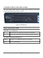
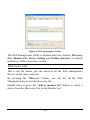
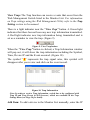
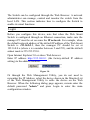
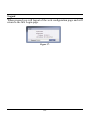
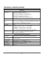
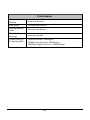
FCC Warning This equipment has been tested and found to comply with the regulations for a Class A digital device, pursuant to Part 15 of the FCC Rules. These limits are designed to provide reasonable protection against harmful interference when the equipment is operated in a commercial environment. This equipment generates, uses, and can radiate radio frequency energy and, if not installed and used in accordance with this user’s guide, may cause harmful interference to radio communications. Operation of this equipment in a residential area is likely to cause harmful interference, in which case the user will be required to correct the interference at his or her own expense. CE Mark Warning This is a Class A product. In a domestic environment, this product may cause radio interference, in which case the user may be required to take adequate measures. VCCI Warning This is a product of VCCI Class A Compliance. UL Warning a) Elevated Operating Ambient Temperature- If installed in a closed or multi-unit rack assembly, the operating ambient temperature of the rack environment may be greater than room ambient. Therefore, consideration should be given to installing the equipment in an environment compatible with the manufacturer's maximum rated ambient temperature (Tmra). b) Reduced Air Flow- Installation of the equipment in a rack should be such that the amount of air flow required for safe operation of the equipment is not compromised. c) Mechanical Loading- mounting of the equipment in the rack should be such that a hazardous condition is not achieved due to uneven mechanical loading. d) Circuit Overloading- Consideration should be given to the connection of the equipment to the supply circuit and the effect that overloading of circuits might have on over current protection and supply wiring. Appropriate consideration of equipment nameplate ratings should be used when addressing this concern. e) Reliable Earthing - Reliable earthing of rack-mounted equipment should be maintained. Particular attention should be given to supply connections other than direct connections to the branch circuit (e.g., use of power strips). Ver. C1-1.00 TABLE OF CONTENT About This Guide................................................................................. 1 Purpose ............................................................................................ 1 Terms/Usage .................................................................................... 1 Introduction .......................................................................................... 3 Gigabit Ethernet Technology ........................................................... 3 Fast Ethernet Technology ................................................................ 4 Switching Technology ..................................................................... 5 VLAN (Virtual Local Area Network) .............................................. 6 Features ............................................................................................ 6 Unpacking and Installation .................................................................. 9 Unpacking ........................................................................................ 9 Installation ....................................................................................... 9 Rack Mounting .............................................................................. 10 Connecting Network Cable ............................................................ 11 AC Power....................................................................................... 12 Identifying External Components ...................................................... 13 Front Panel ..................................................................................... 13 Rear Panel ...................................................................................... 14 Understanding LED Indicators .......................................................... 15 Power and System LEDs ............................................................... 15 1000BASE-T Port 1~24 Status LEDs ............................................ 16 Mini-GBIC Port 23 ~ 24 Status LEDs ........................................... 17 Configuration ..................................................................................... 19 i Installing the Web Management Utility ......................................... 19 Discovery List ................................................................................ 20 Monitor List ................................................................................... 21 Device Setting ................................................................................ 23 Toolbar ........................................................................................... 25 Configuring the Switch .................................................................. 25 Login .............................................................................................. 26 Setup Setting .................................................................................. 27 Port Settings ............................................................................... 28 IEEE 802.1Q VLAN .................................................................. 29 Trunk Setting ............................................................................. 39 Mirror Setting............................................................................. 40 IEEE 802.1p Default Priority ..................................................... 41 Broadcast Storm Control Setting ............................................... 42 Jumbo Frame Setting ................................................................. 42 Advanced Setting ........................................................................... 43 SNMP Setting ............................................................................ 43 Spanning Tree Setting ................................................................ 45 802.1x Setting ............................................................................ 47 IGMP Snooping Setting ............................................................. 49 IGMP VLAN Setting ................................................................. 51 System Setting ............................................................................... 53 System Information .................................................................... 53 System Setting ........................................................................... 54 Trap Setting................................................................................ 56 ii Password Setting ........................................................................ 57 Statistic....................................................................................... 58 Factory Reset ............................................................................. 60 Backup Setting ........................................................................... 60 Firmware Upload ....................................................................... 61 System Reboot ........................................................................... 61 Logout ........................................................................................ 62 Technical Specifications ................................................................. 63 iii ABOUT THIS GUIDE Congratulations on your purchase of the TEG-240WS 24-Port Gigabit Web Smart Switch w/ 2 Shared Mini-GBIC Slots. This device integrates 1000Mbps Gigabit Ethernet, 100Mbps Fast Ethernet and 10Mbps Ethernet network capabilities in a highly flexible package. Purpose This guide discusses how to install your TEG-240WS 24-Port Gigabit Web Smart Switch w/ 2 Shared Mini-GBIC Slots. Terms/Usage In this guide, the term “Switch” (first letter upper case) refers to your TEG-240WS 24-Port Gigabit Web Smart Switch w/ 2 Shared MiniGBIC Slots and “switch” (first letter lower case) refers to other Ethernet switches. 1 INTRODUCTION This chapter describes the features of the TEG-240WS 24-Port Gigabit Web Smart Switch w/ 2 Shared Mini-GBIC Slots and some background information about Ethernet/Fast Ethernet/Gigabit Ethernet switching technology. Gigabit Ethernet Technology Gigabit Ethernet is an extension of IEEE 802.3 Ethernet utilizing the same packet structure, format, and support for CSMA/CD protocol, full duplex, flow control, and management objects, but with a tenfold increase in theoretical throughput over 100-Mbps Fast Ethernet and a hundredfold increase over 10-Mbps Ethernet. Since it is compatible with all 10-Mbps and 100-Mbps Ethernet environments, Gigabit Ethernet provides a straightforward upgrade without wasting a company’s existing investment in hardware, software, and trained personnel. The increased speed and extra bandwidth offered by Gigabit Ethernet is essential to coping with the network bottlenecks that frequently develop as computers and their busses get faster and more users use applications that generate more traffic. Upgrading key components, such as your backbone and servers to Gigabit Ethernet can greatly improve network response times as well as significantly speed up the traffic between your subnets. Gigabit Ethernet enables fast optical fiber connections to support video conferencing, complex imaging, and similar data-intensive applications. Likewise, since data transfers occur 10 times faster than Fast Ethernet, servers outfitted with Gigabit Ethernet NIC’s are able to perform 10 times the number of operations in the same amount of time. 3 In addition, the phenomenal bandwidth delivered by Gigabit Ethernet is the most cost-effective method to take advantage of today and tomorrow’s rapidly improving switching and routing internetworking technologies. And with expected advances in the coming years in silicon technology and digital signal processing that will enable Gigabit Ethernet to eventually operate over unshielded twisted-pair (UTP) cabling, outfitting your network with a powerful 1000-Mbpscapable backbone/server connection creates a flexible foundation for the next generation of network technology products. Fast Ethernet Technology The growing importance of LANs and the increasing complexity of desktop computing applications are fueling the need for high performance networks. A number of high-speed LAN technologies have been proposed to provide greater bandwidth and improve client/server response times. Among them, 100BASE-T (Fast Ethernet) provides a non-disruptive, smooth evolution from the current 10BASE-T technology. The non-disruptive and smooth evolution nature, and the dominating potential market base, virtually guarantees cost-effective and high performance Fast Ethernet solutions. 100Mbps Fast Ethernet is a standard specified by the IEEE 802.3 LAN committee. It is an extension of the 10Mbps Ethernet standard with the ability to transmit and receive data at 100Mbps, while maintaining the CSMA/CD Ethernet protocol. Since the 100Mbps Fast Ethernet is compatible with all other 10Mbps Ethernet environments, it provides a straightforward upgrade and takes advantage of the existing investment in hardware, software, and personnel training. 4 Switching Technology Another approach to pushing beyond the limits of Ethernet technology is the development of switching technology. A switch bridges Ethernet packets at the MAC address level of the Ethernet protocol transmitting among connected Ethernet or Fast Ethernet LAN segments. Switching is a cost-effective way of increasing the total network capacity available to users on a local area network. A switch increases capacity and decreases network loading by dividing a local area network into different segments, which don’t compete with each other for network transmission capacity. The switch acts as a high-speed selective bridge between the individual segments. The switch, without interfering with any other segments, automatically forwards traffic that needs to go from one segment to another. By doing this the total network capacity is multiplied, while still maintaining the same network cabling and adapter cards. Switching LAN technology is a marked improvement over the previous generation of network bridges, which were characterized by higher latencies. Routers have also been used to segment local area networks, but the cost of a router, the setup and maintenance required make routers relatively impractical. Today switches are an ideal solution to most kinds of local area network congestion problems. 5 VLAN (Virtual Local Area Network) A VLAN is a group of end-stations that are not constrained by their physical location and can communicate as if a common broadcast domain, a LAN. The primary utility of using VLAN is to reduce latency and need for routers, using faster switching instead. Other VLAN utility includes: Security, Security is increased with the reduction of opportunity in eavesdropping on a broadcast network because data will be switched to only those confidential users within the VLAN. Cost Reduction, VLANs can be used to create multiple broadcast domains, thus eliminating the need of expensive routers. Features 24 x 1000BASE-T Auto-negotiation Gigabit Ethernet ports 2 x Combo mini-GBIC (Auto-Sense) for optional mini-GBIC transceiver to extend distance, share with 2 1000BASE-T ports All 1000BASE-T ports support auto MDI/MDIX, so there is no need to use cross-over cables or an up-link port Half duplex transfer mode for connection speed 10Mbps and 100Mbps Full duplex transfer mode for connection speed of 10Mbps, 100Mbps and 1000Mbps Store-and-Forward switching scheme capability to support rate adaptation and ensure data integrity Up to 8K unicast addresses entities per device, self-learning, and table aging 512 KBytes packet buffer 6 Supports IEEE 802.3x flow control for full-duplex mode ports Supports IEEE 802.1Q VLAN Supports IEEE 802.1p Priority Queues Supports Static Port Trunk Supports IGMP Snooping Supports SNMP for RFC1213 MIB II and Private MIB Supports IEEE 802.1D Spanning Tree Supports 802.1x port based access control Supports Jumbo Frame Supports Broadcast Storm Control Supports Port Mirroring Supports Port Setting for Speed, Flow control Easy configuration via WEB Browser Easy setting via Web Management Utility Standard 19” Rack-mount size 7 UNPACKING AND INSTALLATION This chapter provides unpacking and installation information for the Switch. Unpacking Open the shipping cartons of the Switch and carefully unpacks its contents. The carton should contain the following items: TEG-240WS 24-Port Gigabit Web Smart Switch w/ 2 Shared Mini-GBIC Slots Multi-Language Quick Installation Guide CD-COM (Utility & User’s Guide) Power Cord Rack Mount Kit (Rubber Feet, Screws and Mounting Brackets) If any item is found missing or damaged, please contact your local reseller for replacement Installation The site where you install the hub stack may greatly affect its performance. When installing, consider the following pointers: Install the Switch in a fairly cool and dry place. See Technical Specifications for the acceptable temperature and humidity operating ranges. Install the Switch in a site free from strong electromagnetic field generators (such as motors), vibration, dust, and direct exposure to sunlight. Leave at least 10cm of space at the front and rear of the hub for ventilation. 9 Install the Switch on a sturdy, level surface that can support its weight, or in an EIA standard-size equipment rack. For information on rack installation, see the next section, Rack Mounting. When installing the Switch on a level surface, attach the rubber feet to the bottom of each device. The rubber feet cushion the hub and protect the hub case from scratching. Figure 1. Attach the adhesive rubber pads to the bottom Rack Mounting The switch can be mounted in an EIA standard-size, 19-inch rack, which can be placed in a wiring closet with other equipment. Attach the mounting brackets at the switch’s front panel (one on each side), and secure them with the provided screws. Figure 2. Combine the Switch with the provided screws 10 Then, use screws provided with the equipment rack to mount each switch in the rack. Figure 3. Mount the Switch in the rack Connecting Network Cable The Switch supports 1000Mbps Gigabit Ethernet that runs in Autonegotiation mode and 10Mbps Ethernet or 100Mbps Fast Ethernet that runs both in half and full duplex mode and 1000Mbps Gigabit Ethernet runs in full duplex mode using four pairs of Category 5 cable. These 1000BASE-T ports are Auto-MDI type port. The Switch can auto transform to MDI-II or MDI-X type, so you can just make an easy connection that without worrying if you are using a standard or crossover twisted-pair cable. There are additional 2 ports combo mini-GBIC slot for optional miniGBIC module. 11 AC Power The Switch used the AC power supply 100-240V AC, 50-60 Hz. The power switch is located at the rear of the unit adjacent to the AC power connector and the system fan. The switch’s power supply will adjust to the local power source automatically and may be turned on without having any or all LAN segment cables connected. 12 IDENTIFYING EXTERNAL COMPONENTS This chapter describes the front panel, rear panel, and LED indicators of the Switch. Front Panel The figure below shows the front panels of the Switch. Figure 4. Front panel LED Indicators: Comprehensive LED indicators display the status of the switch and the network (see the LED Indicators chapter below). 1000BASE-T Gigabit Ethernet Ports (Port 1~24): The Switch twenty-four Gigabit twisted pair ports, supported auto negotiable 10/100/1000Mbps and auto MDI/MDIX crossover detection function, this function gives true “plug and play” capability, just need to plug-in the network cable to the hub directly and don’t care if the end node is NIC (Network Interface Card) or switch and hub. These ports can operate in half-duplex mode 10/100/1000Mbps. for 10/100Mbps and full- duplex mode for Note: When the port is set to “Forced Mode”, the Auto MDI/MDIX will be disabled. 13 Mini-GBIC Slots (Port 23~24) The Switch is equipped with two combo mini-GBIC ports, supported optional 1000BASE-SX/LX mini-GBIC module. The 1000BASE-T port 23 and 24 are the same ports with the miniGBIC port 23 and 24, when plug in the mini-GBIC module, the device will activate mini-GBIC, and the RJ45 port will be disabled. Rear Panel The rear panel of the Switch consists of an AC power connector and Reset button. The following shows the rear panel of the Switch. Figure 5. Rear panel AC Power Connector: This is a three-pronged connector that supports the power cord. Plug in the female connector of the provided power cord into this connector, and the male into a power outlet. Supported input voltages range from 100-240V AC at 50-60Hz. Reset: The Reset button is to reset all the setting back to the factory default. Note: Be sure that you recorded the setting of your device, else all the setting will be erased when pressing the “Reset” button. 14 UNDERSTANDING LED INDICATORS The front panel LEDs provides instant status feedback, and, helps monitor and troubleshoot when needed. Figure 6. LED indicators Power and System LEDs POWER: Power Indicator On : When the Power LED lights on, the Switch is receiving power. Off : When the Power turns off or the power cord has improper connection. SYSTEM: Management Indicator Blinking : When the CPU is working, the System LED is blinking. On/Off : The CPU is not working. 15 1000BASE-T Port 1~24 Status LEDs Link/ACT: Link/Activity On : When the Link/ACT LED lights on, the respective port is successfully connected to an Ethernet network. Blinking : When the Link/ACT LED is blinking, the port is transmitting or receiving data on the Ethernet network. Off : No link. Green : When the Speed LED lights green, the respective port is connected to a 1000Mbps Gigabit Ethernet network. Amber : When the Speed LED lights amber, the respective port is connected to a 100Mbps Fast Ethernet network. Speed Off When the Speed LED lights off, the respective port is connected to a 10Mbps Ethernet network. 16 Mini-GBIC Port 23 ~ 24 Status LEDs Link/ACT On : When the fiber line connected to the mini-GBIC module is installed and connected to a network, the Link/ACT LED will lights on. Blinking : When the Link/ACT LED is blinking, the port is transmitting or receiving data on the Gigabit Ethernet network. Off : Fiber line or mini-GBIC module is not installed. Green : When the Speed LED lights green, the respective port is connected to a 1000Mbps Gigabit Ethernet network. Amber : When the Speed LED lights amber, the respective port is connected to a 100Mbps Fast Ethernet network. Speed Off When the Speed LED lights off, the respective port is connected to a 10Mbps Ethernet network. 17 CONFIGURATION Through the Web Browser you can configure the Switch such as VLAN, Port Trunking, Jumbo Frame… etc. With the attached Web Management Utility, you can easily discover all the Web Management Switch, assign the IP Address, changing the password and upgrading the new firmware. Installing the Web Management Utility The following are step-by-step instructions for installing the Web Management utility. 1. 2. Insert the Utility CD in the CD-ROM Drive. Click Install Utility icon to start 3. 4. Follow the on-screen instructions to install the utility. Upon completion, go to Program Files Æ TRENDnetÆ Web Smart Switch Management Utility and open the Web Management utility. Figure 7 19 Figure 8. Web Management Utility The Web Management Utility is divided into four sections, Discovery List, Monitor List, Device Setting and Toolbar function, for details instruction, follow the below section. Discovery List This is the list where you can discover all the Web management devices in the entire network. By pressing the “Discover” button, you can list all the Web Management devices in the discovery list. Double click or press the “Add to monitor list” button to select a device from the Discovery List to the Monitor List. 20 System word definitions in the Discovery List: z z z z z z z z z z MAC Address: Shows the device MAC Address. IP Address: Shows the current IP address of the device. Protocol version: Shows the version of the Utility protocol. Product Name: Shows the device product name. System Name: Shows the appointed device system name. DHCP: Shows the DHCP status of the device. Location: Shows where the device is located. Trap IP: Shows the IP where the Trap to be sent. Subnet Mask: Shows the Subnet Mask set of the device. Gateway: Shows the Gateway set of the device. Monitor List All the Web Smart Device in the Monitor List can be monitored; you can also receive the trap and show the status of the device. System word definitions in the Monitor List: z z z z z z z z z z z S: Shows the system symbol of the Web-Smart device, represent for device system is not alive. IP Address: Shows the current IP address of the device. MAC Address: Shows the device MAC Address. Protocol version: Shows the version of the Utility protocol. Product Name: Shows the device product name. System Name: Shows the appointed device system name. DHCP: Shows the DHCP status of the device. Location: Shows where the device is located. Trap IP: Shows the IP where the Trap to be sent. Subnet Mask: Shows the Subnet Mask set of the device. Gateway: Shows the Gateway set of the device. 21 View Trap: The Trap function can receive events that occur from the Web Management Switch listed in the Monitor List. For information on Trap settings using the Web Management Utility refer to the Trap Setting section in the manual. There is a light indicator near the “View Trap” button. A Green light indicates that there has not been any new trap information transmitted. A Red light indicates new trap information being transmitted and is set as a reminder to view the trap. (Figure 9) Figure 9. View Trap button When the “View Trap” button is clicked, a Trap Information window will pop out, it will show the trap information including the Symbol, Time, Device IP and the Event occurred. (Figure 10) The symbol “ ” represents the trap signal arise, this symbol will disappear after you review and click on the event record. Figure 10. Trap Information Note: In order to receive Trap information, switch has to be configured with Trap IP and Trap Events in Web browser, which are available in the Trap Setting Menu (see Page 56 for detail). Add Item: To add a device to the Monitor List manually, enter the IP 22 Address of the device that you want to monitor. Delete Item: To delete the selected device in the Monitor List. Device Setting You can set the device by using the function key in the Device Setting Dialog box. Configuration Setting: In this Configuration Setting, you can set the IP Address, Subnet Mask, Gateway, Set Trap to (Trap IP Address), System name, Location and DHCP function. Select the device in the Discovery list or Monitor List and press this button, then the Configuration Setting window will pop out as Figure 10, after filling up the data that you want to change, you must fill up the password and press the “Set” to process the data changed immediately. The default password of this TEG-240WS 24-Port 10/100/1000Mbps Gigabit Ethernet Web Smart Switch configuration is “admin”. Figure 11. Configuration Setting Password Change: You can use this Password Change when you need to change the password, fill in the password needed in the dialog box and press “Set” button to proceed the password change immediately. 23 Figure 12. Password Change Firmware Upgrade: When the device has a new function, there will be a new firmware to update the device, use this function to update. Select the path of where the firmware updated firmware is located by clicking “Browse”. Once you have selected the firmware, type the password of the device and click the “Start” button to proceed. Figure 13. Firmware Upgrade Access Web: Double click the device in the Monitor List or select a device in the Monitor List and press this “Web Access” button to access the device in Web browser. DHCP Refresh: Press this “DHCP Refresh” button to refresh IP address of selected device form DHCP server. 24 Toolbar The toolbar in the Web Management Utility have four main tabs, File, View, Options and Help. In the “File TAB”, there are Monitor Save, Monitor Save As, Monitor Load and Exit. z Monitor Save: To record the setting of the Monitor List to the default, when you open the Web Management Utility next time, it will auto load the default recorded setting. z Monitor Save As: To record the setting of the Monitor List in appointed filename and file path. z Monitor Load: To manually load the setting file of the Monitor List. z Exit: To exit the Web Management Utility. In the “View TAB”, there are view log and clear log function, this function will help you to show trap setting. z View Log: To show the event of the Web Management Utility and the device. z Clear Log: to clear the log. In the “Option TAB”, there are Refresh Time function, this function helps you to refresh the time of monitoring the device. Choose 15 secs, 30 secs, 1 min, 2 min and 5 min to select the time of monitoring. In the “Help TAB”, there is About function, it will show out the version of the Web Management Utility. Configuring the Switch The TEG-240WS 24-Port 10/100/1000Mbps Gigabit Ethernet Web Smart Switch has a Web GUI interface for smart switch configuration. 25 The Switch can be configured through the Web Browser. A network administrator can manage, control and monitor the switch from the local LAN. This section indicates how to configure the Switch to enable its smart functions Login Before you configure this device, note that when the Web Smart Switch is configured through an Ethernet connection, make sure the manager PC must be set on same the IP network. For example, when the default network address of the default IP address of the Web Smart Switch is 192.168.0.1, then the manager PC should be set at 192.168.0.x (where x is a number between 2 and 253), and the default subnet mask is 255.255.255.0. Open Internet Explorer 5.0 or above Web browser. Enter IP address http://192.168.0.1 (the factory-default IP address setting) to the address location. Figure 14. Or through the Web Management Utility, you do not need to remember the IP Address, select the device shown in the Monitor List of the Web Management Utility to settle the device on the Web Browser. When the following dialog page appears, remain enter the default password "admin" and press Login to enter the main configuration window. 26 Figure 15. After entering the password, the main page comes up, the screen will display the device status. Figure 16. System Information Setup Setting Find that there are seven items, including Port Setting, IEEE 802.1Q VLAN Settings, Trunk Setting, Mirror Setting, IEEE 802.1p Default Priority, Broadcast Strom Control Setting, Jumbo Frame Setting in 27 Setup menu. Port Settings In Port Settings menu (Figure 17), this page will show each port’s status, selected drop down menu to set each port’s Speed, and QoS priority then press “Apply” button to activate changes. To refresh the information table to view the latest port setting and Link Status, press the Refresh button. The Link Status in the screen will show the connection speed and duplex mode; else this dialog box will show Down when the port is disconnected. Figure 17. Port Setting Note: The priority of Gigabit Fiber port is higher than Copper. Speed: The 1000BASE-T connections can operate in Forced Mode settings (1000M Full, 100M Full, 100M Half, 10M Full, 10M Half), Auto, or Disable. The default setting for all ports are Auto. The mini-GBIC (Gigabit Fiber) connections can operate in Forced Mode settings (1000M Full), Auto, or Disable 28 Flow Control: This setting determines whether or not the Switch will be handling flow control. Set Flow Control to Enable for avoiding data transfer overflow. Or it sets to Disable; there is either no flow control or other hardware/software management. When the port is set to forced mode, then the flow control will automatically set to Disable. QoS: Displays each port’s 802.1p QoS priority level for received data packet handling. Default setting for all ports is Middle. You can change the priority settings in 802.1p Default Priority. IEEE 802.1Q VLAN A VLAN is a group of ports that can be anywhere in the network, but communicate as though they were in the same area. VLANs can be easily organized to reflect department groups (such as R&D, Marketing), usage groups (such as e-mail), or multicast groups (multimedia applications such as video conferencing), and therefore help to simplify network management by allowing users to move devices to a new VLAN without having to change any physical connections. The IEEE 802.1Q VLAN Configuration page provides powerful VID management functions. The original settings have the VID as 01, named “default”, and all 24 ports as “Untagged”. Asymmetric VLAN IEEE 802.1Q Asymmetric VLAN default setting is “Disabled”, you can press “Enabled” radio button and Apply it to submit the 29 Asymmetric VLAN function. Figure 18. Enabled Asymmetric VLAN function Figure 19. Change setting warning message Note: The Settings of VLAN, IGMP Snooping and Forwarding Table will be reset to default. Untag Asymmetric VLAN Setting: The IEEE 802.1Q VLAN Configuration page provides powerful VID management functions. The original default VLAN setting has the VID as 01, named “default”, and contains all ports as “Untagged”. 30 Figure 20. 802.1Q Asymmetric VLAN Setting Add VID: Click to create a new VID group, assigning ports 1 ~ 24 as Untag, Tag, or Not Member. A port can be “Untagged” in only one VID. To save the VID group, press Apply. Figure 21. Add New VID VID: A unique VLAN ID. VLAN Name: A VLAN name is used to associate with the VLAN ID. Port: The switch port number. Untag: Outgoing frames without VLAN tag. Tag: Outgoing frames with VLAN tag. Not Member: The port number which not to be grouped. Select All: Select all ports to be VLAN members or not VLAN members. Cancel: To call the modifications off. 31 Apply: To activate and save the modifications. Delete: Click to delete selected VID. Figure 22. Delete VID To change exist IEEE 802.1Q VLAN setting, press the VID to modify that IEEE 802.1Q VLAN setting. Figure 23. Modify VID PVID settings: While receiving an untagged frame from the port, the switch will assign a tag to the frame, using the PVID of the port as its VID. Figure 24. PVID Setting 32 Example 1: Here is an example of two VLAN groups with several ports in each group and VLAN 1 (VID 01) does not have communication with VLAN 2 (VID 02). Figure 25. Step1: Set VLAN1 port 9~24 to “Not Member”, then apply setting. Figure 26. Step2: Create VID 02 and set port 9~24 to “Untag Port” member, then apply setting. Figure 27. 33 Example2: 802.1Q Asymmetric VLAN settings example: Port 1~16 in VLAN 1, port1~5 in VLAN 2, port1,6~9 in VLAN 3. All VLAN1~3 have access to Internet via port 1. Figure 28. Note: The multi-need server must be support IEEE 802.1Q VLAN Step1: Enable Asymmetric VLAN function. Figure 29. Step2: Set VLAN1 port 1~24 to “Untag” ports, then apply setting. Figure 30. 34 Step3: Create VID 02 and set port 1~5 to “Untag” ports and port 6~24 to “Not Member” ports, then apply setting. Figure 31. Step4: Create VID03 and set port 1 and 6~9 to “Untag” ports, then apply setting. Figure 32. Step5: Set PVID Port 3~9 PVID value to below list: Figure 33. 35 Note: 1. Untag port VLAN member can exist in different VLAN groups simultaneously when Asymmetric VLAN function enabled. 2. You must create VLAN and add VLAN member first that just can set PVID setting. 3. You must change Untag Port PVID to another existent VLAN ID that just can remove Untag port member from VLAN group Tag VLAN Setting The IEEE802.1Q protocol defines a new format of the frame; it adds a tag header in the original Ethernet frame, as follows: IEEE802.1Q Tag VLAN is divided by VLAN ID (VID). On receiving a frame, the switch checks the VID in the tag header of the frame to decide which VLAN it belongs to. If the receiving frame doesn’t contain the tag header, the switch will assign a tag to the frame, using the PVID of the port as its VID. Figure 34. 36 Example 3: Create two VLAN groups for Tag ports multi-need server application setting and two VLAN clients cannot negotiate to each other. (Asymmetric VLAN function disabled) Step1: Set VLAN1 port 1 to “Tag” and port 9~24 to “Not Member”, then apply setting. Figure 35. Step 2: Create VID 02 and set port 1 to “Tag” port and port 9~24 to “Untag” ports, then apply setting. Figure 36. Note: The multi-need server must be support IEEE 802.1Q VLAN, the sever uplink port is port1. 37 Example 4: Setting Tag VLAN on two switches. Switch 1’s VLAN 1 (2 ~ 3 ports) have access to the Switch 2’s VLAN 1 (2 ~ 3 ports). The settings of VLAN group for two devices are same. Step1: Set Switch1’s VLAN1 port 1and 4~24 to “Not Member”, then apply setting. Figure 37. Step2: Set Switch2’s VLAN1 member as Switch1. Step3: Uplink two switches via Port 24. 38 Trunk Setting The Trunking function enables the cascading of two or more ports for a combined larger bandwidth. Up to six Trunk groups may be created, each supporting up to 8 ports. Add a Trunking Name and select the ports to be trunked together, and click Apply to activate the selected Trunking groups. Figure 38. Trunk Configuration Be sure that the selected trunk setting port must connect to the device with a same VLAN group. 39 Mirror Setting Port Mirroring is a method of monitoring network traffic that forwards a copy of each incoming and/or outgoing packet from one port of the Switch to another port where the packet can be studied. This enables network managers to better monitor network performances. Figure 39. Mirror Setting Selection of the Sniffer mode is as follow: TX (transmit) mode: this mode will duplicate the data transmit from the source port and forward to the Sniffer port. RX (receive) mode: this mode will duplicate the data that send to the source and forward to the Sniffer port. Both (transmit and receive) mode: this mode will duplicate both the data transmit from and data that send to the source port, then it will forward to the Sniffer port. 40 IEEE 802.1p Default Priority This feature displays the status Quality of Service priority levels of each port, and for packets that are untagged, the switch will assign the priority in the tag depending on your configuration. Figure 40 IEEE 802.1p Default Priority Setting 41 Broadcast Storm Control Setting The Broadcast Storm Control feature provides the ability to control the receive rate of broadcasted packets. If Enabled (default is Disabled), threshold settings of 8,000 ~ 4,096,000 bytes per second can be assigned. Press Apply for the settings to take effect. Figure 18. Broadcast Storm Control Setting Jumbo Frame Setting Jumbo Frames enable the transportation of identical data in fewer frames. This ensures less overhead, lower processing time, and fewer interruptions. Maximum packet length supported is 10240 bytes. Figure 19. Jumbo Frame Setting 42 Advanced Setting Find that there are four items, including SNMP Setting, Spanning Tree Setting, 802.3x Setting and IGMP Snooping Setting in Advanced menu. SNMP Setting The Web Smart Switch supports SNMP include software (referred to as an agent), which runs locally on the device. A defined set of variables (managed objects) is maintained by the SNMP agent and used to manage the device. These objects are defined in a Management Information Base (MIB), which provides a standard presentation of the information controlled by the on-board SNMP agent. SNMP defines both the format of the MIB specifications and the protocol used to access this information over the network. Figure 20. SNMP Setting 43 SNMP Setting: Enable or Disable the SNMP function on the Web Smart Switch. Community Setting: In support of SNMP version 1, the Web-Smart Switch accomplishes user authentication by using Community Settings that function as passwords. The remote user SNMP application and the Switch SNMP must use the same community string. SNMP packets from a station that are not authenticated are ignored (dropped). Read_Only: The community with read-only privilege allows authorized management stations to retrieve MIB objects. (Default: public) Read_Write: The community with read/write privilege allows authorized management stations to retrieve and modify MIB objects. (Default setting: private) Trap Setting: Enable or Disable the Trap function on the Web Smart Switch. Traps are messages that alert network personnel of events that occur on the Switch. Such events can be as serious as a reboot (someone accidentally turned the Switch OFF), or less serious events such as a port status change. The Switch can generate traps and send them to the trap recipient (i.e. network administrator). Trap Name: Enter a Trap Name (i.e. Trap Name must be selected from a Community Name) IP: Enter the IP of the device to be monitored, and choose the event(s) to trap. Event: The available trap Events to choose from include: System Device Bootup, Fiber Link Up / Link Down, Fiber Abnormal Receive Error, Fiber Abnormal Transmit Error, Twisted Pair Link Up / Link Down, Twisted Pair Abnormal Receive Error, Twisted Pair Abnormal Transmit Error. 44 Spanning Tree Setting The Web Smart Switch supports IEEE 802.1D Spanning Tree Protocol (STP) implementation is designed to prevent network loops that could cause a broadcast storm. When the physical links forming a loop provide redundancy, only a single path will be forwarding frames. If the link fails, STP activates a redundant link automatically. Figure 21. Spanning Tree Setting 802.11D Spanning Tree: Enable or Disable the 802.11D Spanning function on the Web Smart Switch. Bridge Priority: This value between 0 and 65535 specifies the priority for forwarding packets: the lower the value, the higher the priority. The default is 32768. 45 Bridge Max Age: This value may be set to ensure that old information does not endlessly circulate through redundant paths in the network, preventing the effective propagation of the new information. Set by the Root Bridge, this value will aid in determining that the Switch has spanning tree configuration values consistent with other devices on the bridged LAN. If the value ages out and a BPDU has still not been received from the Root Bridge, the Switch will start sending its own BPDU to all other switches for permission to become the Root Bridge. If it turns out that the Switch has the lowest Bridge Identifier, it will become the Root Bridge. A time interval may be chosen between 6 and 40 seconds. The default value is 20. Bridge Hello Time: The user may set the time interval between transmissions of configuration messages by the root device, thus stating that the Switch is still functioning. The default is 2 seconds. Bridge Forward Delay: This sets the maximum amount of time that the root device will wait before changing states. The default is 15 seconds. Root Bridge: Displays the MAC address of the Root Bridge. Root port: Displays the root port. Root Path Cost: Shows the root path cost. Path Cost: This defines a metric that indicates the relative cost of forwarding packets to specified port list. The lower the number, the greater the probability the port will be chosen to forward packets. The default value is 19. Path Priority: Select a value between 0 and 255 to specify the priority for a specified port for forwarding packets: the lower the value, the higher the priority. The default is 128. 46 802.1x Setting The IEEE 802.1x provides a security standard for network access control. 802.1x holds a network port disconnected until authentication is completed. Depending on the results, the port is either made available to the user, or the user is denied access to the network. 802.1X uses the Extensible Authentication Protocol (EAP) for passing authentication messages. Figure 22. 802.1x Setting Enable: Enable or Disable the 802.11x function on the Web Smart Switch. Radius Server IP: Enter the IP address of the Radius Server. 47 Authentication Port: Sets primary port for security monitoring. Default is 1812. Key/Confirm Key: Masked password matching the Radius Server Key. TxPeriod: Sets the number of seconds that the switch waits for a response to an EAP-request/identity frame from the client before retransmitting the request. Default is 24 seconds. ReAuthEnabled: This Enable or Disable the periodic ReAuthentication control. When the 802.1X function is Enabled, the ReAuthEnabled function is by default also Enabled. QuietPeriod: Sets the number of seconds that the switch remains in the quiet state following a failed authentication exchange with the client. Default 80 seconds. SuppTimeout: Sets the switch-to-client retransmission time for the EAP-request frame. Default is 12 seconds. ServerTimeout: Sets the amount of time the switch waits for a response from the client before resending the response to the authentication server. Default is 16 seconds. MaxReq: This parameter specifies the maximum number of times that the switch retransmits an EAP Request packet to the client before it times out the authentication session. Default is 5 times. ReAuthPeriod: This command affects the behavior of the switch only if periodic re-authentication is enabled. Default is 3600. 802.1x Port Access Control: Enable or disable the 802.1x port access on selected port. 48 IGMP Snooping Setting With Internet Group Management Protocol (IGMP) snooping, the Web-Smart Switch can make intelligent multicast forwarding decisions by examining the contents of each frame’s Layer 2 MAC header. IGMP snooping can help reduce cluttered traffic on the LAN. With IGMP snooping enabled globally, the Web-Smart Switch will forward IP multicast traffic only to connections that have group members attached. Figure 23. IGMP Global Setting IGMP Snooping: Enable or Disable the IGMP Snooping function on the Web Smart Switch. Querier State: Enable or Disable the Querier State of IGMP Snooping. 49 Query Interval (60-600 sec): The Query Interval is the interval between General Queries sent. By adjusting the Query Interval, the number of IGMP messages can increase or decrease; larger values cause IGMP Queries to be sent less often. Default is 125 seconds. Max Response Time (10-25 sec): The Max Response Time specifies the maximum allowed time before sending a responding report. Adjusting this setting effects the "leave latency", or the time between the moment the last host leaves a group and when the routing protocol is notified that there are no more members. It also allows adjustments for controlling the frequency of IGMP traffic on a subnet. Default is 10 seconds. Robustness Variable (1-255): The Robustness Variable allows adjustment for the expected packet loss on a subnet. If a subnet is expected to be lousy, the Robustness Variable may be increased. The Robustness Variable cannot be set zero, and SHOULD NOT be one. Default is 2 times. Last Member Query Interval (1-25 sec): The Last Member Query Interval is the Max Response Time inserted into Group-Specific Queries sent in response to Leave Group messages, and is also the amount of time between Group-Specific Query messages. This value may be adjusted to modify the "leave latency" of the network. A reduced value results in reduced time to detect the loss of the last member of a group. Default is 1 second. Host Timeout (130-1225 sec): This is the interval after which a learnt host port entry will be purged. For each host port learnt, a 'PortPurgeTimer' runs for 'HostPortPurgeInterval'. This timer will be restarted whenever a report message from host is received over that port. If no report messages are received for 'HostPortPurgeInterval' time, the learnt host entry will be purged from the multicast group. Default is 260 seconds. 50 Router Timeout (60-600 sec): This is the interval after which a learnt router port entry will be purged. For each router port learnt, a 'RouterPortPurgeTimer' runs for 'RouterPortPurgeInterval'. This timer will be restarted whenever a router control message is received over that port. If no router control messages are received for 'RouterPortPurgeInterval' time, the learnt router port entry will be purged. Default is 125 seconds. Leave Timer (0-25 sec): This is the interval after which a Leave message is forwarded on a port. When a leave message from a host for a group is received, a group-specific query is sent to the port on which the leave message is received. A timer is started with a time interval equal to IgsLeaveProcessInterval. If a report message is received before above timer expires, the Leave message is dropped. Otherwise the Leave message is either forwarded to the port. Default is 1 second. IGMP VLAN Setting To enable IGMP snooping for a given VLAN, select Enable under State then press the Edit button under Static Router Port Setting, then select the ports to be assigned for IGMP snooping for the VLAN, and press Apply for changes to take effect. Figure 24. VLAN Setting of IGMP Snooping 51 Figure 25. IGMP-Router Port Setting To view the Multicast Entry Table for a given VLAN, press the View button. Figure 26. IGMP – Multicast Entry Table Setting 52 System Setting Find that there are nine items, including System Information, System Setting, Trap Setting, Password Setting, Statistics, Factory Reset, Backup Setting, Firmware Upload and System Reboot in System menu. System Information Press on “System Information” to display the system information status on this screen, it will show the Product Name, Firmware Version, Protocol Version, MAC Address, System Name, Location Name, IP Address, Subnet Mask, Default Gateway, Trap IP, Login Timeout and System Up Time. Figure 27. System Information 53 System Setting The System Setting includes IP Information and System information. There are two ways for the switch to attain IP: Static and DHCP (Dynamic Host Configuration Protocol). When using static mode, the IP Address, Subnet Mask and Gateway can be manually configured. When using DHCP mode, the Switch will first look for a DHCP server to provide it with an IP address, network mask, and default gateway before using the default or previously entered settings. By default the IP setting is static mode with 192.168.0.1 as the IP address. By entering a System Name and System Location, the device can easily be recognized through the Web Management Utility and in other Web-Smart devices on the LAN. The Login Timeout controls the idle time-out for security purposes, when there is no action in the Web-based Utility. When the Login Timeout expires, the Web based Utility requires a re-login before using the Utility again. 54 Figure 28. System Setting 55 Trap Setting By configuring the Trap Setting, it allows Web Management Utility to monitor specified events on the Web-Smart Switch. By default, Trap Setting is Disabled. When the Trap Setting is Enabled, enter the Destination IP address of the managing PC that will receive trap information. Figure 29. Trap Setting System Events: Monitoring the system’s trap. Device Bootup: a trap when booting up the system. Illegal Login: a trap when there is using a wrong password login, and it will record from where the IP to be login. Fiber Port Event: Monitoring the Fiber port status. Link Up/Link Down: a trap when there is linking status happens in mini-GBIC connection. Twisted Pair Port Event: Monitoring the twisted pair port status. Link Up/Link Down: a trap when there is linking status happens in 1000BASE-T connection. 56 Password Setting Setting a password is an invaluable tool for managers to secure the Web Smart Switch. After entering the old password and the new password two times, press Apply for the changes to take effect. If you forget the password, press the “Reset” button in the front panel of the Switch. Note: All current settings will be erased when pressing the “Reset” button. Figure 30. Password Setting 57 Statistic The Statistic Menu screen will show the status of each port packet count. Figure 31. Statistics Refresh: To renew the details collected and displayed. Clear Counter: To reset the details displayed. 58 To view the statistics of individual ports, click one of the Port ID as Error! Reference source not found.. Figure 32. Port Statistics 59 Factory Reset The Factory Reset helps you to reset the device back to the default setting from the factory. All of the configuration will be reset, the IP address of the device will be set to default setting 192.168.0.1. Figure 33. Factory Reset Backup Setting The backup setting help you to backup the current setting of the Switch. Once you need to backup the setting, press the “Backup” button to save the setting. To restore a current setting file to the device, you must specify the backup file and press “Restore” button to proceed the setting of the recorded file. Figure 34. Backup Setting Note: when restoring a recorded file, the current password will not be erased. 60 Firmware Upload The Firmware Upload helps you backup or upload firmware from/to the Switch. Once you need to backup the current firmware of the Switch, press the “Backup” button to save the current firmware of the Switch; To restore or upgrade firmware to the Switch, you must specify the firmware file and press “Upload” button to proceed the firmware upload. Figure 35. Firmware Upload System Reboot Provides to a safe way to reboot the system, ensure the configuration has been saved, or all the changes you just made may be lost after system reboot. Figure 36. System Reboot 61 Logout When pressed you will logout of the web configuration page and will return to the first Login page. Figure 37. 62 TECHNICAL SPECIFICATIONS General Standards IEEE 802.3 10BASE‐T Ethernet IEEE 802.3u 100BASE‐TX Fast Ethernet IEEE 802.3ab 1000BASE‐T Gigabit Ethernet IEEE 802.3x Full Duplex Flow Control IEEE 802.3z 1000BASE‐SX/LX Gigabit Ethernet Protocol CSMA/CD Data Transfer Rate Ethernet: 10Mbps (half‐duplex), 20Mbps (full‐duplex) Fast Ethernet: 100Mbps (half‐duplex), 200Mbps (full‐duplex) Gigabit Ethernet: 2000Mbps (full‐duplex) Topology Star Network Cables 10BASET: 2‐pair UTP Cat. 3, 4, 5; up to 100m 100BASE‐TX: 2‐pair UTP Cat. 5; up to 100m 1000BASE‐T: 4‐pair UTP Cat. 5; up to 100m Fiber module: Mini‐GBIC Fiber module (LC‐Type Cable) Number of Ports 24 × 10/100/1000Mbps Auto‐MDIX RJ‐45 ports 2 × Combo mini‐GBIC slots AC inputs 100‐240V AC, 50‐60 Hz internal universal power supply Power Consumption 35 Watts (Max) Temperature Operating: 0~ 40 C, Storage: ‐10 ~ 70 C Humidity Operating: 10% ~ 90%, Storage: 5% ~ 90% Dimensions 440 x 210 x 44 mm (W x H x D) Certification CE, FCC Physical and Environmental o o 63 Performance Transmits Method: Store‐and‐forward RAM Buffer: 512KBytes per device Filtering Address Table: 8K entries per device MAC Address Learning: Automatic update Packet Filtering / Forwarding Rate: 10Mbps Ethernet: 14,880/pps 100Mbps Fast Ethernet: 148,800/pps 1000Mbps Gigabit Ethernet: 1,488,000/pps 64 Limited Warranty TRENDnet warrants its products against defects in material and workmanship, under normal use and service, for the following lengths of time from the date of purchase. TEG-240WS - 5 Years Warranty If a product does not operate as warranted above during the applicable warranty period, TRENDnet shall, at its option and expense, repair the defective product or deliver to customer an equivalent product to replace the defective item. All products that are replaced will become the property of TRENDnet. Replacement products may be new or reconditioned. TRENDnet shall not be responsible for any software, firmware, information, or memory data of customer contained in, stored on, or integrated with any products returned to TRENDnet pursuant to any warranty. There are no user serviceable parts inside the product. Do not remove or attempt to service the product through any unauthorized service center. This warranty is voided if (i) the product has been modified or repaired by any unauthorized service center, (ii) the product was subject to accident, abuse, or improper use (iii) the product was subject to conditions more severe than those specified in the manual. Warranty service may be obtained by contacting TRENDnet office within the applicable warranty period for a Return Material Authorization (RMA) number, accompanied by a copy of the dated proof of the purchase. Products returned to TRENDnet must be pre-authorized by TRENDnet with RMA number marked on the outside of the package, and sent prepaid, insured and packaged appropriately for safe shipment. WARRANTIES EXCLUSIVE: IF THE TRENDNET PRODUCT DOES NOT 65 OPERATE AS WARRANTED ABOVE, THE CUSTOMER’S SOLE REMEDY SHALL BE, AT TRENDNET’S OPTION, REPAIR OR REPLACEMENT. THE FOREGOING WARRANTIES AND REMEDIES ARE EXCLUSIVE AND ARE IN LIEU OF ALL OTHER WARRANTIES, EXPRESSED OR IMPLIED, EITHER IN FACT OR BY OPERATION OF LAW, STATUTORY OR OTHERWISE, INCLUDING WARRANTIES OF MERCHANTABILITY AND FITNESS FOR A PARTICULAR PURPOSE. TRENDNET NEITHER ASSUMES NOR AUTHORIZES ANY OTHER PERSON TO ASSUME FOR IT ANY OTHER LIABILITY IN CONNECTION WITH THE SALE, INSTALLATION, MAINTENANCE OR USE OF TRENDNET’S PRODUCTS. TRENDNET SHALL NOT BE LIABLE UNDER THIS WARRANTY IF ITS TESTING AND EXAMINATION DISCLOSE THAT THE ALLEGED DEFECT IN THE PRODUCT DOES NOT EXIST OR WAS CAUSED BY CUSTOMER’S OR ANY THIRD PERSON’S MISUSE, NEGLECT, IMPROPER INSTALLATION OR TESTING, UNAUTHORIZED ATTEMPTS TO REPAIR OR MODIFY, OR ANY OTHER CAUSE BEYOND THE RANGE OF THE INTENDED USE, OR BY ACCIDENT, FIRE, LIGHTNING, OR OTHER HAZARD. LIMITATION OF LIABILITY: TO THE FULL EXTENT ALLOWED BY LAW TRENDNET ALSO EXCLUDES FOR ITSELF AND ITS SUPPLIERS ANY LIABILITY, WHETHER BASED IN CONTRACT OR TORT (INCLUDING NEGLIGENCE), FOR INCIDENTAL, CONSEQUENTIAL, INDIRECT, SPECIAL, OR PUNITIVE DAMAGES OF ANY KIND, OR FOR LOSS OF REVENUE OR PROFITS, LOSS OF BUSINESS, LOSS OF INFORMATION OR DATE, OR OTHER FINANCIAL LOSS ARISING OUT OF OR IN CONNECTION WITH THE SALE, INSTALLATION, MAINTENANCE, USE, PERFORMANCE, FAILURE, OR INTERRUPTION OF THE POSSIBILITY OF SUCH DAMAGES, AND LIMITS ITS LIABILITY TO REPAIR, REPLACEMENT, OR REFUND OF THE PURCHASE PRICE PAID, AT TRENDNET’S OPTION. THIS DISCLAIMER OF LIABILITY FOR DAMAGES WILL NOT BE AFFECTED IF ANY REMEDY PROVIDED HEREIN SHALL FAIL OF ITS ESSENTIAL PURPOSE. Governing Law: This Limited Warranty shall be governed by the laws of the state of California. Note: AC/DC Power Adapter, Cooling Fan, Cables and Power Supply carry 1Year Warranty 66 67