1
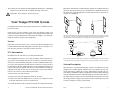
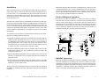
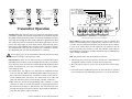
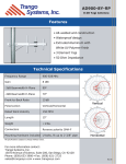
PTZ-900™ 900MHz Spread-Spectrum Digital Wireless Pan/Tilt/Zoom Camera Control Transmission System Installation and Operating Instructions THE LEADER IN WIRELESS VIDEO Quick-Start Guide 1 Prior to installing the wireless link, verify proper operation of PTZ controller (keyboard) and hard-wired receiver/driver or dome. M-PTZ_E.p65 All rights reserved. © 2002 Trango Systems, Inc. 15070 Avenue of Science, Suite 200 San Diego, California 92128 +1 858-653-3900 [email protected] www.trangosys.com 2 Determine the bit rate and interface (RS232 or RS485/422) of the hard-wired system. If it is not 9600 bps and RS485/422, you will need either to change the setting of the PTZ controller and receiver/driver or to change the settings of the PTZ-900 equipment. See the end of this manual for information on changing PTZ-900 internal settings using TrangoLink software. 3 Wire the terminal block with shielded twisted-pair cable as shown on pages 8 and 9. 4 After making the necessary adjustments to the internal settings and cables, connect the system as shown on page 4 and test the wireless link at short range to verify operation before installing permanently. 5 Install PTZ-900 transmitter and receiver units in desired locations to 23/8″ diameter steel pole and oriented as shown on page 3. The pole must be securely mounted so that it does not move. 6 Install antennas above the enclosures and position as shown on page 3. Important! The PTZ-900TX (transmitter) uses a special antenna connector. Use only the AD900-9-P or the AO900-3-P antenna, otherwise damage to the unit may occur. Use extreme care when installing antennas near power lines. You can be killed if the antenna comes in contact with the power line. . Do not apply power to the transmitter unless the antenna is connected. Permanent damage to the unit may result. The PTZ-900TX transmitter’s effective radiated output varies between 0.5 and 4 watts, depending on the transmit antenna used. Although transmissions are of a short duration, it is recommended that the transmit antenna be kept at least three feet away from nearby people. Important note to installer: This warning is for FCC exposure requirements. PTZ-900 Installation and Operating Instructions 7 Fasten the antenna cables to receiver and transmitter only fingertight (no more than 8 lb/in. of torque). Tighten flange around cables. Apply a small amount of silicone to the flange openings to make a leakproof connection. 8 Connect shielded twisted-pair interface cables to units through flanges. Tighten flanges. Important! Power adapter must be kept dry. 9 Verify that LED is illuminated, then tighten down the enclosure’s lid rev E Trango Systems, Inc. 3 10 To help protect against potential lightning damage use a lightning surge arrester in line with all cabling entering a structure. Important! Power Adapter must be kept dry. Important! Intentional or unintentional changes or modifications not expressly approved by the party responsible for compliance must not be made. Any such modifications could void the user's authority to operate the equipment. Your Trango PTZ-900 System Congratulations on choosing Trango Systems, Inc., to fulfill your wireless video needs. Unpack your system carefully. If any items are missing, notify your sales representative. If an item appears to be damaged from shipment, replace it in its packing material and notify the shipper. Save the packaging for further storage of the equipment. Since the patch antennas are directional, they must be aligned toward each other as shown. The AO900-3-P antenna is available for omnidirectional coverage, for which the receiver antenna must be vertically polarized by rotating it 90° from its normal position. Service AD900-9 AD900-9-P If the unit ever needs repair service, contact your dealer/distributor for return authorization and shipping instructions. Do not attempt to repair the unit yourself, as this may void the warranty. PTZ-900 TX (transmitter) PTZ-900 RX (receiver) DOME or RECEIVER DRIVER PTZ CONSOLE FCC Information shielded twisted pair (4000¢ maximum in RS-422 mode) ID number for the PTZ-900TX: FCC ID# NCYPTZ900TX This equipment generates, uses, and can radiate radio-frequency energy and, if not installed and used in accordance with these instructions, may cause harmful interference to radio communications. However, there is no guarantee that interference will not occur in a particular installation. If this equipment does cause harmful interference to radio or television reception (which can be determined by turning the equipment off and on) the user is encouraged to correct the interference by one of more of the following measures: 1 Reorient the receiving antenna; 2 Separate the affected equipment from the receiver; 3 Connect the affected equipment to an outlet on a different circuit from that which the receiver is connected to; shielded twisted pair (4000¢ maximum in RS-422 mode) Most common connection diagram for setting up a PTZ link using the PTZ-900-N system. The dome shown may instead be a standard receiver/driver unit with a separate PTZ base. System Description The PTZ-900 is a professional-quality wireless transmission system designed for sending digital, simplex (one-way) signals for pan, tilt, zoom and camera control up to twelve miles in line-of-sight. The system employs 900MHz frequency-hopping spread-spectrum technology with the maximum effective radiated output power allowed by the FCC for unlicensed operation. The system will operate interference-free with the Trango Falcon or Eagle series wireless video transmission systems to form a complete, wireless control link. 4 Consult the dealer and/or experienced radio/TV technician for help. 4 PTZ-900 Installation and Operating Instructions rev E Trango Systems, Inc. 5 Installation Make sure that you have tested the PTZ controller and receiver/driver/ dome using a direct connection (with wires) before installing the wireless link. Also, it is recommended that the wireless link be tested at short range before installing permanently. The transmitter and receiver units may get warm to the touch. This is normal and does not affect operation in any way. The PTZ-900 system is factory-configured for operation at 9600 bps, RS-485/422 mode, hopping sequence 0, address 0000. If your PTZ controller and dome operate at a speed other than 9600 bps or use RS-232 protocol, you must reprogram the PTZ-900TX and PTZ-900RX using the supplied programming cable and the TrangoLink software, which runs on any computer with Windows 95 or higher. See page 11 for detailed information. To obtain the best performance and transmission distance, the following rules of thumb should be followed: Important! The PTZ-900 enclosures are designed for a steel pole with a maximum diameter of 23/8″ and a wall thickness of ¼″. The pole must be securely mounted into the ground or to a structure to prevent movement of the antenna and camera in windy conditions. This pole also acts as an earth ground and must be grounded. Point-to-Multipoint Operation In some cases it may be necessary to control more than one camera from the same console. In this case, one PTZ-900TX transmitter can be used to send control signals to all receivers and the receiver/drivers will filter the data as in a hard-wired system. The user must ensure that all PTZ-900RX receivers have the same address and hopping sequence as the transmitter. Mount any antenna receiving from an AO900-3-P omnidirectional in the vertically polarized position. AO 900-3-P omni antenna PTZ-900TX 3 Do not add additional lengths of cable to connect the receiver to the antenna, as significant losses in signal and reduced transmission range will occur. 4 Keep the data link (shielded twisted-pair) cables as short as possible to prevent distortion of the data and possible interference with video running on coaxial cable nearby. The PTZ-900 system transmitter and receiver units come pre-mounted in a NEMA 4× aluminum enclosure. This permits the unit to be mounted outdoors. 6 PTZ-900 Installation and Operating Instructions FALCON or EAGLE TX for video PTZ900RX PTZ CONSOLE 1 Mount the transmitter and receiver antennas above human and mechanical traffic, the higher the better. A ten-foot steel mast on top of a building is typical. Make sure that the mast is well grounded to earth ground with a wire of AWG 8 or greater. For distances more than eight miles, the transmit and receive antennas must be fifteen to twenty feet above all obstacles in the line of sight. 2 Keep the transmission path as open as possible. Objects such as walls and metallic objects near the transmission path may reduce the transmission distance. Channel 1 FALCON or EAGLE RX for video Channel 3 MULTIPLEXER Channel 5 EVENT RECORDER MONITOR DOME or RECEIVER DRIVER Channel 7 Multilink Operation Different than point-to-multipoint operation. multilink is where more than one transmitter is operating in the same area. In this case, all the transmitters and receivers operating on one system would have the same hopping sequence and address. Those on another system nearby should have a different address and a different hopping sequence in order to add more isolation between the systems rev E Trango Systems, Inc. 7 AD900-9-P AD900-9 PTZ-900 TX (transmitter) AD900-9-P PTZ-900 TX (transmitter) PTZ-900 RX (receiver) HOPPING SEQUENCE #1 (ADDRESS 0001) HOPPING SEQUENCE #2 (ADDRESS 0002) LED DB9 PTZ CAMERA PTZ CAMERA PTZ CONSOLE AD900-9 PTZ-900 RX (receiver) PIN 5: GND (RS232) PIN 3: TD (RS232) or TX (RS485/422) PIN 2: RD (user mode only) PIN 7: TX+ (RS485/422) PTZ CONSOLE +7V GND TXD TX TX+ RXD RX RX+ Transmitter Operation Antenna jack. This connector is used to connect an appropriate Trango transmitter antenna. The antennas authorized for use with this unit are the AD900-9-P patch and the AO900-3-P omni. The maximum transmission range when using the omni will be reduced by approximately half. The connector used is custom and is somewhat fragile. Fasten the connector only finger-tight, no more than 8 lb/in. Important! The transmitter uses a non-standard jack to connect to the transmitter antenna. Any modification to this jack may void the user’s authority to operate the equipment and will void the manufacturer’s warranty. Do not apply power to the transmitter without the antenna securely attached. Damage to the unit may result. Data interfaces. There are two data interfaces: a terminal block and a male DB9 connector. Refer to the drawing below. In order to avoid damage to the unit, do not use both the terminal block and the DB9 for data output simultaneously. For more information, visit our website, www.trangosys.com. 1 Terminal block. Two lugs serve as the input for simplex data from 1200 to 19200 bps. When transmitting under RS485/422 protocols, data connections from the PTZ controller are made on TX+ and TX– of the terminal block. For RS232, the connections are to TXD and GND. The PTZ-900TX does not use the RX+ and RX– connectors. TERMINAL BLOCK POWER INPUT DATA INPUT (not used) The front panel of the PTZ-900TX transmitter. Power input. Accepts a power source between 6 and 13 volts DC. It is highly recommended that the supplied power adapters (7VDC) be used to reduce the heat dissipated from the unit. If another power adapter is to be used, ensure that it is well regulated (±5%). Batteries may be used as external power sources as well. The nominal current draw is 190 milliamperes when not sending commands and 522 milliamperes while sending commands. LED. The LED has three functional modes as follows: 1 Alternating green and red: The unit is waiting for a command from TrangoLink software (twenty seconds after startup only.) 2 Red: The unit is ready to receive data from the PTZ control equipment. 3 Green: The unit is sending data on the air. Since the data is typically sent out in bursts, the LED will be green for a very short time only. 2 DB9 connector. Attach the programming cable, CBLDAT-2, to this connector in order to use the TrangoLink set-up program. Refer to the instructions on page 11. This interface can also be used for connecting data input from a PTZ controller, but it might be difficult to close the unit while a cable is attached. 8 PTZ-900 Installation and Operating Instructions rev E Trango Systems, Inc. 9 Receiver Operation Antenna jack. This connector is used to connect an appropriate Trango receiver antenna. The antenna authorized for use with this unit is the AD900-9 patch. The connector used is an SMA type and is somewhat fragile. Tighten the connector only finger-tight, no more than 8 lb-in Power input. Accepts a power source between 6 and 13 volts DC. It is highly recommended that the supplied power adapters (7VDC) be used to reduce the heat dissipated from the unit. If another power adapter is to be used, ensure that it is well regulated (±5%). Batteries may be used as external power sources as well. The nominal current draw is 200 milliamperes. LED. The LED has three functional modes as follows: Data interfaces. There are two data interfaces: a terminal block and a male DB9 connector. Refer to the drawing on page 9. In order to avoid damage to the unit, do not use both the terminal block and the DB9 for data output simultaneously. For more information, visit our website, www.trangosys.com. 1 Alternating green and red: The unit is waiting for a command from TrangoLink (twenty seconds after startup only). 2 Red: The unit is ready to receive data from the PTZ-900TX transmitter. 3 Blinking green: The unit is receiving data. 1 Terminal block. Two lugs serve as the output for simplex data from 1200 to 19200 bps. When transmitting under RS485/422 protocols, data connections to the PTZ driver are made on RX+ and RX– of the terminal block. For RS232, the connections are to RXD and GND. The PTZ-900RX does not use the TX+ and TX– connectors. 2 DB9 connector. Attach the programming cable, CBLDAT-2, to this connector in order to run the TrangoLink set-up program. Refer to the instructions on page 11. This interface can also be used for connecting data output to a PTZ driver, but it might be difficult to close the unit while a cable is attached. PIN 5: GND (RS232) PIN 3: TD (user mode only) PIN 2: RD (RS232) or RX (RS485/422) PIN 8: RX+ (RS485/422) TrangoLink Software with the PTZ-900 System PC Requirements & Installation In order to run TrangoLink, you will need Windows 95 or higher, 400kB of free disk space, and one free 9-pin serial port. To install. The TrangoLink program, which can be found at our website at www.trangosys.com/, is a self-installing file. To install TrangoLink on your PC, simply download the file and double-click on it. LED DB9 To uninstall. Click on Start, then Settings, then Control Panel. Doubleclick on Add/Remove Programs. Select TrangoLink, and click Add/Remove +7V GND TXD TX TX+ RXD RX RX+ TERMINAL BLOCK POWER INPUT (not used) DATA OUTPUT The front panel of the PTZ-900RX receiver. 10 PTZ-900 Installation and Operating Instructions The TrangoLink program allows the user to change the user settings on the PTZ-900TX and PTZ-900RX. The program runs under Windows 95 or higher and connects from either COM1 or COM2 to the data interface on the transmitter or receiver via the CBLDAT-2 interface cable. To enter the program, the user must apply power to the PTZ-900 unit and, within twenty seconds, run the TrangoLink program by clicking on the TrangoLink icon. The LED will flash green and red until com. rev E Trango Systems, Inc. 11 munication is established. If a connection is not made within twenty seconds, the unit will exit programming mode and enter normal operating mode. In this event, simply reboot power to the unit and try again. After entering the program, a screen is displayed showing the current settings. The user may change the settings and then must click SAVE CHANGES AND EXIT. Upon exiting the program and cycling power to the unit, the settings will become effective. This screen offers the user five options. PN Sequence. The channel-hopping sequence must be the same on the transmitter and receiver in order for data to be transferred properly. RSSI. The Received Signal Strength Indicator is used for receiver to monitor the radio spectrum on all hopping channels. It is presented as a bar graph of power (dBm) against frequency (MHz). Useful in troubleshooting to determine if any other signals are present in the 900MHz band. Meaningless if connected to the PTZ-900TX. Data Rate. The rate for PTZ data can be set between 1200 and 19200 bps. Parity can be set to odd, even, or none. The settings must be the same on the transmitter and receiver. Mode. RS-232 (unbalanced) or RS-485/RS-422 (differential). Select the mode that matches your PTZ control equipment. Address. Multiple systems deployed in the same area should have different addresses. Similar to PN Sequence, the address setting must be the same on the transmitter and receiver in order for data to be transferred properly. You must click on SET ADDRESS to make changes effective Troubleshooting Interference or intermittent operation. 9 Heavy equipment such as industrial, roof-mounted air conditioners or fan motors in close proximity to the transmitter, receiver, or cables may cause interference, especially when operating in RS232 mode. Move the unit/cable away from the source of the interference. give the best results in general. 9 Raise transmitter and receiver antennas above ground and away from obstacles and traffic, including foot traffic. 9 Verify that all connectors are tight, especially the power connectors. 9 Shorten the receiver antenna feed cable. It is best to use only those cables supplied with the equipment. 9 If the system becomes unusable for a period of time on the order of minutes or hours and then becomes usable again, changing the PN sequence may cure the problem. The different PN sequences have different waiting channels that are used to synchronize the hopping sequences. Depending on your environment, there may be a 900MHz transmitter interfering on one of the waiting channels. By changing the PN sequence of the transmitter and receiver, the waiting channel will change. Some of the types of equipment that may interfere are 900MHz cordless phones and wireless LANs if they are very close to the PTZ-900RX receiver antenna. The waiting channels are 924.2MHZ (default) PN0, 905.8MHz PN3, 911.8MHz PN2, and 918.2MHz PN1. 9 High-power equipment operating near the 902–928MHz band, such as paging system base stations or cellular phone base stations, may also interfere if they are within several hundred feet of the receiver. Changing the PN sequence and reorienting the receiver antenna will most likely cure this type of interference. 9 The cable from transmitter to PTZ controller may be too long, corrupting digital data. Use category 5 twisted-pair shielded cable, if possible, and a maximum length of four thousand feet for RS422 or one hundred feet for RS232. 9 The cable from receiver to PTZ receiver/driver may be too long, corrupting digital data. Use category 5 twisted-pair shielded cable, if possible, and a maximum length of four thousand feet for RS422 or one hundred feet for RS232. 9 Antenna polarization may be wrong. The normal polarization for the AD900-9 antenna is horizontal, since that has been determined to 9 Interference on video signal when sending PTZ data. Check the system’s grounding and use ground-fault isolation transformers if the problem persists. 12 rev E PTZ-900 Installation and Operating Instructions Trango Systems, Inc. 13 Data not received. Parametric Specifications 9 Verify that a clear line of sight exists between the transmitter and receiver antennas for distances greater than five hundred feet. 9 Check that the transmit and receive PN sequences, data rate, mode, and address are set the same. 9 Verify that all connectors are tight. 9 Cycle the power. 9 Verify that transmitter and receiver antennas are aligned properly, as discussed above. Can’t communicate with transmitter or receiver using TrangoLink. Disconnect any peripherals connected to the terminal block. Plug the supplied programming cable, CBLDAT-2, into the system’s DB9. Power the computer on. Power the transmitter or receiver on, and within twenty seconds run the TrangoLink program from Windows. The LED will alternate between green and red to indicate that it is ready to talk to the TrangoLink software. Important! Do not use any other cable for this purpose. PTZ-900TX Transmitter: Electrical Radio Section Frequencies: 64 hopping frequencies, including the waiting channel, spaced by 400kHz starting at 902.2MHz Waiting Frequency, selectable: PN seq #0: 924.2 MHz PN seq #1: 918.2 MHz PN seq #2: 911.8 MHz PN seq #3: 905.8 MHz RF Output Power: nominal +27dBm ±0.5dBm conducted into 50Ω unmodulated carrier, final PA on. EIRP: +36dBm, 9dB patch antenna connected Frequency Stability: 0.0025% PLL-stabilized (25 ppm) over temperature range Frequency Plan: single up-conversion with pseudo-gaussian baseband filter for bandlimiting. High-side LO injection, 1052 MHz, Variable IF LO of 148.2 to 124.2 MHz with 400kHz channel spacing. Modulated Bandwidth: 67.5kHz (3dB); 112.5kHz (20dB) Harmonic Attenuation: > 20dBc (2nd harmonic) Spurious Attentuation: > 50 dBc Symbol Rate: 64.516 kbps Hopping Rate: 600 hops/sec Error Correction: rate 7,4 linear block coding Modulation: Gaussian-filtered FSK Data Input Section Buffer Size: 2 bytes Data Input Level: software-selectable between RS232 and RS485/422 (RS485/422 factory default) Data Rate (User): 1200, 2400, 4800, 9600, or 19200 bps user-configurable via TrangoLink (9600 factory default) Format: 8 data bits, no parity, 1 stop bit (even or odd parity is selectable) Level Limiting: none Input Impedance: 5kΩ unbalanced for RS232 mode 24kΩ otherwise. Power Section Input Voltage: 6–13VDC Current Consumption: 522 mA transmit, 190 mA standby PTZ-900TX Transmitter: Mechanical & Environmental General Material: Finish: Size: Weight: cast aluminum platinum powdercoat 4.65″W × 8.8″L × 2.475″D without antenna 2.65 lb Connectors and Indicators RF Output: reverse polarity SMA connector in compliance with FCC rules part 15C, 15.203. FCC Compliance: The transmitter complies with FCC Part 15.249, FCC Part 15.207(a). 14 PTZ-900 Installation and Operating Instructions rev E Serial Interface: DB9 male with ferrite or four-position terminal block Power: two-position terminal block Environmental Operating Temp.: –20ºC to 70ºC Storage: –30ºC to 85ºC Humidity: 100% condensing when installed properly Shock: sustains 3-axis drop from 5′ Trango Systems, Inc. 15 Parametric Specifications PTZ-900RX Receiver: Electrical Radio Section Frequencies: 902.2MHz to 927.8MHz Cascade Noise Figure: < 6dB Sensitivity for 10–6 BER: –95dBm max. Adj. Channel Rej: > 50dB Image Rejection: > 60dB Frequency Plan: double-conversion 1st IF at 110.6MHz, 2nd at 10.7MHz LO Stability: 0.0025% PLL-stabilized (25 ppm) over temperature range Input Compression Point: > –20dBm Data Output Section Buffer Size: 48 bytes Data Output Level: software-selectable rates between RS232 and RS485/422 (RS485/422 factory default) Data Rate (User): 1200, 2400, 4800, 9600, or 19200 bps user-configurable via TrangoLink (9600 factory default) Format: 8 data bits, no parity, 1 stop bit (even or odd parity is selectable) Level limiting: none Input Impedance: 6kΩ balanced Max. Output Loading: 3kΩ, 2500pF Power Section Input Voltage: 6–13VDC Current Consumption: 200mA PTZ-900RX Receiver: Mechanical & Environmental General Material: Finish: Size: Weight: cast aluminum platinum powdercoat 4.65″W × 8.8″L × 2.475″D without antenna 2.65 lb Connectors and Indicators RF Output: SMA-F connector FCC Compliance: The receiver complies with FCC Part 15.299 and FCC Part 15.207(a) Serial Interface: DB9 male with ferrite or four-position terminal block Power: two-position terminal block Environmental Operating Temp. : –20ºC to 70ºC Storage: –30ºC to 85ºC Humidity: 100% condensing when installed properly Shock: sustains 3-axis drop from 5′ Trango Systems technical support online: www.trangosys.com voice: +1 858-653-3900 16 PTZ-900 Installation and Operating Instructions rev E Trango Systems, Inc. 17