1
Air Conditioning
Clinic
Refrigeration
System Components
One of the Fundamental Series
TRG-TRC005-EN
Perforation 0.75” from edge
Comment Card
We want to ensure that our educational materials meet your ever-changing resource development needs.
Please take a moment to comment on the effectiveness of this Air Conditioning Clinic.
Refrigeration System
Components
Level of detail (circle one)
One of the Fundamental Series
Rate this clinic from 1–Needs Improvement to 10–Excellent…
TRG-TRC005-EN
Content
1
2
3
4
5
6
7
8
9
10
Booklet usefulness
1
2
3
4
5
6
7
8
9
10
Slides/illustrations
1
2
3
4
5
6
7
8
9
10
Presenter’s ability
1
2
3
4
5
6
7
8
9
10
Training environment
1
2
3
4
5
6
7
8
9
10
Too basic
Just right
Too difficult
Other comments?
_________________________________________________________
_______________________________________________________________________________
_______________________________________________________________________________
About me … Type of business
Job function
Optional:
name
phone
address
_________________________________________________________
_________________________________________________________
_________________________________________________________
_________________________________________________________
_________________________________________________________
Give the completed card to the
presenter or drop it in the mail.
Thank you!
The Trane Company • Worldwide Applied Systems Group
3600 Pammel Creek Road • La Crosse, WI 54601-7599
www.trane.com
An American-Standard Company
Perforation 5.5” from bottom/top
Response Card
We offer a variety of HVAC-related educational materials and technical references, as well as software tools
that simplify system design/analysis and equipment selection. To receive information about any of these
items, just complete this postage-paid card and drop it in the mail.
Education materials
Software tools
Periodicals
Other?
❏ Air Conditioning Clinic series
❏ Engineered Systems Clinic series
❏ Trane Air Conditioning Manual
❏ Trane Systems Manual
❏ Equipment Selection
❏ System design & analysis
❏ Engineers Newsletter
❏ _____________________________
About me…
Name
___________________________________________
Title
___________________________________________
Business type ___________________________________________
Phone/fax
_____________________
____________________
E-mail address ___________________________________________
Company
___________________________________________
Address
___________________________________________
___________________________________________
___________________________________________
Thank you for your interest!
The Trane Company • Worldwide Applied Systems Group
3600 Pammel Creek Road • La Crosse, WI 54601-7599
www.trane.com
An American-Standard Company
NO POSTAGE
NECESSARY
IF MAILED
IN THE
UNITED STATES
BUSINESS REPLY MAIL
FIRST-CLASS MAIL
PERMIT NO. 11
LA CROSSE, WI
POSTAGE WILL BE PAID BY ADDRESSEE
Crop to width of 7.75”
THE TRANE COMPANY
Attn: Applications Engineering
3600 Pammel Creek Road
La Crosse WI 54601-9985
NO POSTAGE
NECESSARY
IF MAILED
IN THE
UNITED STATES
BUSINESS REPLY MAIL
FIRST-CLASS MAIL
PERMIT NO. 11
LA CROSSE, WI
POSTAGE WILL BE PAID BY ADDRESSEE
THE TRANE COMPANY
Attn: Applications Engineering
3600 Pammel Creek Road
La Crosse WI 54601-9985
Refrigeration
System Components
One of the Fundamental Series
A publication of
The Trane Company—
Worldwide Applied Systems Group
Preface
Refrigeration
System Components
A Trane Air Conditioning Clinic
Figure 1
The Trane Company believes that it is incumbent on manufacturers to serve the
industry by regularly disseminating information gathered through laboratory
research, testing programs, and field experience.
The Trane Air Conditioning Clinic series is one means of knowledge-sharing. It
is intended to acquaint a nontechnical audience with various fundamental
aspects of heating, ventilating and air conditioning. We have taken special care
to make the clinic as uncommercial and straightforward as possible.
Illustrations of Trane products only appear in cases where they help convey the
message contained in the accompanying text.
This particular clinic introduces the reader to the concept of vapor-compression
refrigeration system components.
ii
© 1999 American Standard Inc. All rights reserved
TRG-TRC005-EN
Contents
Introduction ........................................................... 1
period one
Refrigeration Cycle .............................................. 2
period two
Condensers ............................................................ 5
Air-Cooled Condensers .............................................. 5
Evaporative Condensers ............................................ 7
Water-Cooled Condensers ......................................... 8
Condenser Control ................................................... 10
period three Evaporators .......................................................... 16
Finned-Tube Evaporators ......................................... 16
Shell-and-Tube Evaporators ...................................... 19
Evaporator Control ................................................... 20
period four
Expansion Devices ............................................. 26
period five
Accessories .......................................................... 34
Solenoid Valve .......................................................... 34
Liquid-Line Filter Drier .............................................. 36
Moisture-Indicating Sight Glass ............................... 38
Suction Line Filter .................................................... 39
Hot Gas Muffler ....................................................... 40
Shutoff Valve ............................................................ 41
Access Port .............................................................. 42
period six
Review ................................................................... 43
Quiz ......................................................................... 48
Answers ................................................................ 50
Glossary ................................................................ 51
TRG-TRC005-EN
iii
iv
TRG-TRC005-EN
Introduction
notes
Vapor-Compression Refrigeration
condenser
expansion
device
compressor
evaporator
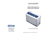
Figure 2
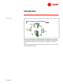
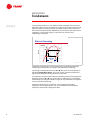
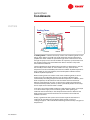
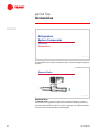
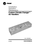
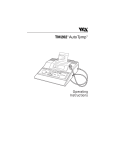
The major components of a vapor-compression refrigeration system include
the compressor, condenser, expansion device, and evaporator. The latter three
will be discussed in this clinic—the compressor is discussed in a separate
clinic.
This clinic will also discuss many of the common accessories used in a comfortcooling refrigeration system.
TRG-TRC005-EN
1
period one
Refrigeration Cycle
notes
Refrigeration
System Components
period one
Refrigeration Cycle
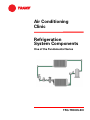
Figure 3
First, a brief review of the vapor-compression refrigeration cycle will help to
relate these components.
pressure
Refrigeration Cycle
A
evaporator
enthalpy
B
Figure 4
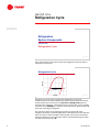
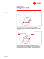
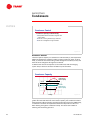
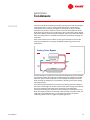
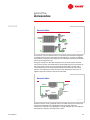
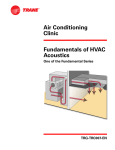
A diagram of a typical vapor-compression refrigeration cycle can be
superimposed on a pressure-enthalpy (P-h) chart to demonstrate the function
of each component in the system. The pressure-enthalpy chart plots the
properties of a refrigerant—refrigerant pressure (vertical axis) versus enthalpy
(horizontal axis). Enthalpy is a measure of the heat content, both sensible and
latent, per pound [kg] of refrigerant.
The cycle starts with a cool, low-pressure mixture of liquid and vapor
refrigerant entering the evaporator (A) where it absorbs heat from the relatively
warm air, water, or other fluid that is being cooled. This transfer of heat boils
the liquid refrigerant in the evaporator, and this superheated refrigerant vapor
is drawn to the compressor (B).
2
TRG-TRC005-EN
period one
Refrigeration Cycle
notes
Refrigeration Cycle
pressure
C
compressor
A
evaporator
B
enthalpy
Figure 5
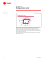
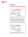
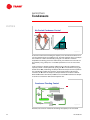
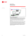
The compressor draws in the superheated refrigerant vapor (B) and
compresses it to a pressure and temperature (C) high enough that it can reject
heat to another fluid. This hot, high-pressure refrigerant vapor then travels to
the condenser.
Refrigeration Cycle
condenser
C
pressure
D
compressor
A
evaporator
enthalpy
B
Figure 6
Within the condenser, heat is transferred from the hot refrigerant vapor to
relatively cool ambient air or cooling water. This reduction in the heat content
of the refrigerant vapor causes it to desuperheat, condense into liquid, and
further subcool before leaving the condenser (D) for the expansion device.
TRG-TRC005-EN
3
period one
Refrigeration Cycle
notes
Refrigeration Cycle
pressure
D
condenser
C
expansion
device
A
compressor
evaporator
enthalpy
B
Figure 7
Finally, the high-pressure liquid refrigerant (D) flows through the expansion
device, causing a large pressure drop that reduces the pressure of the
refrigerant to that of the evaporator. This pressure reduction causes a small
portion of the liquid to boil off, or flash, cooling the remaining refrigerant to the
desired evaporator temperature.
The cooled mixture of liquid and vapor refrigerant then enters the evaporator
(A) to repeat the cycle.
4
TRG-TRC005-EN
period two
Condensers
notes
Refrigeration
System Components
period two
Condensers
Figure 8
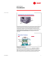
The first major component to be discussed is the condenser. The condenser is
a heat exchanger that rejects heat from the refrigerant to air, water, or some
other fluid.
The three common types of condensers are air-cooled, water-cooled, and
evaporative.
Air-Cooled Condenser
propeller
fan
outdoor
air
condenser
coil
subcooler
Figure 9
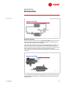
Air-Cooled Condensers
A typical air-cooled condenser uses propeller-type fans to draw outdoor air
over a finned-tube heat transfer surface. The temperature difference between
the hot refrigerant vapor that is flowing through the tubes and the cooler
outdoor air induces heat transfer. The resulting reduction in the heat content of
the refrigerant vapor causes it to condense into liquid. Within the final few
lengths of condenser tubing (the subcooler), the liquid refrigerant is further
cooled below the temperature at which it was condensed.
TRG-TRC005-EN
5
period two
Condensers
notes
The air-cooled condenser is very popular in both residential and commercial
applications because of its convenience. It requires very little maintenance and
does not require the freeze protection and water treatment that is necessary
with a water-cooled condenser. Additionally, it is favored in areas that have an
inadequate or costly water supply, or where the use of water for air
conditioning is restricted.
Effect of Subcooling
D
C
{
pressure
subcooling
DI
AI
A
B
refrigeration
effect
enthalpy
Figure 10
The benefit of subcooling on system performance can be demonstrated by
comparing the performance of a system with and without subcooling.
The change in enthalpy (the line from A to B) that occurs in the evaporator is
called the refrigeration effect. This is the amount of heat that each pound
[kg] of liquid refrigerant will absorb when it evaporates.
In comparison, the same system without subcooling produces less refrigeration
effect (the line from A’ to B). The system without subcooling must evaporate
substantially more refrigerant within a larger coil to produce the same capacity
as the system with subcooling.
Instead of subcooling in the condenser, some packaged refrigeration
equipment, such as water chillers, may use an economizer or liquid/vapor
separator to increase this refrigeration effect.
6
TRG-TRC005-EN
period two
Condensers
notes
Centrifugal Fan Air-Cooled Condenser
condenser
coil
centrifugal
fan
Figure 11
An alternative air-cooled condenser uses a centrifugal fan to draw or blow air
over the condensing coil. The principal advantage of this design is that the
centrifugal fan is capable of overcoming the higher static-pressure losses
associated with ductwork. Therefore, if the condenser is to be located indoors
and uses a duct system to deliver air to and from the condenser coil, the
centrifugal fan air-cooled condenser is probably best suited for this
application.
Evaporative Condenser
fan
refrigerant
vapor
condenser
coil
pump
sump
liquid refrigerant
subcooler
Figure 12
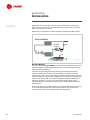
Evaporative Condensers
A modification of the air-cooled condenser is the evaporative condenser.
Within this device, the refrigerant flows through tubes and air is drawn or
blown over the tubes by a fan. The difference is that water is sprayed on the
tube surfaces. As the air passes over the coil, it causes a small portion of the
water to evaporate. This evaporation process absorbs heat from the coil,
TRG-TRC005-EN
7
period two
Condensers
notes
causing the refrigerant vapor within the tubes to condense. The remaining
water then falls to the sump to be recirculated and used again.
Subcooling of the refrigerant can be accomplished by piping the condensed
liquid back through another few rows of coil tubing, located either in the
condenser airstream or in the water sump, where additional heat transfer
reduces the temperature of the liquid refrigerant.
Water-Cooled Condenser
95ºF
hot, refrigerant vapor
[35ºC]
cooling water
85ºF
[29ºC]
subcooled,
subcooled, liquid
refrigerant
subcooler
Figure 13
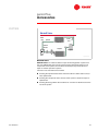
Water-Cooled Condensers
The shell-and-tube is the most common type of water-cooled condenser.
With this design, water is pumped through the tubes while the refrigerant vapor
fills the shell space surrounding the tubes. As heat is transferred from the
refrigerant to the water, the refrigerant vapor condenses on the tube surfaces.
The condensed liquid refrigerant then falls to the bottom of the shell, where it
flows through an enclosure that contains additional tubes (the subcooler). More
heat is transferred from the liquid refrigerant to the water inside these tubes,
subcooling the refrigerant.
After the warm water leaves the condenser, it must either be disposed of (as in
the case of using water from a well) or it must be cooled before it can be reused
by the condenser. In this example, the condenser brings in 85°F [29°C] water
and warms it up to 95°F [35°C]. Before this water can be used again, it must be
cooled back down to 85°F [29°C].
8
TRG-TRC005-EN
period two
Condensers
notes
Cooling Tower
propeller
fan
sprays
fill
outdoor
air
sump
85ºF
[29ºC]
to
condenser
from
condenser
95ºF
[35ºC]
Figure 14
A cooling tower is a device commonly used to cool condensing water. In this
design, warm water is sprayed over the fill inside the cooling tower while a
propeller fan draws outdoor air upward through the fill. The movement of air
through the spray causes some of the water to evaporate, a process that cools
the remaining water. This cooled water then falls to the tower sump to be
returned to the condenser.
The final temperature of the water leaving the tower is determined, in part, by
the humidity of the outdoor air. If the outdoor air is dry, the final water
temperature can be considerably lower than the ambient dry-bulb temperature.
If the outdoor air is humid, however, the final temperature will be near the
ambient dry-bulb temperature.
While a cooling tower can reclaim much of the condensing water, it cannot
reclaim it all. The evaporation process uses up water to dissipate heat
contributed by the cooling load plus the heat of compression. In addition, as the
water evaporates, the dissolved minerals and water treatment chemicals
become concentrated in the sump. To prevent this solution from becoming
concentrated and possibly corrosive, water is periodically bled from the sump
and an equal amount of fresh water is added.
In the past, some water-cooled condensers used water from either a municipal
or a natural water supply as the condensing water. After rejecting the
condenser heat to this water, it was dumped into the sewer or back into the
body of water. Environmental and economic restrictions have made this
method uncommon.
Finally, a geothermal well system can be used to reject the heat from the
condenser by circulating the condensing water through a series of
underground pipes . This method takes advantage of the naturally-cool ground
temperatures.
TRG-TRC005-EN
9
period two
Condensers
notes
Condenser Control
I
Condenser capacity is influenced by:
K Temperature
difference between refrigerant and
cooling media
K Flow
rate of cooling media through condenser
K Flow
rate of refrigerant through condenser
Figure 15
Condenser Control
The heat rejection capacity of a condenser is influenced by (1) the temperature
difference between the refrigerant and the cooling media (air, water, or other
fluid), (2) the flow rate of the cooling media through the condenser, and (3) the
flow rate of the refrigerant through the condenser.
To balance the rate of heat rejection (in the condenser) with the changing
system load, at least one of these variables may be controlled.
Condenser Capacity
full load
condenser heat
rejection capacity
pressure
full load
part load
condenser heat
rejection capacity
part load
enthalpy
Figure 16
As the system load decreases, the heat rejection capacity of the condenser is
greater than the load. Because of this excess capacity, the condenser matches
the decreasing load by operating at progressively lower pressures. Additionally,
a reduction in outdoor air temperature allows the temperature of the air or
water flowing through the condenser to drop. This also has the effect of
lowering the condensing pressure.
10
TRG-TRC005-EN
period two
Condensers
notes
A reduction in condensing pressure lessens the power required to compress
the refrigerant. Unfortunately, if the condensing pressure falls too low, the
expansion valve may not be able to produce the flow of liquid refrigerant
needed to satisfy the demand at the evaporator. In some systems, as the
condensing pressure drops, the compressor suction pressure also drops,
resulting in evaporator frosting and possible compressor shutdown due to a
low-pressure safety device.
While it is not essential to control condensing pressure to a constant value,
provisions should be made to control it within acceptable limits.
Condensing Temperature Control
flow-regulating
valve
condenser
condenser
water pump
Figure 17
One common method of controlling the capacity of a water-cooled condenser is
to vary the rate at which water flows through the condenser.
For example, assume a water-cooled condenser is piped to a municipal water
system. To control the capacity of the condenser, a flow-regulating valve is
installed on the leaving-water side of the condenser. As the load on the system
decreases, the regulating valve senses the lowering condensing pressure. The
valve reduces the flow rate of the water until the heat-rejection rate of the
condenser balances the system load at an acceptable pressure and
temperature.
TRG-TRC005-EN
11
period two
Condensers
notes
Vary Condenser Water Flow Rate
cooling tower
cooling tower
condenser
variable-speed
drive
diverting
valve
bypass pipe
condenser
Figure 18
It is more common, however, for a water-cooled condenser to be connected to a
cooling tower.
In this case, typical methods for modulating the water flow through the
condenser include either using a variable-speed drive on the condenser water
pump or using a diverting valve and pipe to bypass the condenser. The
variable-speed drive on the pump modulates the amount of water pumped
through the condenser. The diverting valve modulates the water flow through
the condenser bundle by diverting some of the cooling water around the
condenser through the bypass pipe, directly back to the cooling tower.
Each of these options has the effect of varying the flow rate of water through
the condenser, ensuring an acceptable condensing pressure and temperature.
Vary Entering Water Temperature
variablespeed
drive
cooling tower
cooling tower
condenser
bypass pipe
diverting
valve
condenser
Figure 19
Another method of controlling the capacity of a water-cooled condenser is to
vary the temperature of the water entering the condenser.
12
TRG-TRC005-EN
period two
Condensers
notes
Common methods of modulating this water temperature include controlling the
cooling tower fans or using a cooling-tower bypass pipe. Controlling the
cooling tower fans, either by cycling fans on and off or by using a variablespeed drive on the fans, allows the system to control the temperature of the
water leaving the tower sump. The diverting valve on the cooling-tower bypass
pipe diverts warmer water leaving the condenser and mixes it with cooler water
from the cooling tower to modulate the temperature of the water entering the
condenser.
Each of these options has the effect of varying the temperature of the water
entering the condenser, ensuring an acceptable condensing pressure and
temperature.
Cooling Tower Bypass
40ºF
[4ºC]
cooling tower
bypass pipe
55ºF
diverting
valve
65ºF
[13ºC]
[18ºC]
condenser
Figure 20
Another example is a system that must start and operate during cooler weather.
The cold tower water would force the condensing pressure down to the point
where the system could not operate. In this example, the temperature of the
water entering the condenser is controlled by a diverting valve and a coolingtower bypass pipe.
If the entering water temperature causes the condensing pressure to become
too low, the valve begins to divert the warm water that is leaving the condenser
and mixes it with the cool tower water, producing a controlled water
temperature entering the condenser. In this example, by diverting 65°F [18°C]
water leaving the condenser and mixing it with the 40°F [4°C] tower water, the
condenser is provided with 55°F [13°C] condensing water. This warmer
condensing water results in a higher condensing pressure.
TRG-TRC005-EN
13
period two
Condensers
notes
Air-Cooled Condenser Control
A
B
condenser airflow
damper
fan A
fan B
fan A
heat rejection capacity
Figure 21
A common method of controlling the capacity of an air-cooled condenser is to
vary the airflow across the condenser coil. The heat-rejection rate of a multiplefan condenser is often controlled by cycling fans on and off to maintain
acceptable condensing pressures. Alternatively, the airflow across the coil can
be varied by using a damper or a variable-speed drive on one or more of the
fans.
In this example, a damper has been added to one of the two condenser fans.
Capacity control is accomplished by cycling fan B on and off while varying the
airflow of fan A by modulating the damper. Both the damper and the cycled fan
are controlled by condensing pressure. As the heat-rejection requirement
increases, fan A continues to open its damper farther to increase its airflow.
When fan A reaches full airflow, fan B turns on and fan A modulates its damper
to continue to match the desired heat rejection rate.
Condenser Flooding Control
condenser
B
C
A
liquid receiver
expansion
valve
evaporator
discharge line
compressor
Figure 22
Another, less common method of controlling the capacity of an air-cooled
14
TRG-TRC005-EN
period two
Condensers
notes
condenser is to flood the condenser coil with liquid refrigerant. A condenser
coil tube that is filled with liquid refrigerant no longer acts as a condensing
surface. Progressive flooding of the condenser coil tubes reduces the capacity
of the condenser and raises the condensing pressure.
During normal, warm ambient conditions, valves B and C are open and valve A
is closed. Assume that the system load is falling and, at the same time, the
outdoor air temperatures has fallen to the point where the rate of heat rejection
from the condenser balances the load at a condensing pressure less than
desired. This minimum condensing pressure is the set point for valve A. As the
condensing pressure decreases, so does the pressure in the discharge line.
Valve B acts as a pressure regulator, and when the discharge-line pressure falls
below its set point, valve B closes.
This causes the condensing pressure to drop farther. Sensing this reduction in
condensing pressure, valve A opens and directs hot, high-pressure refrigerant
vapor into the receiver. This increases the pressure in the receiver, controlling it
to the desired condensing pressure. Because the pressure in the receiver is now
higher than the pressure in the condenser, the check valve C does not allow the
refrigerant to flow back into the condenser.
With valve B closed and valve A modulating to maintain the pressure in the
receiver, the pressure in the discharge line begins to increase. When it exceeds
the set point for valve B, the valve opens and again allows hot refrigerant vapor
into the condenser. However, since the condensing pressure is still below the
pressure in the receiver, the refrigerant cannot flow through valve C. This
causes the condensed liquid to remain in the condenser, where it backs up, or
floods, the condenser tubes.
The flooding of tubes causes the condenser to progressively lose capacity.
When it has flooded enough that its capacity is reduced to the point where the
condensing pressure rises above the pressure in the receiver, the higherpressure condensed liquid will flow through check valve C into the receiver.
This increases the pressure in the receiver above the minimum condensing
pressure set point, closing valve A.
Condenser coil flooding provides the capacity modulation range needed to
produce acceptable condensing pressures at reduced loads and
correspondingly-low outdoor temperatures.
TRG-TRC005-EN
15
period three
Evaporators
notes
Refrigeration
System Components
period three
Evaporators
Figure 23
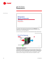
The second major component to be discussed is the evaporator. The
evaporator is a heat exchanger that transfers heat from air, water, or some
other fluid to the cool liquid refrigerant.
Two common types of evaporators are the finned-tube and the shell-and-tube.
Finned-Tube Evaporator
liquid/vapor
refrigerant
airflow
refrigerant vapor
Figure 24
Finned-Tube Evaporators
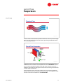
A finned-tube evaporator includes rows of tubes passing through sheets of
formed fins. Cool, liquid refrigerant flows through the tubes, cooling the tube
and fin surfaces. As air passes through the coil and comes into contact with the
cold fin surfaces, heat is transferred from the air to the refrigerant. This heat
transfer causes the refrigerant to boil and leave the evaporator as vapor.
16
TRG-TRC005-EN
period three
Evaporators
notes
Turbulent Flow
Figure 25
The fins of the coil are formed to produce turbulence as the air passes through
them. This turbulence enhances heat transfer, preventing stratification within
the coil-leaving airstream.
Finned-Tube Evaporator
liquid/vapor
refrigerant
airflow
liquid
distributor
suction
header
refrigerant vapor
Figure 26
To provide uniform heat transfer throughout the coil, the liquid refrigerant is
distributed to the coil tubes in several parallel circuits. A distributor is used to
ensure uniform refrigerant distribution through these multiple coil circuits. It
distributes the liquid/vapor refrigerant mixture to the coil through several tubes
of equal length and diameter.
As the refrigerant passes through the tubes of the coil, the liquid refrigerant
absorbs heat from the air, causing it to boil off into vapor. The refrigerant vapor
leaves the coil tubes and collects in a suction header.
TRG-TRC005-EN
17
period three
Evaporators
notes
Each distributor has an allowable range of refrigerant flow rates that define its
stable operating range. As the size of the evaporator coil increases, it may be
necessary to use more than one distributor to feed liquid refrigerant to the coil.
Superheat
B
A
C
{
B
A
C
superheat
Figure 27
Inside the final length of tubes—the location where the temperature difference
between the refrigerant and the air is highest—this larger temperature
difference accelerates the rate of heat transfer and the refrigerant vapor
absorbs even more heat. When the liquid refrigerant has completely
evaporated, this additional heat gain to the vapor is called superheating.
Superheating the refrigerant vapor (the line from B to C) shifts it away from the
liquid/vapor region and ensures that the refrigerant vapor is completely free of
liquid prior to traveling to the compressor.
18
TRG-TRC005-EN
period three
Evaporators
notes
Shell-and-Tube Evaporator
chilled
water
supply
baffles
chilled
water
return
refrigerant
vapor
tube bundle
liquid/vapor
refrigerant
Figure 28
Shell-and-Tube Evaporators
Instead of producing cooled air, a shell-and-tube evaporator is used to
produce chilled water. In this type of evaporator, the cool liquid refrigerant
flows through the tubes and water fills the shell space surrounding the tubes.
As heat is transferred from the water to the refrigerant, the refrigerant boils
inside the tubes and the resulting vapor is drawn to the compressor. Water
enters the shell at one end and leaves at the opposite end.
This chilled water is pumped to one or more heat exchangers to handle the
system cooling load. These heat exchangers could be coils used to cool air or
they could be some other load that requires chilled water.
Shell-and-Tube Evaporator
baffles
Figure 29
Baffles within the shell direct the water in a rising and falling flow path over the
tubes that carry the refrigerant. This results in turbulence that improves heat
transfer.
TRG-TRC005-EN
19
period three
Evaporators
notes
Evaporator Control
I
Evaporator capacity is influenced by:
K Temperature
difference between refrigerant and air or
water being cooled
K Flow
rate of air or water through evaporator
K Flow
rate of refrigerant through evaporator
Figure 30
Evaporator Control
The rate of heat exchange within an evaporator is governed by (1) the
temperature difference between the refrigerant and the air or water being
cooled, (2) the flow rate of the air or water through the evaporator, and (3) the
flow rate of the refrigerant through the evaporator.
In comfort-cooling applications, it is necessary to balance the capacity of the
system with the ever-changing load. The flow rate and temperature of the air or
water being cooled are typically controlled to respond directly to the system
load. A constant-volume system delivers a constant quantity of air to the space
and, to maintain the required space temperature at all load conditions, varies
the temperature of this air. In contrast, a variable-air-volume (VAV) system
delivers air at a constant temperature and varies the airflow to maintain the
required space temperature at all load conditions.
These are variables that the evaporator must respond to rather than directly
control. The most common method of controlling the capacity of the evaporator
at part load is to control the temperature and/or flow rate of the refrigerant
through the system by unloading or cycling compressors. To provide stable
part-load operation and balance compressor unloading with the capacity of the
evaporator, some direct form of evaporator capacity control may also be
required.
20
TRG-TRC005-EN
period three
Evaporators
notes
Finned-Tube Evaporator Control
expansion
valve
evaporator
liquid
refrigerant
refrigerant
vapor
Figure 31
Typically, an expansion valve is used to control the flow rate of refrigerant
through the evaporator to maintain the proper amount of superheat, ensuring
that the liquid refrigerant will be completely vaporized. Working in conjunction
with the unloading or cycling compressors, the expansion valve allows the
evaporator capacity to match the system load. The operation of the expansion
valve will be discussed further in Period Four.
Face-Split Arrangement
distributors
Figure 32
When an evaporator contains more than one liquid-refrigerant distributor, it is
split into independently-controlled sections, each being served by its own
expansion valve. By turning on and shutting off these coil sections, the
evaporator can further control its capacity to better match the system load.
The three common arrangements for splitting finned-tube evaporator coils
include: face-split, intertwined, and row-split.
TRG-TRC005-EN
21
period three
Evaporators
notes
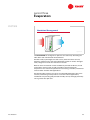
The face-split coil configuration, also called horizontal-split or parallel-flow, is
split into parallel sections. A portion of the air passes through the top section,
the remainder passes through the bottom section, and the two airstreams mix
downstream of the coil.
Face-Split Arrangement
e coil 80ºF
inactiv
[27ºC]
oil
ve c
acti
55ºF
[13ºC]
80ºF
[27ºC]
30ºF
[-1.1ºC]
Figure 33
At lower loads, only one section of the face-split coil is active. A portion of the
air passes through the active lower section and is cooled, while the rest of the
air passes through the inactive top section and remains unconditioned. The two
airstreams mix downstream of the coil, producing average temperature and
humidity conditions. At higher loads, both sections of the coil are activated,
providing a more uniform leaving-air temperature.
In a VAV application, where the leaving air is controlled to a constant
temperature, the active section of coil must supply colder air than the desired
average temperature at part load. Consequently, the refrigerant must get colder
at part load, eventually reaching a condition where the coil surface is cold
enough that the water condensing from the air will create frost on the coil.
Resetting the supply air temperature upward can help to avoid this problem,
but this may result in space humidity problems.
In constant-volume applications, where the leaving-air temperature varies to
respond to changing loads, this is not as much of a concern since the average
mixed temperature rises at part-load conditions. Therefore, face-split coils are
well suited for constant-volume applications. They provide better part-load
humidity control than could be obtained from a large coil controlled by a single
expansion valve. In a constant-volume application, the lower section of a facesplit coil should be activated first and deactivated last. This sequence prevents
moisture that has condensed from the air flowing through the active coil
section from flowing over the fins of the inactive coil section, where it could
carry over into the supply airstream.
22
TRG-TRC005-EN
period three
Evaporators
notes
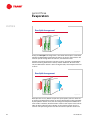
Intertwined Arrangement
Figure 34
The intertwined coil configuration splits the coil sections by alternating the
tubes fed in each row between two distributors.
At lower loads, liquid refrigerant is fed to every other tube of the coil and,
therefore, it behaves like a coil with substantially greater fin surface. At higher
loads, refrigerant is fed to all of the tubes in the coil.
Because of the increased fin surface available at part-load conditions, the coil
surface does not have to be as cold to provide a constant leaving-air
temperature. This reduces the potential for coil frosting. Therefore, intertwined
coils are better suited for VAV applications.
Part-load humidity control is less of an issue with VAV applications due to the
constant, cold leaving-air temperature. In constant-volume applications,
intertwined coils provide good part-load humidity control, although potentially
not as good as face-split coils.
TRG-TRC005-EN
23
period three
Evaporators
notes
Row-Split Arrangement
Figure 35
Finally, the row-split coil configuration, also called vertical-split or series-flow,
places the independently-controlled coil sections in series in the airstream. All
of the air passes through both coil sections, one before the other.
Typically, the first few upstream rows of the coil are served by one distributor,
and the remaining downstream rows by another distributor. At lower loads,
only the downstream section is active. At higher loads, the full depth of the coil
is active.
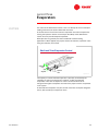
Row-Split Arrangement
70ºF
[21ºC]
80ºF
[27ºC]
55ºF
[13ºC]
Figure 36
Row-split coils are very difficult to split into equal-capacity sections. Since the
air entering the downstream section of coil has already been cooled somewhat
by the upstream section of coil, the air-to-refrigerant temperature difference is
much smaller. Therefore, the downstream section of coil requires more rows of
tubes to deliver about the same capacity as the upstream section of coil. A
common row-split arrangement uses two rows for the upstream section and
24
TRG-TRC005-EN
period three
Evaporators
notes
four rows for the downstream section. This is an attempt to ensure near-equal
loading of the two coil sections when both are active.
A second concern involves the control of superheat. The cooler temperatures
leaving the upstream section of coil hamper the ability of the downstream
section of coil to provide adequate superheat.
Row-split coils are generally not recommended for comfort-cooling
applications. When applied, they require careful coil selection, expansion valve
sizing and selection, and control.
Shell-and-Tube Evaporator Control
shell-and-tube
evaporator
refrigerant
vapor
liquid
refrigerant
expansion
valve
Figure 37
The capacity of a shell-and-tube evaporator is primarily controlled by the
unloading or cycling of compressors. However, as with a finned-tube
evaporator, it also uses an expansion valve to control the flow rate of
refrigerant through the evaporator and ensure the proper amount of superheat
in the system.
A shell-and-tube evaporator may also contain more than one liquid refrigerant
circuit, each served by one expansion valve.
TRG-TRC005-EN
25
period four
Expansion Devices
notes
Refrigeration
System Components
period four
Expansion Devices
Figure 38
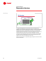
The final major component to be discussed is the expansion device.
Expansion Device
pressure
D
condenser
C
expansion
device
A
compressor
evaporator
enthalpy
B
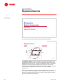
Figure 39
An expansion device is used to maintain a pressure difference between the
high-pressure (condenser) and low-pressure (evaporator) sides of the system
established by the compressor. This pressure difference allows the evaporator
temperature to be low enough to absorb heat from the air or water to be
cooled, while also allowing the refrigerant to be at a high enough temperature
in the condenser to reject heat to air or water at normally available
temperatures.
There are several types of expansion devices, including expansion valves
(thermostatic or electronic), capillary tubes, and orifices. This clinic will limit its
discussion to thermostatic expansion valves (TXVs). Other expansion devices
perform essentially the same function.
26
TRG-TRC005-EN
period four
Expansion Devices
notes
Thermostatic Expansion Valve
thermostatic
expansion
valve (TXV)
evaporator
liquid/vapor
mixture
liquid
refrigerant
A
refrigerant
vapor
Figure 40
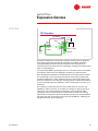
In addition to maintaining a pressure difference, the thermostatic expansion
valve controls the quantity of liquid refrigerant entering the evaporator. It
ensures that the refrigerant will be completely vaporized within the evaporator
(A) and maintains the proper amount of superheat in the system.
TXV Control
A
liquid/vapor
mixture
liquid
refrigerant
refrigerant
vapor
Figure 41
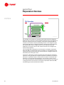
If not enough liquid refrigerant enters the evaporator, it vaporizes too quickly
(A). As a result, the remaining coil tubes fill with vapor, producing very little
refrigeration effect.
TRG-TRC005-EN
27
period four
Expansion Devices
notes
TXV Control
liquid
refrigerant
liquid/vapor
mixture
Figure 42
On the other hand, if too much liquid refrigerant enters the evaporator, not all of
it will be vaporized. As a result, some liquid refrigerant gets into the
compressor suction line. Since the compressor is designed to compress vapor
and not liquid, liquid refrigerant can cause excess wear and damage to the
compressor.
Superheat
85 psia,
psia, 41ºF
[0.59 MPa,
MPa, 5ºC]
TXV
liquid
refrigerant
290 psia,
psia, 109ºF
[2 MPa,
MPa, 42.8ºC]
A
superheated
vapor
Figure 43
The TXV meters refrigerant by measuring the condition of the refrigerant vapor
leaving the evaporator. Superheat is the additional heat absorbed by the
refrigerant in the evaporator after it has completely vaporized. It provides a
safety factor by preventing liquid refrigerant from entering the compressor.
In the example above, subcooled liquid refrigerant enters the TXV at a
condensing pressure of 290 psia [2 MPa] and a temperature of 109°F [42.8°C].
(The refrigerant condensed at 124.3°F [51.3°C] and was subcooled to 109°F
[42.8°C].) Passing through the TXV causes a large pressure drop, reducing the
refrigerant pressure to that of the evaporator. This pressure drop causes a small
28
TRG-TRC005-EN
period four
Expansion Devices
notes
portion of the liquid to boil off, or flash, and has the effect of cooling the
remaining liquid refrigerant to the desired evaporator temperature. The
resulting pressure of the refrigerant is 85 psia [0.59 MPa], which corresponds to
41°F [5°C].
Inside the evaporator tubes, as heat is transferred to the liquid refrigerant it
boils until only vapor remains (A). From this point, the vapor continues to
absorb heat as it passes through the final lengths of coil tubing, superheating
the vapor.
Superheat
85 psia,
psia, 41ºF
[0.59 MPa,
MPa, 5ºC]
79 psia
49ºF
[0.54 MPa]
MPa]
TXV
290 psia,
psia, 109ºF
[2 MPa,
MPa, 42.8ºC]
[9.4ºC]
Figure 44
Continuing with this example, the refrigerant enters the evaporator coil at
85 psia [0.59 MPa] and 41°F [5°C]. Assuming that the pressure drop through the
coil tubes is 6 psi [0.04 MPa], the refrigerant vapor leaves the coil at 79 psia
[0.54 MPa]. The temperature gauge at the outlet of the evaporator coil indicates
that the superheated refrigerant vapor leaves at 49°F [9.4°C].
A table of refrigerant properties, for Refrigerant-22 in this example, would show
that the 79 psia [0.54 MPa] pressure corresponds to a 37°F [2.8°C] evaporating
temperature. The 12°F [6.7°C] temperature difference between this evaporating
temperature and the temperature measured at the outlet of the evaporator is
the amount of additional heat, or superheat, absorbed by the refrigerant vapor
in the final lengths of coil tubing. Notice that superheating the refrigerant vapor
changed only its temperature—not its pressure.
These same properties—the evaporator pressure and the final refrigerant vapor
temperature—are measured and used by the thermostatic expansion valve to
control the quantity of liquid refrigerant entering the evaporator.
TRG-TRC005-EN
29
period four
Expansion Devices
notes
TXV Operation
evaporator
diaphragm
spring
remote
bulb
suction
line
external equalizer
distributor
Figure 45
In a typical TXV application, the outlet of the valve is connected to the
distributor. A remote bulb is attached to the suction line, where it senses the
refrigerant vapor temperature leaving the evaporator. This bulb is charged with
refrigerant and as heat is transferred from the suction line to the bulb, the
refrigerant inside the bulb vaporizes. The resulting refrigerant vapor pressure is
transmitted through a tube to the space above a diaphragm in the TXV.
The pressure of the refrigerant vapor leaving the evaporator is transmitted to
the space beneath the diaphragm through an external equalizing line that is
tapped into the suction line downstream of the bulb.
Finally, the valve contains an adjustable spring that applies a force to the lower
side of the diaphragm.
30
TRG-TRC005-EN
period four
Expansion Devices
notes
TXV Operation
valve diaphragm
97 psia
[0.67 MPa]
MPa]
49ºF
spring
[94ºC]
79 psia
[0.54 MPa]
MPa]
suction
line
79 psia 18 psi
[0.54 MPa]
MPa] [0.13 MPa]
MPa]
valve pin
Figure 46
Using the conditions from the previous example, the 49°F [9.4°C] refrigerant
vapor leaving the evaporator boils the refrigerant in the bulb, generating
97 psia [0.67 MPa] of pressure within the remote bulb. This pressure is
transmitted to the top side of the valve diaphragm, creating a force that pushes
down on the diaphragm.
The 79 psia [0.54 MPa] evaporating pressure, on the other hand, is transmitted
to the bottom side of the valve diaphragm, producing an opposing force.
Since the difference between the evaporator pressure and the pressure within
the remote bulb is due to superheat, the tension of the spring is adjusted to
provide the difference in order to balance the forces and produce the desired
amount of superheat. In this example, the spring tension is adjusted to produce
an 18 psi [0.13 MPa] pressure difference, which corresponds to 12°F [6.7°C] of
superheat.
Any variation in evaporator pressure causes these forces to vary from this
equilibrium and move the pin up or down, thus closing or opening the valve.
Closing the valve reduces the flow of refrigerant to the evaporator, while
opening the valve increases the flow. In other words, with this valve spring
adjustment, the refrigerant vapor must absorb 12°F [6.7°C] of superheat before
the forces that open and close the valve come into equilibrium, stabilizing the
refrigerant flow rate to the evaporator.
TRG-TRC005-EN
31
period four
Expansion Devices
notes
TXV Operation
external equalizer
TXV
remote
bulb
B
A
C
Figure 47
For example, assume that an increasing system load causes the refrigerant
within the coil to vaporize at a faster rate than desired. This moves the point at
which the refrigerant becomes completely vaporized from A toward B. This
increase in coil surface used for superheating results in the refrigerant vapor
leaving the evaporator at a higher temperature. Sensing the rising superheat,
the remote bulb transmits a higher pressure to the top side of the TXV
diaphragm, causing the valve to open further and allow more refrigerant to
flow into the evaporator.
This increased flow of refrigerant moves the point of complete vaporization
back toward A, until the desired superheat condition is reestablished and the
opening and closing forces within the valve equalize at a refrigerant flow rate
that balances the new system load.
Conversely, a decreasing system load slows the rate at which the refrigerant
vaporizes, moving the point of complete vaporization toward C. The resulting
reduction in superheat creates a lower pressure inside the remote bulb and,
therefore, on the top side of the diaphragm. This causes the valve to close
more, reducing the flow of liquid refrigerant into the evaporator. This reduction
in refrigerant flow moves the point of complete vaporization back toward A,
reestablishing the desired superheat condition.
32
TRG-TRC005-EN
period four
Expansion Devices
notes
Superheat Setting
I
Too little superheat:
K Risk
I
of damage to compressor by liquid refrigerant
Too much superheat:
K Reduction
K Potential
K Risk
of system efficiency
of coil frosting
of compressor damage due to overheating
Figure 48
A typical recommended superheat setting is from 8 to 12°F [4.4 to 6.7°C].
Too little superheat is risky because it presents a danger of allowing refrigerant
to leave the evaporator in the liquid state. As mentioned earlier, the compressor
is designed to compress vapor, not liquid. Liquid refrigerant can cause damage
to the compressor.
Too much superheat dedicates too much of the tube surface to the production
of superheat, reducing system efficiency. In extreme cases, it can lead to coil
frosting; it may also cause the compressor to overheat, possibly shortening its
service life.
TRG-TRC005-EN
33
period five
Accessories
notes
Refrigeration
System Components
period five
Accessories
Figure 49
This period discusses several accessories used in comfort-cooling refrigeration
systems.
Solenoid Valve
Figure 50
Solenoid Valve
A solenoid valve is used to stop the flow of refrigerant within the system.
These valves are magnetically operated, and an electric winding controls the
opening and closing of the valve. The valve is typically a normally-closed type
of valve so that it is closed when it is deenergized.
34
TRG-TRC005-EN
period five
Accessories
notes
Solenoid Valve
expansion
valve
finned-tube
evaporator
solenoid
valves
Figure 51
One common use of a solenoid valve is to control the flow of liquid refrigerant
to multiple sections of the evaporator. In this application, a valve is installed in
the liquid line, upstream of the expansion valve for each individually controlled
section of the evaporator coil.
Using the example of a face-split evaporator coil, at lower loads a solenoid
valve may be used to shut off the flow of liquid refrigerant to the top section of
the coil. A portion of the air passes through the active lower section and is
cooled, while the rest of the air passes through the inactive top section and
remains unconditioned. The two airstreams mix downstream of the coil. At
higher loads, both sections of the coil are activated.
Solenoid Valve
discharge
line
liquid line
condenser
expansion
valve
solenoid
valve
compressor
evaporator
suction
line
Figure 52
Another common use of a solenoid valve is to enable system pump-down and
prevent the refrigerant from migrating through the system when the
compressor is shut off. In this application, a single solenoid valve is installed in
the liquid line, upstream of all expansion valves.
TRG-TRC005-EN
35
period five
Accessories
notes
When the compressor is shut off, the evaporator contains a large quantity of
liquid refrigerant. This can present a problem if some of the refrigerant drains
into the suction line and slugs the compressor when it starts up again. To
prevent this from occurring, many systems pump the refrigerant out of the
evaporator and suction line before shutting the compressor off. This is called a
pump-down cycle. Instead of shutting the compressor off right away, the
solenoid valve is closed to stop the flow of liquid refrigerant into the
evaporator, and the compressor is allowed to run for a short period of time. The
compressor pumps the refrigerant from the low-pressure side of the system
(evaporator and suction line) to the high-pressure side of the system (discharge
line, condenser, and liquid line.)
As the low-pressure side of the system is pumped free of refrigerant, the
pressure in that part of the system drops. To end the pump-down cycle, a
pressure sensor is used to shut the compressor off when this pressure reaches
a predetermined set point. Prior to starting the compressor again, the solenoid
valve is opened, allowing the pressure on the low-pressure side of the system
to increase again.
The solenoid valve should be installed as close to the expansion valve as
possible. This will minimize the pump-down time and allow the liquid line to be
used for storing refrigerant when the system is off.
Liquid-Line Filter Drier
liquid line
liquid-line
filter drier
expansion
valve
solenoid
valve
evaporator
Figure 53
Liquid-Line Filter Drier
The next accessory to be discussed, the liquid-line filter drier, is installed
upstream of the solenoid valve and the expansion valve. It prevents moisture
(water) and foreign matter, introduced during the installation process, from
entering the expansion valve and the solenoid valve. Realize, however, that
there is no substitute for cleanliness during system installation.
Moisture and foreign matter can cause problems in any refrigeration system.
When water is mixed with refrigerant and oil, and heat is added by the
compressor, acids are formed that can damage the valves or compressor.
Additionally, certain foreign materials such as copper and brass particles can
36
TRG-TRC005-EN
period five
Accessories
notes
act as a catalyst in chemical reactions that result in the formation of acids.
These acids can corrode system components and cause the oil to sludge.
The filter drier should be installed close to the solenoid valve to provide the
most protection for the solenoid and expansion valves.
Liquid-Line Filter Drier
replaceable
core type
core
sealed type
Figure 54
A typical liquid-line filter drier includes a molded, porous core. The core has a
high affinity for moisture and removes foreign matter from the refrigerant.
The two common types of filter driers are replaceable core and sealed. The
replaceable core type allows the core to be easily replaced. The sealed type is
completely closed, reducing the chances of refrigerant leaks.
Ball-type shutoff valves are typically installed just upstream and downstream to
allow the filter drier to be isolated and the core (or unit) replaced.
TRG-TRC005-EN
37
period five
Accessories
notes
Moisture-Indicating Sight Glass
liquid line
sight
glass
expansion
valve
Figure 55
Moisture-Indicating Sight Glass
A moisture-indicating sight glass is installed in the liquid line, upstream of
the expansion valve, and permits the operator to observe the condition of the
refrigerant prior to entering the expansion valve. The value of the sight glass is
in its moisture indication ability—the sight glass should not be used to
determine system refrigerant charge or subcooling. Actual temperature and
pressure measurements are required to determine proper charge and
subcooling.
With the sight glass installed directly ahead of the expansion valve, it can also
be used to detect the presence of bubbles in the liquid line. This would indicate
that some of the liquid refrigerant has flashed into vapor upstream of the
expansion valve. Since the expansion valve is designed to control the flow of
liquid refrigerant only, the presence of refrigerant vapor results in a reduction in
the quantity of liquid refrigerant being fed to the evaporator. There are many
potential causes of liquid refrigerant flashing. The sight glass can alert the
operator to the condition.
38
TRG-TRC005-EN
period five
Accessories
notes
Suction Line Filter
suction
line filter
compressor
suction
line
Figure 56
Suction Line Filter
Similar to the liquid-line filter drier, the suction line filter performs the task of
removing foreign matter from the refrigeration system. It is installed in the
suction line, just upstream of the compressor.
The suction filter contains filter media to remove copper filings, flux, dirt, and
other foreign matter that may have been introduced during the installation
process or as the result of a compressor failure. It protects the compressor parts
from the abrasive action that could result if these materials enter the
compressor. Dirt can obstruct oil passages, robbing the compressor bearings of
lubrication.
Suction Line Filter
replaceable
core type
sealed type
Figure 57
Similar to the liquid-line filter drier, the two common types of suction line filters
are replaceable core and sealed. The replaceable core type allows the core to be
easily replaced. The sealed type is completely closed, reducing the chances of
refrigerant leaks.
TRG-TRC005-EN
39
period five
Accessories
notes
Replaceable core suction filters are commonly installed after a compressor
failure has occurred. The core is replaced after the foreign matter or acid has
been removed from the system.
Additionally, suction filters should be installed in all field-assembled systems.
Hot Gas Muffler
discharge
line
reciprocating
compressor
hot gas
muffler
shell
perforated tube
Figure 58
Hot Gas Muffler
The purpose of the hot gas muffler is to smooth out the pulsations associated
with the refrigerant vapor being discharged from a reciprocating compressor,
reducing noise and vibration.
The pressure of the refrigerant vapor leaving a reciprocating compressor
fluctuates rapidly because of the manner in which it is compressed by the
reciprocating pistons. The muffler contains a perforated tube inside a shell. The
pressure peaks cause some of the refrigerant vapor to pass from the perforated
tube into the muffler shell. This shell is divided into chambers that allow it to
absorb these peaks. In essence, the muffler shaves off the peaks of these
pulsations and fills in the valleys, reducing the pulsating characteristic in the
discharge line.
When used, the hot gas muffler should be located in the discharge line, as close
to the reciprocating compressor discharge as possible. This minimizes the
sound emission from the unmuffled section of discharge line.
40
TRG-TRC005-EN
period five
Accessories
notes
Shutoff Valve
shutoff
valve
shutoff
valve
liquid line
condenser
liquid-line
filter drier
evaporator
shutoff
valves
compressor
Figure 59
Shutoff Valve
Shutoff valves are used to isolate one part of the refrigeration system from
the rest. Additionally, they can be used to trap the refrigerant charge in one
component of the system, the condenser for example, to permit service or
repair to another part of the system.
Common uses of shutoff valves include:
TRG-TRC005-EN
■
Isolating the liquid-line filter drier and suction filter to allow easier core (or
unit) replacement
■
Isolating the compressor from the rest of the system to allow for repair or
replacement
■
Isolating the charge within the condenser or a receiver to allow access to the
rest of the system
41
period five
Accessories
notes
Access Port
liquid line
access port
condenser
evaporator
compressor
suction line
access ports
Figure 60
Access Port
An access port is used to add refrigerant to the system or for measurement.
An access port is typically installed in the liquid line in a convenient location
and is used to charge the system with liquid refrigerant. It is also used to
measure subcooling.
The suction line typically includes two access ports. One is installed near the
compressor and is used to measure suction pressure. The other is located near
the external equalizer-line connection for the expansion valve, and is used to
measure superheat when checking or adjusting the expansion valve setting.
42
TRG-TRC005-EN
period six
Review
notes
Refrigeration
System Components
period six
Review
Figure 61
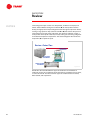
We will now review the main concepts that were covered in this clinic about the
components in a vapor-compression refrigeration system.
Review—Period One
pressure
D
condenser
C
expansion
device
A
compressor
evaporator
enthalpy
B
Figure 62
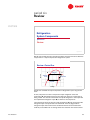
Period One reviewed the vapor-compression refrigeration cycle using the P-h
chart.
A cool, low-pressure mixture of liquid and vapor refrigerant enters the
evaporator (A) and absorbs heat from the relatively warm air or water that is
being cooled. This transfer of heat boils the liquid refrigerant in the evaporator
and superheated refrigerant vapor (B) is drawn to the compressor.
The compressor raises the pressure and temperature (C) high enough that the
refrigerant vapor can reject heat to another fluid. This hot, high-pressure
refrigerant vapor then travels to the condenser where heat is transferred to
relatively cool ambient air or cooling water. This reduction in the heat content
TRG-TRC005-EN
43
period six
Review
notes
of the refrigerant vapor causes it to desuperheat, condense into liquid, and
further subcool before leaving the condenser (D) for the expansion device.
Finally, the high-pressure liquid refrigerant flows through the expansion device,
causing a large pressure drop (the line from D to A) that reduces the pressure
of the refrigerant to that of the evaporator. This pressure reduction causes a
small portion of the liquid to boil off, or flash, cooling the remaining refrigerant
to the desired evaporator temperature. The cooled refrigerant then enters the
evaporator (A) to repeat the cycle.
Review—Period Two
evaporative
condenser
air-cooled
condenser
water-cooled
condenser
Figure 63
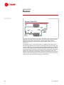
Period Two discussed the different types of condensers and methods of
condenser control. The condenser rejects heat from the refrigerant to air, water,
or some other fluid. The three common types of condensers are air-cooled,
water-cooled, and evaporative.
44
TRG-TRC005-EN
period six
Review
notes
Review—Period Three
finned-tube
evaporator
shell-and-tube
evaporator
Figure 64
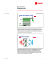
Period Three presented the different types of evaporators and methods of
evaporator control. The evaporator transfers heat from air, water, or some other
fluid to the cool liquid refrigerant. The two common types of evaporators are
finned-tube and shell-and-tube.
Review—Period Four
evaporator
distributor
TXV
remote
bulb
external equalizer
Figure 65
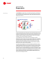
Period Four reviewed the operation of the expansion device, specifically the
thermostatic expansion valve. The expansion device is used to maintain the
pressure difference between the high-pressure (condenser) and low-pressure
(evaporator) sides of the system established by the compressor.
In addition, the thermostatic expansion valve (TXV) controls the quantity of
liquid refrigerant entering the evaporator. It ensures that the refrigerant will be
completely vaporized within the evaporator and maintains the proper amount
of superheat in the system.
TRG-TRC005-EN
45
period six
Review
notes
Review—Period Five
shutoff
valve
condenser
solenoid
valve
TXV
access
port
suction
line filter
compressor
liquid-line
filter drier
sight
glass
evaporator
Figure 66
Period Five discussed several accessories commonly used in comfort-cooling
applications, including: solenoid valve, liquid-line filter drier, moistureindicating sight glass, suction line filter, hot gas muffler, shutoff valve, and
access port.
The solenoid valve is used to stop the flow of refrigerant within the system. A
liquid-line filter drier prevents moisture and foreign matter from damaging the
valves or compressor. The moisture-indicating sight glass permits the operator
to observe the condition of the refrigerant within the liquid line before it enters
the expansion device. A suction line filter protects the compressor from foreign
matter in the suction line. The hot gas muffler is used to reduce noise and
vibration associated with reciprocating compressors. Shutoff valves are used to
isolate one part of the refrigeration system, and access ports allow a technician
to gain access to the system for charging or measurement.
46
TRG-TRC005-EN
period six
Review
notes
Figure 67
For more information, refer to the following references:
■
Trane Air Conditioning Manual
■
Trane Reciprocating Refrigeration Manual
■
“The DX Refrigerant Cooling Coil Conundrum” (Trane Engineers Newsletter,
1988—volume 17, number 1)
■
ASHRAE Handbook – Fundamentals
■
ASHRAE Handbook – Refrigeration
■
ASHRAE Handbook – Systems and Equipment
Visit the ASHRAE Bookstore at www.ashrae.org.
For more information on additional educational materials available from Trane,
contact your local Trane office (request a copy of the Educational Materials
catalog – Trane order number EM-ADV1) or visit our online bookstore at
www.trane.com/bookstore/.
TRG-TRC005-EN
47
Quiz
Questions for Period 1
pressure
G
D
E
F
H
B
A
C
enthalpy
Figure 68
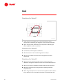
1 Using the pressure–enthalpy chart in Figure 68, which two points
correspond to superheating the refrigerant vapor inside the evaporator?
2 Again using Figure 68, which two points correspond to subcooling the
liquid refrigerant inside the condenser?
Questions for Period 2
3 List the three common types of condensers.
4 What two factors cause the condensing pressure to drop?
5 What are two methods of control that can be applied to air-cooled
condensers?
Questions for Period 3
6 What is the name of the device used to ensure uniform refrigerant
distribution through the multiple-coil circuits of a finned-tube evaporator?
7 What is the purpose of the baffles inside the shell-and-tube evaporator?
8 What are the three common arrangements for splitting finned-tube
evaporator coils?
9 When using a face-split coil in a constant-volume application, which section
(top or bottom) of the coil should be activated first and deactivated last?
48
TRG-TRC005-EN
Quiz
Questions for Period 4
10 What are the two primary purposes of a thermostatic expansion valve?
11 What are the risks of too much superheat in the system?
Questions for Period 5
12 During a pump-down cycle, the compressor pumps the refrigerant from the
_____ (low or high)-pressure side of the system to the _____ (low or high)pressure side.
13 Is the moisture-indicating sight glass installed upstream or downstream of
the expansion valve?
TRG-TRC005-EN
49
Answers
1 B to C
2 F to G
3 Air-cooled, evaporative, and water-cooled
4 A decrease in system load and a reduction in the outdoor air temperature
5 Varying the airflow through the condenser coil or flooding the condenser
coil with liquid refrigerant
6 A distributor
7 To direct the water in a rising and falling flow path over the tubes that carry
the refrigerant; resulting in turbulence that improves heat transfer
8 Face-split, intertwined, and row-split
9 Bottom section
10 The thermostatic expansion valve a) maintains the pressure difference
between the high-pressure and low-pressure sides of the system, and b)
maintains the proper amount of superheat in the system by metering the
quantity of liquid refrigerant entering the evaporator, ensuring it will be
completely vaporized within the evaporator.
11 Too much superheat dedicates too much of the tube surface to the
production of superheat, reducing system efficiency. In extreme cases, it
can lead to coil frosting and overheating of the compressor, compromising
its longevity.
12 Low-pressure side to the high-pressure side
13 Upstream of the expansion valve
50
TRG-TRC005-EN
Glossary
access port A device that allows a technician to gain access to the
refrigeration system for charging or measurement.
air-cooled condenser A type of condenser where refrigerant flows through the
tubes and rejects heat to air that is drawn across the tubes.
ASHRAE American Society of Heating, Refrigerating and Air-Conditioning
Engineers
capillary tube A type of expansion device that uses a long, narrow tube to
reduce the pressure and temperature of the refrigerant.
centrifugal fan air-cooled condenser A type of air-cooled condenser that uses
a centrifugal fan instead of a propeller fan, allowing it to overcome the larger
static pressures associated with ductwork.
compressor The mechanical device in the refrigeration system used to
increase the pressure and temperature of the refrigerant vapor.
condenser The component of the refrigeration system where refrigerant
vapor is converted to liquid as it rejects heat to water or air.
cooling tower A device used to reject the heat from a water-cooled condenser
by spraying the condensing water over the fill while drawing outdoor air
upward through the fill.
distributor A device used to ensure uniform refrigerant distribution through
the multiple-coil circuits of a finned-tube evaporator.
electronic expansion valve A type of expansion device that uses an
electronically-actuated valve to sense and control the flow rate of liquid
refrigerant to the evaporator.
enthalpy The property of a refrigerant indicating its heat content, both
sensible and latent, per pound [kg] of refrigerant.
evaporative condenser A type of condenser where refrigerant flows through
the tubes and rejects heat to air. The air is drawn across the tubes, which are
wetted on the outside by circulating water.
evaporator The component of the refrigeration system where cool liquid
refrigerant absorbs heat from air, water, or some other fluid, causing the
refrigerant to boil.
expansion device The component of the refrigeration system used to reduce
the pressure and temperature of the refrigerant.
expansion valve The type of expansion device that maintains the pressure
difference between the high-pressure and low-pressure sides of the system. It
also maintains the proper amount of superheat in the system by metering the
quantity of liquid refrigerant entering the evaporator, ensuring that the
refrigerant will be completely vaporized within the evaporator
TRG-TRC005-EN
51
Glossary
face-split A type of finned-tube evaporator arrangement that splits the coil
into parallel air paths.
fill
The heat transfer surface inside a cooling tower.
finned-tube evaporator A type of evaporator where refrigerant flows through
the tubes and air blows across the tubes and fins.
flash The process of liquid refrigerant being vaporized by a sudden reduction
of pressure.
hot gas muffler A device installed at the discharge of the compressor to
reduce noise and vibration associated with reciprocating compressors.
intertwined A type of finned-tube evaporator arrangement that splits the coil
by alternating the tubes fed in each row between two distributors.
liquid-line filter drier A device installed in the liquid line to remove moisture
(water) and foreign matter, introduced during the installation process, from the
refrigeration system.
moisture-indicating sight glass See sight glass, moisture indicating.
orifice plate A type of expansion device that uses a fixed plate with holes
drilled in it to reduce the pressure and temperature of the refrigerant.
pressure–enthalpy chart A graphical representation of the saturated
properties of a refrigerant, plotting refrigerant pressure versus enthalpy.
pump-down cycle A control sequence used in a refrigeration system to pump
the refrigerant from the low-pressure side of the system to the high-pressure
side of the system.
refrigeration effect The amount of heat that each pound [kg] of liquid
refrigerant will absorb when it evaporates.
row-split A type of finned-tube evaporator arrangement that splits the coil by
placing the independently-controlled coil sections in series in the airstream.
shell-and-tube evaporator A type of evaporator where refrigerant flows
through the tubes and water fills the surrounding shell.
shutoff valve
the rest.
Devices used to isolate one part of the refrigeration system from
sight glass, moisture-indicating A device installed in the liquid line, upstream
of the expansion valve, used to detect moisture in the system and determine if
the liquid refrigerant has flashed into vapor before entering the expansion
valve.
solenoid valve A device used to stop the flow of refrigerant within the
refrigeration system.
52
TRG-TRC005-EN
Glossary
subcooler The lower portion of the condenser that further cools the saturated
liquid refrigerant.
suction header A section of pipe used to collect the refrigerant vapor when it
leaves the tubes of a finned-tube evaporator coil.
suction line filter A device installed in the suction line to remove foreign
matter from the refrigeration system.
superheat The amount of heat added to the refrigerant vapor after it has
completely vaporized within the evaporator.
thermostatic expansion valve A type of expansion device that uses a
thermally-actuated valve to sense and control the flow rate of liquid refrigerant
to the evaporator.
water-cooled condenser A type of condenser where water flows through the
tubes and absorbs heat from the refrigerant that fills the surrounding shell.
TRG-TRC005-EN
53
Literature Order Number
The Trane Company
Worldwide Applied Systems Group
3600 Pammel Creek Road
La Crosse, WI 54601-7599
www.trane.com
An American Standard Company
TRG-TRC005-EN
File Number
E/AV-FND-TRG-TRC005-1199-EN
Supersedes
2803-3-784 and 2803-5-1284
Stocking Location
Inland-La Crosse
Since The Trane Company has a policy of continuous product improvement, it reserves the right to change
design and specifications without notice.