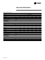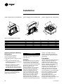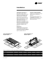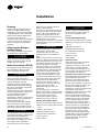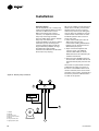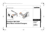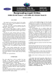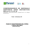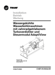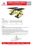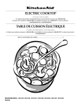
1
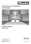
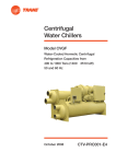
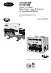
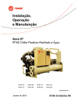
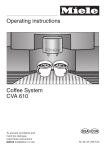
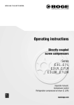
Installation Operation Maintenance RTUB 207-224 - Liquid chillers with helical rotary compressors RTCA 108-216 - Remote air-cooled condenser RLC-SVX03A-E4 Foreword These installation, operation and maintenance instructions are given as a guide to good practice in the installation, putting into service, operation, and maintenance by the user of Trane RTUB and RTCA units. They do not contain full service procedures necessary for the continued successful operation of this equipment; The services of a qualified technician should be employed through the medium of a maintenance contract with a reputable service company. Warranty Warranty is based on the general terms and conditions of Société Trane or Trane UK Ltd. The warranty is void if the equipment is repaired or modified without the written approval of Trane, if the operating limits are exceeded or if the control system or the electrical wiring is modified. Damage due to misuse, lack of maintenance or failure to comply with the manufacturer's instructions or recommendations is not covered by the warranty obligation. If the user does not conform to the rules of chapter "Maintenance", it may entail cancellation of warranty and liabilities by Trane. Units are shipped with the refrigerant operating or holding charge and should be examined with an electronic leak detector to determine the hermetic integrity of the unit. The refrigerant charge is not included in the standard Trane Warranty Cover. Cautions and warnings Cautions and warnings appear at appropriate places in this instruction manual. Your personal safety and the proper operation of this machine require that you follow them carefully. The constructor assumes no liability for installations or servicing performed by unqualified personnel. Refrigerant The refrigerant provided by Société Trane or Trane UK Ltd meets all the requirements of our units. When using recycled or reprocessed refrigerant, it is advisable to ensure its quality is equivalent to that of a new refrigerant. For this, it is necessary to have a precise analysis made by a specialized laboratory. If this condition is not respected, the Société Trane UK Ltd warranty could be cancelled. Reception of the unit On arrival, inspect the unit before signing the delivery note. Specify any damage on the delivery note, and send a registered letter of protest to the last carrier of the goods within 72 hours of delivery. Notify the local Trane Sales Office at the same time. The unit should be totally inspected within 7 days of delivery. If any concealed damage is discover, send a registered letter of protest to the carrier within 7 days of delivery and notify the local Trane Office. ©American Standard Inc. 2002 RLC-SVX03A-E4 Contents Foreword 2 Warranty 2 Reception of unit 2 Cautions and warnings 2 Refrigerant 2 General information Unit Inspection 5 Inspection Checklist 5 Loose Parts Inventory 6 Description of the Unit 6 General Data RTUB 7 General Data RTCA 8 Installation RLC-SVX03A-E4 Installation Responsibilities 9 Storage 9 Special Lifting and Moving Instructions 10 Isolation 10 Foundation 10 Clearances 11 Drainage 12 Releasing the Nitrogen Holding Charge 12 Water Connections (RTUB) 12 Flow Switch Installation 13 Water Pressure Gauges 13 Refrigeration Safety Valves 14 Water Pressure Relief Valves 14 Installing and Connecting Temperature Sensors 14 Connecting RTUB with the Remote Air-cooled Condenser 15 3 Contents Operation Pre-start Checkout 21 Unit Voltage Power Supply 21 Unit Voltage Imbalance 21 Unit Voltage Phasing 21 Water System Flow Rates 22 Water System Pressure Drop 22 Daily Unit Start-up Procedure 22 Seasonal Unit Start-up Procedure 23 Temporary Shutdown and Restart 23 Extended Shutdown Procedure 23 System Restart after Extended Shutdown 23 Maintenance 4 Periodic Maintenance 25 Refrigerant and Oil Charge Management 27 R134a Field-charging Procedure 28 Charge Isolation on the High or Low Side of the System 28 Filter Replacement Procedure 29 Lubrication System 29 Oil Charging Procedure 29 Safety Recommendations 32 Maintenance Contract 32 Training 32 CG-PRC010-E4 General information This manual describes installation, operation, and maintenance of RTUB and RTCA units. A separate manual is available for the use and maintenance of the RTUB controls (UCM-CLD). Unit Inspection When the unit is delivered, verify that it is the correct unit and that it is property equipped. Compare the information that appears on the unit nameplate with the ordering and submittal information. A typical unit nameplate is shown in Figure 1. Inspect all exterior components for visible damage. Report any apparent damage or material shortage to the carrier and make a "unit damage" notation on the carrier's delivery receipt. Specify the extent and type of damage found and notify the appropriate Trane Sales Office. Do not proceed with installation of a damaged unit without sales office approval. Inspection Checklist To protect against loss due to damage incurred in transit, complete the following checklist upon receipt of the unit. • Inspect the individual pieces of the shipment before accepting the unit. Check for obvious damage to the unit or packing material. • Inspect the unit for concealed damage as soon as possible after delivery and before it is stored. Concealed damage must be reported within 15 days. If concealed damage is discovered, stop unpacking the shipment. Do not remove damaged material from the receiving location. Take photos of the damage, if possible. The owner must provide reasonable evidence that the damage did not occur after delivery. • Notify the carrier's terminal of the damage immediately, by phone and by mail. Request an immediate, joint inspection of the damage with the carrier and the consignee. RLC-SVX03A-E4 5 General information • Notify the Trane sales representative and arrange for repair. Do not repair the unit, however, until damage is inspected by the carrier's representative. Loose Parts Inventory Check all the accessories and loose parts that are shipped with the unit against the shipping list. Included in these items will be water vessel drain plugs, rigging and electrical diagrams, and service literature, which are placed inside the control panel and/or starter panel for shipment. been assembled and wired in the factory. The discharge piping is blocked at the oil separator outlet. Water connections - chilled water inlet and outlet - are blocked for transportation. Both RTUB and RTCA units are dried and vacuum-pumped in the factory, and contain a nitrogen holding charge when shipped. Description of the Unit The RTUB units are liquid chillers equipped with two helical rotary compressors and an evaporator designed to operate with remote RTCA air-cooled condensers or other manufacturers' remote condensers. The RTUB is shipped once it has Figure 1 - Typical Unit Nameplates RTUB RTCA é 6 RLC-SVX03A-E4 General information Table 1 - General data - RTUB Unit size Compressor Type/quantity Nominal size Evaporator Evaporator Model Water Storage Minimum Flow Maximum Flow Evaporator inlet diameter Evaporator outlet diameter Minimum Starting/ Operating Ambient Refrigerant Number of Independent Refrigerant Circuits Percent Minimum Load Refrigerant Charge Oil Charge Operating Weight Shipping Weight Unit size Compressor Type/Quantity Nominal size Evaporator Evaporator Model Water Storage Minimum Flow Maximum Flow Evaporator inlet diameter Evaporator outlet diameter Minimum Starting/ Operating Ambient Refrigerant Number of Independent Refrigerant Circuits Percent Minimum Load Refrigerant Charge Oil Charge Operating Weight Shipping Weight RLC-SVX03A-E4 (tons) (l) (l/s) (l/s) (inches) (inches) 207 208 35/35 40/40 EG 120 105 4.5 13.4 5 5 EG 120 105 4.5 13.4 5 5 210 (tons) (l) (l/s) (l/s) (inches) (inches) 212 214 60/60 70/70 EG 170 220 7.0 21.0 6 6 EG 170 220 7.0 21.0 6 6 EG 200 200 9.0 25.0 6 6 Helical rotary/2 50/50 60/50 EG 140 365 6.0 18.0 6 6 (°C) (%) (kg) (l) (kg) (kg) 211 5 R134a 2 17 26 12 2130 1860 26 12 2130 1860 40 14 2845 2570 40 14 2845 2570 40 14 2845 2570 40 16 3250 2975 216 217 218 220 222 224 70/85 85/85 Helical rotary/2 100/85 100/100 120/100 120/120 EG 200 200 9.0 25.0 6 6 EG 200 200 9.0 25.0 6 6 EG 250 415 11.0 33.0 6 6 EG 250 415 11.0 33.0 6 6 EG 340 560 14.0 43.0 6 6 EG 340 560 14.0 43.0 6 6 46 16 4050 3575 50 19 4480 3855 50 22 4550 3925 (°C) 5 R134a 2 (%) (kg) (l) (kg) (kg) 40 16 3250 2975 40 16 3250 2975 17 46 16 3880 3405 7 General information Table 2 - General data - RTCA Unit size Condenser Condenser type Fin spacing Frontal surface area Airflow Standard unit Low noise unit Condenser fans Number of fans Fan speed Standard unit Low noise unit Nominal fan power Standard unit Low noise unit Current fan amps Standard unit Low noise unit Minimum Starting/ Operating Ambient (1) Refrigerant Number of Independent Refrigerant Circuits Refrigerant Charge Operating Weight (2) Shipping Weight (2) Hot gas connection Liquid connection 108 109 (fins/ft) (m²) 168 5.7 168 6.9 (m3/h) (m3/h) 42500 34500 50400 40900 69300 56300 4 4 6 113 115 116 168 11.7 144 13.7 77200 62700 84700 68800 98500 80000 8 8 12 Aluminium fins/copper tubes 144 168 6.9 11.3 (rpm) (rpm) 690 560 (kW) (kW) 0.85 0.54 (A) (A) 2.4 1.2 (°C) 7 Standard units/-18 Low ambient units R134a (kg) (kg) (kg) (inches) (inches) Unit size Condenser Condenser type Fin spacing (fins/ft) Frontal surface area (m²) Airflow Standard unit (m3/h) Low noise unit (m3/h) Condenser fans Number of fans Fan speed Standard unit (rpm) Low noise unit (rpm) Nominal fan power Standard unit (kW) Low noise unit (kW) Current fan amps Standard unit Low noise unit Minimum Starting/ Operating Ambient (1) (°C) Refrigerant Number of Independent Refrigerant Circuits Refrigerant Charge (kg) Operating Weight (2) (kg) Shipping Weight (2) (kg) Hot gas connection (inches) Liquid connection (inches) (1) Based on a 2.2 m/s wind across the condenser (2) With aluminium fins 8 111 1 22 810 1020 1 5/8 1 1/8 1 26 890 1100 1 5/8 1 1/8 1 36 1090 1300 1 5/8 1 1/8 1 44 1535 1870 1 5/8 1 1/8 1 52 1770 2170 1 5/8 1 1/8 1 72 2050 2450 1 5/8 1 1/8 208 209 211 213 215 216 168 5.7 168 6.9 168 11.7 144 13.7 42500 34500 50400 40900 69300 56300 77200 62700 84700 68800 98500 80000 2x2 2x2 2x3 2x4 2x4 2x6 2 2 x 26 1770 2170 1 5/8 1 1/8 2 2 x 36 2050 2450 1 5/8 1 1/8 Aluminium fins/copper tubes 144 168 6.9 11.3 690 560 0.85 0.54 2.4 1.2 7 Standard units/-18 Low ambient units R134a 2 2 x 11 810 1020 1 5/8 1 1/8 2 2 x 13 890 1100 1 5/8 1 1/8 2 2 x 18 1090 1300 1 5/8 1 1/8 2 2 x 22 1535 1870 1 5/8 1 1/8 RLC-SVX03A-E4 Installation Installation responsibilities Generally, the contractor must do the following when installing an RTUB/RTCA unit. • Install the units on a flat foundation, level (within 1/4" [6 mm] across the length of the unit), and strong enough to support unit loading. • Install the units per the instructions contained in the Installation section of this manual. • Install any optional sensors and make electrical connections at the UCM-CLD. • Where specified for the RTUB, provide and install valves in the water piping upstream and downstream of the evaporator water connections, to isolate the evaporator for maintenance and to balance and trim the system. • Furnish and install a flow switch and/or auxiliary contacts to prove chilled-water flow. • Install heat tape and insulate the chilled-water lines and any other portions of the system, as required, to prevent sweating under normal operating conditions or freezing during low-ambient temperature conditions. • Start the unit under the supervision of a qualified service technician. Storage If the chiller is stored for a long period of time prior to installation, the following precautionary measures must be taken: • Store the unit in a safe place sheltered from bad weather • At least every three months (quarterly), check the pressure in the refrigerant circuits to verify that the nitrogen holding charge is intact. If it is not, contact a qualified service organization and the appropriate Trane sales office. • Close the discharge and liquid-line isolation valves. • Furnish and install pressure gauges in the inlet and outlet piping of the evaporator (for RTUB). • Furnish and install a drain valve to the bottom of the evaporator water box (for RTUB). • Supply and install a vent cock to the top of the evaporator water box (for RTUB). • Furnish and install strainers ahead of all pumps and automatic modulating valves. • Furnish and install check valves on the discharge lines (between oil separators and condenser) in order to avoid any refrigerant migration leading to catastrophic damages to evaporator and/or compressor (due to freeze-up or liquid slugging). • Interconnect the RTUB and the remote condenser. • Provide and install field wiring. RLC-SVX03A-E4 9 Installation Figure 2- Rigging the unit - RTUB 207-208 Figure 3- Rigging the unit - RTUB 210-224 Figure 4- Rigging the unit - RTCA 108-216 Table 3 - Sling Lengths (mm) for lifting RTUB unit size 207-208 210-211-212 214-216-217 218-220 222-224 RTCA unit size 108/109/111/208/209/211 113/115/115/213/215/216 Special Lifting and Moving Instructions A specific lifting method is recommended as follows: 1. Four lifting points are built into the unit. 2. Slings and spreader bar to be provided by rigger and attached to the four lifting points. 3. Minimum rated lifting capacity (vertical) of each sling and spreader bar shall be no less than the tabulated unit shipping weight. C AUTION This unit must be lifted with the utmost care. Avoid shock load by lifting slowly and evenly. 10 A B C D E 2200 2400 2500 2450 2450 3000 3000 3000 3050 3100 2600 2550 2550 2600 2650 2100 3150 3150 3150 3150 3650 3650 3650 3650 2240 2240 1700 2800 1700 2800 - - WARNING To prevent any damage, position the lifting bar so that the slings do not touch the unit. Isolation The most effective form of isolation is to locate the unit away from any sound-sensitive area. Structurally transmitted sound can be reduced by elastomeric vibration eliminators. Spring isolators are not recommended for units equipped with helical rotary compressors. Consult an acoustical engineer in critical sound applications. For maximum isolation effect, isolate water lines and electrical conduit. Wall sleeves and rubber- isolated piping hangers can be used to reduce the sound transmitted through water piping. To reduce the sound transmitted through electrical conduit, use flexible electrical conduit. State and local codes on sound emissions should always be considered. Foundation Provide rigid, non-warping mounting pads or a concrete foundation of sufficient strength and mass to support the unit's operating weight (that is, including completed piping, and full operating charges of refrigerant, oil, and water). After it is in place, the unit must be level within 1/4" [6 mm] over its length and width. Use shims if necessary. The manufacturer is not responsible for equipment problems resulting from an improperly designed or constructed foundation. Note for RTCA: The unit must be positioned so that the airflow through the condensation coils is not hindered by any obstacle. The RLC-SVX03A-E4 Installation condensation coils must be protected from side winds when their speed exceeds 16 km/h. Position the unit above the average height of snow observed in the region where it is installed. Never install temporary or permanent objects (tarp or roof) over the unit, because recycling of hot air would reduce the capacity of the condensation coils. Discharged air from the fans must not be obstructed. It is prohibited to install ducts for the fan discharge air (even short ones). This is because the fans supplied on standard units do not generate any additional static pressure. dimensions and recommended clearances. Unobstructed flow of condenser air is essential to maintain chiller capacity and operating efficiency. Note for RTCA: When determining unit placement, give careful consideration to ensuring a sufficient flow of air across the condenser heat-transfer surface. Clearances Provide enough space around the unit to allow the installation and maintenance personnel unrestricted access to all service points. Refer to Figure 5 and Table 4 for unit Figure 6: Unit Dimensions and Recommended Minimum Clearances - RTUB Figure 5: Unit Dimensions and Recommended Minimum Clearances - RTCA C D B B A A D C Table 4 - Unit Dimensions and Recommended Minimum Clearances (mm) RTCA 108/109/111/208/209/211 RTCA 113/213 RTCA 115/116/215/216 RTUB 207/208 RTUB 210/211/212/214/216/217 RTUB 218/220 RTUB 222/224 RLC-SVX03A-E4 Length 2870 4610 5450 2880 4150 4150 4150 Width 2285 2285 2285 890 890 890 890 Height 1630 1630 1630 1789 1832 1932 2041 A 1000 1000 1000 950 950 950 950 B 1000 1000 1000 800 800 800 800 C 1000 1000 1000 1800 2750 2750 2750 D 1000 1000 1000 500 500 500 500 11 Installation Drainage Provide a large-capacity drain for water vessel drain-down during shutdown or repair. The evaporator is provided with a drain connection. All local and national codes apply. The vent on the top of the evaporator water box is provided to prevent a vacuum, by allowing air into the evaporator for complete drainage. Releasing the Nitrogen Holding Charge The nitrogen holding charge can be released into the atmosphere. C AUTION When releasing nitrogen holding charge, ventilate the room. Avoid breathing in the nitrogen. Water Connections (RTUB) Thoroughly flush all water piping to the unit before making the final piping connections to the unit. C AUTION If using an acidic commercial flushing solution, construct a temporary bypass around the unit to prevent damage to internal components of the evaporator. To avoid possible equipment damage, do not use untreated or improperly treated system water. When making the water connections, use flange connectors. Insulate all piping to reduce temperature increases and to prevent condensation. Figure 7 shows all the piping systems for the evaporator and its components. The arrangement of the pipes and the other components varies slightly according to the positioning of the connections and the water source. C AUTION The chilled water connections to the evaporator are Victaulic connections. Do not attempt to weld these connections, because the heat generated from welding can cause microscopic and macroscopic fractures on the cast- iron water 12 boxes that can lead to premature failure of the water box. A vent line is located on the top part of the evaporator at the water return piping end. Install additional vent lines at the highest points in the piping to vent the air present in the chilled water circuit. Install manometers to monitor the pressure of chilled water entering and leaving the evaporator. C AUTION To prevent damage to chilled-water components, do not allow evaporator pressure (maximum working pressure) to exceed 10.5 bars. Provide shutoff valves in lines to the gauges, in order to isolate them from the system when they are not in use. Use rubber vibration eliminators to prevent vibration transmission through the water lines. If desired, install thermometers in the lines to monitor entering- and leaving-water temperatures. Install a balancing valve in the leaving-water line to control water flow balance. Install shutoff valves on both the enteringand leaving-water lines so that the evaporator can be isolated for service. A pipe strainer must be installed in the entering water line. Failure to do so can allow waterborne debris to enter the evaporator. "Piping components" include all devices and controls used to provide proper water system operation and unit operating safety. These components and their general locations are given in Figure 7. Entering Chilled-Water Piping • Air vents (to bleed air from system). • Water pressure gauges with shutoff valves. • Vibration eliminators. • Shutoff (isolation) valves. • Thermometers (if desired). • Clean out tees. • Pipe strainer. C AUTION Install a strainer in the evaporatorwater inlet piping. Failure to do so can result in evaporator tube damage. Leaving Chilled-Water Piping • Air vents (to bleed air from system). • Water pressure gauges with shutoff valves. • Vibration eliminators. • Shutoff (isolation) valves. • Thermometers (if desired). • Clean out tees. • Balancing valve. • Flow Switch Evaporator Drain A 3/4" drain connection is located under the outlet end of the evaporator water box. This may be connected to a suitable drain to permit evaporator drainage during unit servicing. A shutoff valve must be installed on the drain line. Evaporator Flow Switch (accessory) The chilled water flow is protected by the UCM-CLD without the assistance of a chilled water flow switch. The flow switch is optional, but if it is not installed, a signal must be sent to the chiller to indicate the water flow is established, for example the auxiliary contacts of the chilled water pump starter. If additional protection of the chilled water flow proves necessary, connect a flow switch installed on site, or a differential pressure switch to control the system's water flow. Connect the flow switch in series with the auxiliary contacts of the chilled water pump motor starter. A special connector is supplied with the unit, with the wiring diagrams. Some piping and control schemes, particularly those using a single water pump for both chilled- water and hot water, must be analyzed to determine how and/or if a flowsensing device will provide the desired operation. RLC-SVX03A-E4 Installation Follow the manufacturer's instructions for the installation procedures. Flow Switch Installation 1. Mount the switch upright, with a minimum of 5 pipe diameters of straight horizontal run on each side. Do not install close to elbows, orifices, or valves. Note: The arrow on the switch must point in the direction of flow. 2. To prevent switch fluttering, remove all air from the water system. Note: The UCM-CLD waits for six seconds after a “flow loss” diagnosis before stopping the unit. Contact a qualified service representative if nuisance machine shutdowns persist. 3. Adjust the switch to open when water flow falls below nominal. Evaporator data is given in Table 1. Flow-switch contacts are closed on proof of water flow. 4. Install a pipe strainer in the entering evaporator-water line to protect components from waterborne debris. Water Treatment C AUTION If calcium chloride is used for waste treatment, an applicable corrosion inhibitor must also be used. Failure to do so may result in damage to system components. Dirt, scale, products of corrosion, and other foreign material will adversely affect heat transfer between the water and system components. Foreign matter in the chilled-water system can also increase pressure drop and, consequently, reduce water flow. Proper water treatment must be determined locally, depending on the type of system and local water characteristics. Neither salt nor brackish water is recommended for use in Trane units. Use of either will lead to a shortened life to an indeterminable degree. The Trane Company encourages the employment of a reputable water treatment specialist, familiar with local water conditions, to assist in this determination and in the establishment of a proper watertreatment program. Water Pressure Gauges Install field-supplied pressure components as shown in Figure 7. Locate pressure gauges or taps in a straight run of pipe; avoid placement near elbows, and so forth. Be sure to install the gauges at the same elevation on each shell if the shells have opposite-end water connections. Note: After the unit is installed at a site, one vertical (or one diagonal) unit support can be permanently removed if it creates an obstruction for water piping. To read Figure 7 - Typical piping of the evaporator (RTUB) 1 Air vent 2 Balance valve 3 Flow switch 4 Thermometers 5 Expansion joints 6 Stop valves 7 Manometer 8 Evaporator 9 Filter 10 Drainage 7 3 8 2 6 5 1 4 6 9 10 RLC-SVX03A-E4 13 Installation Figure 8- RTUB Evaporator water pressure drops kPa Evaporator Water Pressure Drop Water Flow Rate l/s the values given by the pressure gauges, open one valve and close the other. Refrigerant Safety Valves Discharge valves are an option for the RTUB. If installation requires this valve to be mounted, it is mandatory to install two safety valves: one between the compressor and the service valve and the other after the service valve to protect the condenser. C AUTION The safety valve calibration must not exceed 25 bars. The liquid line must be connected at the inlet to the drier filter which is supplied with a bend blocked by a brazed plug. The connection piping must be correctly dimensioned and installed, because these factors have a substantial impact on the system's performance and reliability. 14 Water Pressure-Relief Valves C AUTION To prevent shell damage, install pressure-relief valves in the evaporator water system. Install a water pressure-relief valve in the evaporator inlet piping, between the evaporator and the inlet shutoff valve. Water vessels with closecoupled shutoff valves have a high potential for hydrostatic pressure buildup on a water temperature increase. Refer to applicable codes for relief-valve installation guidelines. Installing and connecting temperature sensors General Recommendations Regardless of the type of monitoring sensor required by a particular application, the sensor must always be positioned far enough from the evaporator or condenser to enable the sensor to read a correct temperature for the mixed water. Install the sensor at 4 o'clock on the water piping to prevent any condensation. When installing standard or optional temperature sensors described in the following paragraphs, comply with the instructions: Put thermocontact paste in each sensor bulbwell before inserting the sensor. All the temperature sensors installed on site have an identification number and a serial number marked on the part body. Also note that both sensors in each pair have the same serial number. WARNING To prevent degraded operation due to electrical interference, run the sensor cables in a duct. However, do not lay sensor cables with other cables whose voltage is greater than 30 VAC. Extension of sensor power cable A temperature sensor's power cable may not be long enough to reach the UCM. If this is the case for your installation, connect the cable to a junction box installed in a more RLC-SVX03A-E4 Installation convenient position. Plug the sensor cable and the cable connected to the control panel into the junction box. The shielded cable can be cut to the required length. Note: To lengthen the sensor's power cable, use 0.75 to 1.25 mm² conductors, 600V. The cable used between the junction box and the control panel must either be shielded or in a duct. If a shielded cable is used, make sure it is not used with other cables carrying 30 V or more. Evaporator leaving water temperature sensor 5R51 (standard) Install this temperature sensor in the evaporator's leaving water piping system. To install it correctly, refer to the general recommendations. Connect this sensor to terminals X7-1 and X7-2. Evaporator entering water temperature sensor 5R52 (standard) Install this sensor in the evaporator water piping. To install it correctly, refer to the general recommendations. Connect this sensor across terminals X6-1 and X6-2. Condenser sensors 5R56-1, 5R56-2, 5R3 (option) If an RTCA condenser is used with an RTUB, the sensors required are installed on the RTCA. To install them correctly, refer to the general recommendations. Connect the outside air sensor 5R3 to terminals 1 and 2 on terminal board 1. Connect the condenser sensor 5R56-1 to terminals 4 and 5 on terminal board J4 on module A20-1. Connect the condenser sensor 5R56-2 to terminals 4 and 5 on terminal J4 on module A20-2. If the condenser is not an RTCA, ambient temperature and condenser temperature sensors must be connected to the RTUB to monitor it. The ambient temperature sensor must be installed in a position which represents most accurately the condenser's surrounding environment. It must not be exposed to sunlight or precipitation. Ensure that the sensor is not located in the flow of recycled air from the condenser discharge. The condensation temperature sensors must be installed on the refrigerant piping at the place where it leaves the condenser to enter the subcooler. It is necessary to install a condenser temperature sensor on each refrigerant circuit. This sensor must be fixed in compliance with the method used to attach the bulb for a thermostat expansion valve. This sensor can be fixed outside the piping if it is sufficiently insulated with insulation capable of Figure 9: UCM water temperature sensor installation 7 6 5 4 2 1 3 1 In 2 Out 3 UCM sensor 4 ¼" NPT coupling (customer-supplied) RLC-SVX03A-E4 5 Compression fitting (Trane-supplied) 6 Fitting body 7 Clamping nut withstanding high temperatures without degradation. C AUTION A defect in fixing or insulating the condensation sensors may cause incorrect adjustment and/or damage to the compressor. If the sensor cannot be mounted in the place where the saturated gas enters the sub-cooler, it must be positioned on the sub-cooler side and not on the condenser side. If the condenser temperature cannot be measured, it is preferable to measure the liquid temperature instead of the discharge temperature. C AUTION To prevent interference, separate the sensor cables from the power cables. Electrical connections performed by the installer All wiring must comply with local codes. Specific electrical schematics and connection diagrams are shipped with the unit. C AUTION To avoid corrosion and overheating at terminal connections, use copper conductors only. Failure to do so may result in damage to the equipment. Do not allow conduit to interfere with other components, structural members or equipment. Control voltage (110 V) wiring in conduit must be separate from conduit carrying low voltage (<30 V) wiring. To prevent control malfunctions, do not run low voltage wiring (<30 V) in conduit with conductors carrying more than 30 V. Connecting the RTUB with a remote air-cooled condenser The RTUB unit is shipped with a holding nitrogen charge and a separate oil charge. The RTCA condenser is designed to operate with the RTUB unit. To ensure optimum operation and performance, the RTUB must be installed with the RTCA condenser. If 15 Installation Figure 10 - Detail of positions of refrigerant sensors 5R56-1 and 5R6-2 3 2 1 57 1 Sensor 2 Connector 3 Brazed connector on the condenser 16 another manufacturer's condenser in used, operation and performance may be degraded. Depending on the fan settings, malfunctioning may damage the RTUB due to instability of the high pressure. Sound and vibration attenuating device installation on the discharge lines is strongly recommended in order to avoid any acoustical annoyance and distubing vibrations leading to discharge line failures. WARNING If the condenser connected to a dualcircuit RTUB is not an RTCA, it must comprise two refrigerant circuits, each with its own ventilation. The ventilation cannot be common to the two circuits. For this type of installation, (nonRTCA condenser), an On/Off signal is available on the unit control module (UCM) of the RTUB for each refrigerant circuit, indicating whether the fans on each condenser circuit are on or off. The now autonomous control of the fan on each condenser circuit must comprise the following staging: For an ambient temperature between 0 and 40°C, there must be four airflow control stages for each circuit (i.e. 25% of the nominal airflow in each stage). RLC-SVX03A-E4 Installation Figure 11: Units on the same level 1 2 Limitations:The distance between the two units must not exceed 60 m in reality or the equivalent of 90 m taking into account pressure drops. The height of the liquid line in relation to the unit base must be less than 5 m. It is recommended to place a trap on the discharge line at the oil separator outlet, if this discharge line is horizontal for a distance greater than 5 m, at a height greater than the connection to the oil separators. Figure 12: RTCA (or other manufacturer's condenser) above the RTUB 4 Limitations:The distance between the two units must not exceed 60 m in reality or the equivalent of 90 m taking into account pressure drops. Each 30 m3level difference causes a 2% efficiency loss. RLC-SVX03A-E4 17 Installation Figure 13: RTCA (or other manufacturer's condenser) below the RTUB 3 Limitations:The distance between the two units must not exceed 60 m in reality or the equivalent of 90 m taking into account pressure drops. The height of the liquid line in relation to the condenser base must be less than 5 m. Legend for Figures 11-12-13: 1 Discharge line connections 2 Liquid line connections 3 Trap 4 Counter-trap 18 RLC-SVX03A-E4 Installation Equivalent pressure drops To correctly determine the size of the liquid and discharge lines for connection on site, it is first necessary to establish the equivalent pressure drops for each line, comprising the additional flow resistances, from bends, valves, etc. As a first approximation, we can estimate the equivalent pressure drops at 1.5 times the piping length. Size of the liquid line The standpipe must not be more than 5 m above the air-cooled condenser base. It is not necessary to slope the liquid line. It is recommended to have a line diameter as small as possible, while maintaining an acceptable pressure drop so as to minimize the refrigerant charge (length and maximum pressure drops defined above). Determine the size using the following criteria: 1. Operating conditions with full load 2. Maximum pressure drops of 100-kPa 3. Liquid speed not exceeding 3 m/s (to prevent liquid shocks) In normal operating conditions (suction temperature 4.5°C, condenser air inlet temperature 35°C or condensation temperature of 52°C), the liquid leaving the condenser is sub-cooled by approximately 10°C. Take this value as a basis to determine the maximum permitted pressure drops, and use it to calculate the liquid line pressure drops. Discharge line Install them so as to obtain a gas speed in the horizontal and vertical lines making it possible to carry along the compressor oil. Determine the dimensions of the suction line using the following criteria: 1. 2.5 m/s (minimum) in the horizontal parts The minimum slope of the suction line to the condenser must be 5%. Isolate refrigerant fluid lines from the building to prevent the vibrations normally generated by the ducts from being transmitted to the building's structure. Also avoid bypassing the unit's isolation system by fixing the refrigerant fluid lines or the electrical ducts very rigidly. Any vibrations may be propagated into the building via rigid piping or lines. Pressure tests and leak detection WARNING During these operations, take the following precautions: 1. Do not use oxygen or acetylene instead of the refrigerant fluid and nitrogen to detect leaks. This may cause a violent explosion. 2. Always use the expansion valve, safety valves and manometers to control the test pressure in the system. Excessive pressure may cause piping to rupture, damage the unit or cause explosion resulting in personal injury. Carry out the liquid line and hot gas line pressure tests using the standards in force. The test pressure applied to the liquid line and the discharge line must comply with local regulations. Insert enough refrigerant fluid into the circuit to obtain a pressure of 1 bar. By injecting dry nitrogen using a pump, increase this pressure to 7 bars. Look for leaks in the entire system using a detector. If leaks are detected, evacuate the fluid from the system and repair the defective component. Repeat the test process to check the repair is watertight. 2. 5.0 m/s (minimum) in the vertical parts 3. Maximum speed 20 m/s RLC-SVX03A-E4 19 Installation Vacuum pumping For this operation, use a vane pump making it possible to obtain a partial vacuum or 100 microns or less. When pumping out to create a vacuum, it is important to connect the pump to the high and low pressure sides of the system. Follow the pump manufacturer's recommendations. The pipes used to connect the pump to the system must be made of copper, with the largest diameter possible. A large pipe diameter reduces flow resistance and shortens the duration of the vacuum pumping. Do not use rubber or synthetic pipes which retain humidity, increase the duration of the vacuum pumping and cause pressure rises during the vacuum tests. An electronic vacuum measurement manometer must be installed upstream of the vacuum pump stop valve. 1. Close valve B and open valve A. After a few minutes, the manometer reading indicated the lowest vacuum level that can be obtained by the pump. 2. Open valve B and operate the vacuum pump until 1500 Hg microns (0.67 mbar) or less is obtained. Close valve A when you read the manometer. 3. Once the value of 500 microns or less has been reached and valve A has been closed, the pressure will rise. The maximum permissible increase is 200 microns after 15 minutes. If this limit is exceeded and the value remains constant, there is too much humidity in the system. A continuous increase in pressure indicates there is a leak in the system. Figure 14 - Vacuum pump connection 2 1 4 6 5 1 Header 2 Valve B 3 Vacuum pump 4 Vacuum manometer 5 Valve A 6 Low pressure side 7 High pressure side 20 3 7 RLC-SVX03A-E4 Operation Pre-start checkout Installation Checklist When installation is complete, but prior to putting the unit into service, the following pre-start procedures must be reviewed and verified: • Inspect all wiring connections to be sure they are clean and tight. WARNING Disconnect all electric power, including remote disconnects, before servicing. Failure to disconnect power before servicing can cause severe personal injury or death. C AUTION • Check the tightness of all connections in the compressor power circuit (disconnects, terminal block, contactors, compressor junction box terminals,…). Loose connections can cause overheating at the connections and undervoltage conditions at the compressor motor. • Open all refrigerant valves in the discharge, liquid, oil, and oil return lines. C AUTION Do not operate the unit with the compressor, oil discharge, liquid-line service valves, or the manual shutoff on the refrigerant supply to the auxiliary coolers "CLOSED." Failure to have these "OPEN" may cause serious compressor damage. • Check the power-supply voltage to the unit at the main-power fuseddisconnect switch. Voltage must be within the voltage utilization range and also stamped on the unit nameplate. Voltage imbalance must not exceed 2%. • Check the unit power phasing L1L2-L3 in the starter to ensure that it has been installed in an "A B-C" phase sequence. C AUTION Improper power phasing can result in equipment damage due to reverse rotation. RLC-SVX03A-E4 Do not use untreated or improperlytreated water. Equipment damage may occur. • Energize the compressor and oil separators 24 hours prior to unit startup. • Fill the evaporator chilled-water circuit. Vent the system while it is being filled. Open the vents on the top of the evaporator water box while filling and close when filling is completed. Unit Voltage Power Supply Voltage to the unit must meet the criteria given in the Installation section. Measure each leg of the supply voltage at the main power fused-disconnect switch for the unit. If the measured voltage on any leg is not within the specified range, notify the supplier of the power and correct the situation before operating the unit. The use of improperly-treated or untreated water in this equipment may result in scaling, erosion, corrosion, algae, or slime. The services of a qualified watertreatment specialist should be engaged to determine what treatment, if any, is advisable. Trane's warranty specifically excludes liability of corrosion, erosion, or deterioration of Trane equipment. Trane assumes no responsibilities for the results of the use of untreated or improperly-treated water, or saline or brackish water. • Close the fused-disconnect switch(es) that supplies power to the chilled-water pump starter. • Start the chilled-water pump to begin circulation of the water. Inspect all piping for leakage and make any necessary repairs. C AUTION Provide adequate voltage to the unit. Failure to do so can cause control components to malfunction and shorten the life of relay contact, compressor motors and contactors. Unit Voltage Imbalance Excessive voltage imbalance between the phases of a three-phase system can cause motors to overheat and eventually fail. The maximum allowable imbalance is 2%. Voltage imbalance is determined using the following calculations: % Imbalance = [(Vx - V ave) x 100]/V ave • With water circulating through the system, adjust the water flow and check the water pressure drop through the evaporator. V ave = (V1 + V2 + V3)/3 • Adjust the chilled-water flow switch for proper operation. For example, if the three measured voltages are 391, 407, and 402 volts, the average would be: WARNING Use extreme caution when performing the following procedure with power applied. Failure to do so can result in personal injury or death. • Reapply power to complete the procedures. • Prove all Interlock and Interconnecting Wiring Interlock and External as described in the Installation section. • Check and set, as required, all UCM-CLD menu items. • Stop the chilled-water pump. Vx = phase with the greatest difference from V ave (without regard to the sign) (391+407+402)/3 = 400 The percentage of the imbalance is then: [100(400-391)]/400 = 2.25% This exceeds the maximum allowable (2%) by 0.25% Unit Voltage Phasing It is imperative that L1, L2, and L3 in the starter be connected in the A-B-C phase sequence to prevent equipment damage due to reverse rotation. It is important that proper rotation of the compressors be established before the unit is started. Proper 21 Operation motor rotation requires confirmation of the electrical phase sequence of the power supply. The motor is internally connected for clockwise rotation with the incoming power supply phased A-B-C. When rotation is clockwise, the phase sequence is usually called "ABC;" when counterclockwise, "CBA." This direction may be reversed outside the alternator by interchanging any two of the line wires. It is this possible interchange of wiring that makes a phase sequence indicator necessary if the operator is to quickly determine the phase rotation of the motor. 1. Press the Stop key on the UCMCLD. 2. Open the electrical disconnect or circuit protection switch that provides line power to the linepower terminal block(s) in the starter panel (or to the unitmounted disconnect). Do not interchange any load leads that are from the unit contactors or the motor terminals. Doing so may damage the equipment. 7. Reopen the unit disconnect and disconnect the phase-sequence indicator. Water-System Flow Rates Establish a balanced chilled-water flow through the evaporator. The flow rates should be between the minimum and maximum values given on the pressure-drop curves. Water-System Pressure Drop Measure the water-pressure drop through the evaporator at the fieldinstalled pressure taps on the system water piping. Use the same gauge for each measurement. Do not include valves, strainers, or fittings in the pressure-drop readings. Start-up Procedures 3. Connect the phase-sequence indicator leads to the line power terminal block as follows: Daily Unit Start-up Procedure When the verification operations prior to start-up have been performed (see previous sections), the unit is ready to start. Phase Sequence Lead Terminal • Press the Stop key on the UCM-CLD. Black (Phase A) L1 • If necessary, adjust the setpoint values in the UCM-CLD reports (refer to the UCM-CLD user guide). Red (Phase B) L2 Yellow (Phase C) L3 4. Turn power on by closing the unit supply-power fused-disconnect switch. 5. Read the phase sequence on the indicator. The "ABC" LED on the face of the phase indicator will glow if the phase is "ABC." WARNING To prevent injury or death due to electrocution, take extreme care when performing service procedures with electrical power energized. 6. If the "CBA" indicator glows instead, open the unit main-power disconnect and interchange two line leads on the line-power terminal block(s) (or the unitmounted disconnect). Close the main-power disconnect and recheck the phasing. 22 • Close the fused disconnect switch for the chilled water pumps and the cooling water pumps. • Energize the pumps to start the water circulation. • Check the service valves on the discharge line, suction line, oil line and liquid line for each circuit. These valves must be open before starting the compressors. WARNING To prevent compressor damage, do not operate the unit until all refrigerant and oil-line valves are opened. • Verify that the chilled water pump runs for one minute after the chiller is commanded to stop for normal chilled water systems). • Press the Auto key. If the chiller control calls for cooling and all the safety interlocks are closed, the unit will start. The compressor(s) will load and unload in response to the temperature of the leaving chilledwater temperature. After the system has been operating for approximately 30 minutes and has become stabilized, complete the start-up procedure as follows: • Check the evaporator refrigerant pressure and the condenser refrigerant pressure in the Refrigerant report of the UCM-CLD. • Measure the system overheat. • Measure the system subcooling. A shortage of refrigerant is indicated if the operating pressures and the subcooling are low. If the operating pressures, superheat, and subcooling readings indicate a refrigerant shortage, gas-charge refrigerant into each circuit as required. With the unit running, add refrigerant vapor by connecting the charging line to the suction service valve and charging through the backseat port until operating conditions become normal. WARNING If both suction and discharge pressures are low and subcooling is normal, a problem other than refrigerant shortage exists. Do not add refrigerant, as this may result in overcharging the circuit. Only use the refrigerant specified on the unit nameplate. • If operating conditions indicate a refrigerant overcharge, remove refrigerant at the liquid line service valve. Allow refrigerant to escape slowly to minimize oil loss. Do not discharge refrigerant into the atmosphere. WARNING Do not allow refrigerant to directly contact skin, or injury from frostbite may result. Overheating Normal overheating for each circuit is approximately 3-4°C at full RLC-SVX03A-E4 Operation operating load. Overheating may vary slightly on the circuit if the system load is lower, when the slide valve is moving. Overheating must stabilize at approximately 4°C when the above components have stabilized. Subcooling Normal subcooling for each circuit ranges from 8-10°C, depending on the units. If subcooling for either circuit does not fall within these values, check the overheating for the circuit and adjust if necessary. If overheating is normal but subcooling is not, contact a qualified service technician. Seasonal Unit Start-up 1. Close all valves and reinstall the drain plugs in the evaporator. 2. Service the auxiliary equipment according to the startup and maintenance instructions provided by the respective equipment manufacturers. 3. Close the vents in the evaporator chilled-water circuits. 4. Open all the valves in the evaporator chilled-water circuits. 5. Open all refrigerant valves to verify they are in the open condition. 6. If the evaporator was previously drained, vent and fill the evaporator and chilled-water circuit. When all air is removed from the system (including each pass), install the vent plugs in the evaporator water boxes. C AUTION Ensure that the compressor and oilseparator heaters have been operating for a minimum of 24 hours before starting. Failure to do so may result in equipment damage. 7. Check the adjustment and operation of each safety and operating control. 8. Close all disconnect switches. 9. Refer to the sequence for daily unit startup for the remainder of the seasonal startup. RLC-SVX03A-E4 Shutdown procedures Temporary Shutdown and Restart To shut the unit down for a short time, use the following procedure: 1. Press the Stop key on the UCMCLD. The compressors will continue to operate and, after unloading for 20 seconds, will stop when the compressor contactor de-energizes. 2) Stop the water circulation by disconnecting the power supply to the chilled water and cooling water pumps. C AUTION Under freezing conditions, the chilled water pump must remain in operation during the full shutdown period of the chiller if the chilled water loop does not contain glycol, to prevent any risk of evaporator freeze-up. and damage to the system when it has been set up for extended shutdown. 5. At least every three months (quarterly), check the refrigerant pressure in the unit to verify that the refrigerant charge is intact. C AUTION During an extended shutdown period, especially over the winter season, the evaporator must be drained of water, if the chilled water loop does not contain glycol, to prevent any risk of evaporator freezeup. System Restart After Extended Shutdown 1. Verify that the liquid-line service valves, oil line, compressor discharge service valves, and suction service valves are open (backseated). C AUTION Extended period shutdown The procedure below must be performed if the system has to be stopped for a prolonged period, for example seasonal shutdown. To prevent damage to the compressor, ensure that all refrigerant valves are open before starting the unit. 1. Test the unit for refrigerant leakage and repair as necessary. 2. Check the oil separator oil level (see Maintenance section). 2. Open the electrical disconnect switches for the chilled-water pump. Lock the switches in the "Open" position. 3. Fill the evaporator water circuit. Vent the system while it is being filled. Open the vent on the top of the evaporator and condenser while filling, and close it when filling is completed. C AUTION Lock the chilled-water pump disconnects open to prevent pump damage. 3. Close all chilled-water supply valves. Drain the water from the evaporator. 4. Open the unit main electrical disconnect and unit-mounted disconnect (if installed) and lock in the "Open" position. If the optional control-power transformer is not installed, open and lock the 115 V disconnect. C AUTION Lock the disconnects in the "Open" position to prevent accidental startup C AUTION Do not use untreated or improperly treated water. Equipment damage may occur. 4. Close the fused-disconnect switches that provide power to the chilled-water pump. 5. Start the evaporator water pump and, while water is circulating, inspect all piping for leakage. Make any necessary repairs before starting the unit. 6. While the water is circulating, adjust the water flows and check the water pressure drops through the evaporator. Refer to "Water- 23 Operation System Flow Rates" and "WaterSystem Pressure Drop." 7. Adjust the flow switch on the evaporator piping for proper operation. 8. Stop the water pump. The unit is now ready for startup as described in "Startup Procedures." 24 RLC-SVX03A-E4 Maintenance Perform all maintenance procedures and inspections at the recommended intervals. This will prolong the life of the chiller and minimize the possibility of costly failures. After the unit has been operating for approximately 30 minutes and the system has stabilized, check the operating conditions and complete the following procedures: Weekly Maintenance While the unit is running in stable conditions: 1. Check the UCM pressure for Evaporator, Condenser, and Intermediate Oil. 2.Measure the subcooling entering the EXV. The subcooling should never be less than 2.2°C under any circumstances. C AUTION Also check the rest of the system operating conditions. 3. Inspect the entire system for unusual conditions and inspect the condenser coils for dirt and debris. If the coils are dirty, refer to coil cleaning. Monthly Maintenance 1. Perform all weekly maintenance procedures. 2. Record the system subcooling. 3. Record the system superheat. 4. Make any repairs necessary. Annual Maintenance 1. Perform all weekly and monthly procedures. 2. Check the oil sump oil level while the unit is off. Note: Routine changing of the oil is not required. Use an oil analysis to determine the condition of the oil. 3. Have a qualified laboratory perform a compressor oil analysis to determine system moisture content and acid level. This analysis is a valuable diagnostic tool. 4. Contact a qualified service organization to leak-test the chiller, to check operating and safety controls, and to inspect electrical RLC-SVX03A-E4 components for deficiencies. 5. Inspect all piping components for leakage and damage. Clean out any inline strainers. 6. Clean and repaint any areas that show signs of corrosion. 7. Clean the condenser coils. WARNING Position all electrical disconnects in the "Open" position and lock them to prevent injury or death due to electrical shock. 8. Check and tighten all electrical connections as necessary. Coil Maintenance Because seacoast applications are considered to be a "dirty" environment for condenser coils, it is logical that the coils will need to be cleaned more often than a coil located inland. Cleaning four times a year may be required or even more if conditions are very poor or if corrosion damage begins to occur. To clean the coils, use a soft brush and a sprayer (garden pump-up type). A high-quality detergent, such as "Trane Coil Cleaner, CHM0021" is recommended for both standard and coils with aluminium coating. Follow the directions included with the detergent. The most effective method of coil cleaning is to remove the condenser end panels and clean the coils from the inside out using the sprayer. C AUTION If the detergent used is strongly alkaline (pH greater than 8.5), an inhibitor must be added. Rinse the coil thoroughly after cleaning. Failure to completely flush the detergent from the coil can result in accelerated coil corrosion. Blow excess water from the coil using lowpressure air. The water used to clean the coils should always be clean, fresh water (it should not be brackish, or contain excessive dissolved minerals, chlorine, or water softener salts.) Chemical Cleaning of the Evaporator (RTUB) The chilled water circuit is a closed circuit, and therefore should not accumulate scale or sludge. If the chiller becomes obstructed, you can attempt to unblock it by reversing the water flow direction. If unsuccessful after several attempts, clean the evaporator chemically. WARNING Do not use an acid cleaning product which might damage steel, galvanized steel, polypropylene and copper parts. Contact a local water treatment company advice on a suitable chemical product for this unit. The supplier of the cleaning product must supply or approve: • All devices used in the circuit • The quantity of chemical product to use • The duration for which the chemical product must circulate in the evaporator • Safety precautions and recommendations for using and handling the chemical product Replacing the Oil Filter Note: Routine changing of the oil or oil filter is not recommended. The oil filter is oversized for this application and should not require replacement. The oil and filter should be replaced only if analysis reveals that the oil is contaminated. Oil type and system capacities are shown in Table 1. Pressure drop across the oil filter is shown in Figure 15. Oil filter pressure drop is the difference between the two pressure-control ports. To change the oil filter in the unit, refer to Figure 15 and follow the steps listed. 25 Maintenance Figure 15 - Oil filter change 12. Charge the unit with refrigerant R134a refer to charging procedure). 1. Oil charging valve 2. Oil pressure control port 3. Oil pressure control port For units with the discharge valve option: 1. Close the angle valve placed on the refrigerant liquid line to store the refrigerant in the condenser. 2. After the compressor stops, close the compressor discharge valve and disconnect the unit. Note: Do not make successive vacuums by using the compressor. Irreversible compressor damage could occur. 3. Vacuum the remaining refrigerant in the evaporator. Figure 16 - Oil filter pressure drop 4. Remove the seven bolts on the oil filter cover. A pan may be necessary to catch any oil that is released after the cover is loosened. Normal pressure drop Oil filter pressure drop (bar) Maximum pressure drop 5. Remove the cover and the oil filter element. 6. Install the new filter element. 7. Coat the new cover gasket with refrigerant oil. 8. Install the cover plate and cover plate gasket. Condensing Pressure - Suction Pressure (bar) For units without discharge valve option 1. Shut off the compressor and disconnect all electrical service to the compressor. 8. Install a new copper gasket under the bolt head that had one at time of removal. Replace all other bolts and tighten to 89.5 Nm. 2. Vacuum the refrigerant out of the circuit. 9. Vacuum the refrigerant circuit at 500 micron and isolate the vacuum pump. 3. Remove the seven bolts on the oil filter cover. A pan may be necessary to catch any oil that is released after the cover is loosened. 10. Confirm that no moisture or leaks are present by letting the vacuum stand for 2 hours. The pressure should not raise more than 250 microns. 4. Remove the cover and the oil filter element. 11. Charge the unit with oil, in a quantity equal to what has been removed, by using the charging valve placed on the oil filter. 5. Install the new filter element. 6. Coat the new cover gasket with refrigerant oil. 7. Install the cover plate and cover plate gasket. 26 Note: the oil is very sensitive to moisture. Use the oil immediately after the oil can has been opened. 9. Install a new copper gasket under the bolt head that had one at time of removal. Replace all other bolts and tighten to 89.5 Nm. 10. Vacuum the refrigerant circuit at 500 micron and isolate the vacuum pump. 11. Confirm that no moisture or leaks are present by letting the vacuum stand for 2 hours. The pressure should not raise more than 250 microns. 12. Charge the unit with oil, in a quantity equal to what has been removed, by using the charging valve placed on the oil filter. Note: the oil is very sensitive to moisture. Use the oil immediately after the oil can has been opened. 13. Open all the valves before restarting the chiller. RLC-SVX03A-E4 Maintenance Some symptoms of a refrigerant under-charged unit: • Low subcooling Checking the separator oil level Figure 17 - System Oil Specifications • Larger-than-normal evaporator approach temperatures (LeavingWater Temperature - Saturated Evaporator Temperature) • Low Evaporator-Refrigerant Temperature Limit • Low Refrigerant-Temperature Cutout diagnostic 1 Oil separator 2 Valve 3 ¼" refrigeration hose 4 Sight glass 5 Minimum oil level 6 Maximum oil level • Fully-open expansion valve • Possible whistling sound coming from liquid line (due to high vapor velocity) • High Condenser + Subcooler Pressure drop Some symptoms of a refrigerant over-charged unit: • High subcooling • Larger-than-normal condenser approach temperatures (EnteringCondenser Saturated Temperature Entering-Air Temperature) • Condenser Pressure Limit • High-Pressure Cutout diagnostic Follow the steps listed below and refer to the notes listed in Figure 17. 1. Turn off the unit. 4. After the level has been determined, remove the sight glass and hoses. 2. Attach the hoses and sight glass to the oil-separator Schrader valves, as shown in Figure 17. Remove non-condensables. Refrigerant and Oil-Charge Management 3. After the unit has been off for 10 minutes, move the sight glass up and down until the level can be seen. Proper oil and refrigerant charge is essential for proper unit operation, unit performance, and environmental protection. Only trained and licensed service personal should service the unit. • More-than-normal number of fans running • Erratic fan control • Higher-than-normal compressor power • Very low discharge superheat at startup • Compressor rattle or grinding sound at startup Some symptoms of an oil overcharged unit: • Larger-than-normal evaporator approach temperatures (LeavingWater Temperature - Saturated Evaporator Temperature) • Low Evaporator-Refrigerant Temperature Limit • Low Refrigerant-Temperature Cutout diagnostic • Low unit capacity Table 5 - Oil level limit Minimum oil level (mm) Maximum oil level (mm) RLC-SVX03A-E4 152 90 155 Oil separator diameter (mm) 203 120 205 254 145 235 • Compressor rattle or grinding sound • High oil-sump level after normal shutdown 27 Maintenance Some symptoms of an oil undercharged unit: • Compressor rattle or grinding sound • Lower-than-normal pressure drop through oil system [9 mm] flare). Open the service valve. 2. Add 4.5 kg of refrigerant (R134a) charge. • Seized or Welded Compressors 3. Close the valve, remove the charging hose and start the unit. Monitor subcooling. • Low oil-sump level after normal shutdown 4. If subcooling is still insufficient, return to step number 2. • Lower-than-normal oil concentrations in the evaporator Note: Proper subcooling can be determined from run-log history, service experience, or by contacting Trane technical service. The service tool may include a calculation module that determines the proper subcooling for any operating condition (Trane Service only). R134a Field-Charging Procedure Be certain that the electrical power to the unit is disconnected before performing this procedure. WARNING Position all electrical disconnects in the "Open" position and lock them to prevent injury or death due to electrocution. Follow this procedure when the unit is empty of all refrigerant and under a vacuum. C AUTION Water must be flowing through the evaporator during the entire charging process to avoid freezing and rupturing of the evaporator tubes. 1. Find the weight of the amount of charge given in Table 1. Charge Isolation in the high or low side of the system All the refrigerant may be trapped into the high side (condenser) of the unit for maintenance on the compressor (or low side). With the suction-line service valve option, charge may also be isolated in the evaporator for maintenance on the compressor (or high side). It is much more preferable to isolate the charge in the evaporator, if this option is available. Returning the unit to running condition: 1. Open all the valves. 2. Manually open EXV for 15 minutes to allow the refrigerant to drain to the evaporator by gravity. 3. Let the unit sit with heaters on to drive refrigerant out of the oil and warm up the compressor bearings. Depending upon ambient conditions, this may take up to 24 hours. 4. After the oil level has returned to normal, the unit can be put back into operation. Low-side charge-isolation procedure: After normal shutdown, most of the charge resides in the evaporator. Running cold water through the evaporator may also drive much of the refrigerant to the evaporator. 1. Make sure the circuit is off. 2. Close the suction-line isolation valve. 2. Shut the liquid-line service valve. 3. Close the oil return-line service valve. 3. Shut the oil return-line service valve. 3. Add charge to the evaporator to bring the total circuit charge up to the level given in Table 1. • All fans will turn on 4. Close the service valve and disconnect the charging hose. • The oil return-line solenoid will open Adding charge This procedure should be followed when adding charge to an undercharged unit. When low charge is indicated by low subcooling in the liquid line, charge should be added until sufficient subcooling is achieved. • The unit will start at minimum load 28 9. The low side and the compressor may be serviced at this time. High side charge isolation procedure: 1. Make sure the circuit is off. 2. Attach the charging hose to the evaporator service valve (3/8" [9 mm] flare). Open the service valve. 1. Attach the charging hose to the evaporator service valve (3/8" 8. Remove the remainder of the charge with the vacuum pump. Recommendation: Do not pump the remaining charge into the high side. This may introduce noncondensable gasses and other contaminants into the unit. 4. Start the circuit with the service tool in charge-isolation mode: • EXV will open 100% • The unit will run until it cuts out on low pressure (~6 psia) [0.41 bar]. 5. When the unit trips, the discharge check valve and the oil-line shutoff valve close. 6. Close the discharge isolation valve. 7. Close the oil-line shutoff valve. 4. Close the liquid line service valve. 5. Manually open the EXV. 6. Use a liquid pump or vacuum pump to move refrigerant from the condenser to the evaporator. The liquid pump will only be effective if there is a lot of charge in the condenser. It may be connected to the condenser drain port on the liquid-line isolation valve. Note: if a pump is to be used, connect it before closing this valve. This port is only isolated when the valve is backseated. If a vacuum pump is used, then connect it to the discharge-line service valve near the oil separator. A vacuum pump will be required for part of the procedure. RLC-SVX03A-E4 Maintenance The evaporator is large enough to hold all the charge, for any unit, below the centerline of the shell. Therefore, no special precautions are required to restart the unit after isolating the charge in the evaporator. 12. Attach the vacuum hose and evacuate the liquid line. • Oil line drain (lowest point in system) 13. Remove the vacuum hose from the liquid line and attach the charging hose. • Oil cooler Filter Replacement Procedure 15. Remove the charging hose. A dirty filter is indicated by a temperature gradient across the filter, corresponding to a pressure drop. If the temperature downstream of the filter is 8°F [4.4°C] lower than the upstream temperature, the filter should be replaced. A temperature drop can also indicate that the unit is undercharged. Ensure proper subcooling before taking temperature readings. 1. With the unit off, verify that the EXV is closed. Close the liquid-line isolation valve. On units with remote evaporators or oil cooling circuits, close the ball valve on the oil cooler liquid line. 2. Attach the vacuum hose to the service port on the liquid-line filter flange. 3. Evacuate the refrigerant from the liquid-line and store. 4. Remove the vacuum hose. 5. Depress the Schrader valve to equalize pressure in the liquid line with atmospheric pressure. 6. Remove the bolts that retain the filter flange. 7. Remove the old filter element. 8. Inspect the replacement filter element and lubricate the o-ring with Trane OIL00048. C AUTION Do not use mineral oil. It will contaminate the system. 9. Install the new filter element in the filter housing. 10. Inspect the flange gasket and replace it with a new one if damaged. 11. Install the flange and torque the bolts to 14-16 lb-ft [19-22 n-m]. RLC-SVX03A-E4 14. Replace the stored charge in the liquid line. 16. Open the liquid-line isolation valve. On units with remote evaporators or oil cooler circuits, open the oil cooler liquid-line ball valve. Lubrication System The lubrication system has been designed to keep most of the oil lines filled with oil as long as there is a proper oil level in the oil sump. The total oil charge can be removed by draining the oil system, the oil return line from the evaporator, the evaporator, and the compressor. Very small quantities of oil may be found in other components. Oil Charging Procedure Proper charging of the oil system is critical to the reliability of the compressor and chiller. Too little oil can cause the compressor to run hot and inefficiently. When taken to an extreme, low oil level may result in infant failure of the compressor. Too much oil will result in high oilcirculation rates, which will foul the condenser and evaporator performance. This will result in inefficient operation of the chiller. Taken to an extreme, high oil levels may result in erratic expansion-valve control or shut down of the chiller due to low evaporator-refrigerant temperature. Too much oil may contribute to long-term bearing wear. Additionally, excessive compressor wear is probable when the compressor is started with the oil lines dry. Oil system consists of the following components: • Oil temperature sensor • Oil line shutoff valve with flare service connection • Oil filter (internal to compressor) with flare-fitting service connection and Schrader valve • Oil flow-control valve (internal to the compressor after the filter) • Oil return line from evaporator with shutoff valve, strainer, and solenoid control valve. The standard oil charge for each circuit size is shown in Table 1. Measuring the oil level 1. To measure the oil level, use the oil drain valve on the oil line and a service valve on the discharge line. This measurement can only be made when the circuit is not running. Note: the bottom plate of the oil separator is approximately 1" [25 mm] thick. 2. The initial oil charge should be approximately at the level as shown in Table 6. This is the approximate oil level if all the oil is in the oil lines, filter, and oil sump, and the unit is in vacuum so that there is no refrigerant dissolved in the oil. 3. After the unit has run for a while, the oil level in the sump can vary greatly. The field-charging procedure depends on the circumstances that resulted in the need for oil charge. 1. Some service procedures may result in loss of small quantities of oil that must be replaced (oil analysis, compressor filter replacement, re-tubing the evaporator, and so forth). • Discharge line with service valve 2. Additionally, some maintenance procedures may result in virtually all of the oil being removed (compressor motor burn or total removal of the charge to troubleshoot a unit). • Oil line from separator to compressor 3. Finally, leaks may result in a loss of oil that must be replaced. • Compressor • Oil separator 29 Maintenance Factory (initial) Oil-Charging Procedure The initial charging procedure should be followed any time the unit is new or has had all of the oil removed. 1. Add 0.95 liter (0.90 kg) of oil to the motor cavity or suction line prior to installing the compressor into the chiller. 2. If the unit is not equipped with suction-line isolation valves, it should contain no charge. If it has isolation valves, then the charge may be trapped in the evaporator. In either case, the high side of the system should not be pressurized. 3. The oil-line shutoff valve must be open to allow the oil to pass into the oil lines and the oil separator. oil-charging hose to the oilcharging fitting and the other end to an oil pump. Use the pump to draw oil out of the oil container and push the required amount of oil into the unit. Note: the compressor filter has an internal shutoff valve that will prevent oil from entering the compressor while the compressor is not running. Therefore, there is no concern about flooding the compressor with oil. Field Oil-Charging Procedure Use the initial charging procedure under the following circumstances: • When virtually all of the oil has been removed. shutoff valve is closed. Other compressor isolation valves may also be closed depending upon the service that was completed. For example, changing the oil filter would require the compressor to be isolated and pulled into vacuum. Note: Ensure that the compressor is not pressurized. 3. Open the flare fitting on the oil-line shutoff valve. 4. Open the flare fitting on the filter housing. This is the port that must be used to put oil into the compressor. 5. Install one end of the charging hose on the oil charging port (with the Schrader valve) and the other on the oil canister. 6. Lift the oil canister, or use a pump, to pour oil into the filter housing. 4. The oil charging port is a ¼" [6 mm] flare fitting with a Schrader valve that is on the side of the oilfilter housing. This is the port that must be used to add oil into the compressor so that the filter and lines are full at the first start of the compressor. • If the oil charge is removed from the compressor and oil system only, but the unit has been run for less than 15 minutes. 5. On single-compressor circuits, all the oil should be put into the circuit through the oil-charging port on the compressor filter housing. On two-compressor circuits, put approximately ½ of the oil into the unit through each of the two oil-charging ports on the two compressors. However, reduce the amount of oil added to the unit by the normal quantity of oil in the refrigeration system. 6. Oil may be put into the unit using either of two methods: If small quantities of oil were removed to service refrigeration components, such as the evaporator, replace the oil that was removed back into the serviced component prior to vacuum and recharge of the refrigerant. 10. Open the oil-line shutoff valve. Severe damage to the compressor can result if the oilline shutoff valve is closed when the compressor is started. If oil was removed to service a compressor or change the filter follow this procedure: Catastrophic damage to the compressor will occur if the oil-line shutoff valve or the isolation valves are left closed on unit startup. C AUTION Use only Trane OIL 00048 in the units to avoid any catastrophic damage to the compressor or unit. • Have the unit in vacuum. Note that the vacuum connection should be made on the unit at the service valve that is on the discharge line. Hook up one end of the oil-charging hose to the oil-charging fitting and immerse the other end into the oil container. Let the vacuum draw the required amount of oil into the unit. • Have the unit at the same pressure as the oil. Hook up one end of the 30 • If the oil charge is removed from the compressor and oil system only, and the unit has been run for more than 15 minutes. Note: this procedure can be followed even with the refrigerant charge isolated in the evaporating section of the unit. 1. If the compressor is a new compressor or has been removed from the system and reworked, add 0.95 liter (0.90 kg) of oil to the motor cavity prior to installing the compressor into the chiller. 2. Install the compressor in the system. Make sure that the filter 7. When oil comes out of the flare fitting on the oil-line shutoff valve, the filter is full. Stop adding oil. 8. Put the cap on the flare on the oilline shutoff valve, remove the charging hose, and put the cap back on the flare on the filter housing. 9. Vacuum the compressor (low side) and prepare it for inclusion in the system. There is a service valve on the suction line and on the evaporator. Use these valves to vacuum the compressor. C AUTION 11. Open the other compressor isolation valves. Note: this procedure assumes that the oil that is put into the filter housing does not have contaminants such as non- condensable gases. The oil forces these gases out of the filter RLC-SVX03A-E4 Maintenance and oil- line shutoff valve, without the need to pull a vacuum on this small volume. If the oil has been in an open container or is otherwise contaminated, then this small volume must be subject to vacuum as well. However, the filter cavity is full of oil. Therefore, be sure to use a flash tank in line with the vacuum pump to ensure that the oil that is pulled out of the filter cavity does not slug the vacuum pump. RLC-SVX03A-E4 31 Safety recommendations Maintenance contract Training To avoid accidents and damage, the following recommendations should be observed during maintenance and service visits. It is strongly recommended that you sign a maintenance contract with your local Service Agency. This contract provides regular maintenance of your installation by a specialist in our equipment. Regular maintenance ensures that any malfunction is detected and corrected in good time and minimizes the possibility that serious damage will occur. Finally, regular maintenance ensures the maximum operating life of your equipment. We would remind you that failure to respect these installation and maintenance instructions may result in immediate cancellation of the warranty. The equipment described in this manual is the result of many years of research and continuous development. To assist you in obtaining the best use of it, and maintaining it in perfect operating condition over a long period of time, the constructor has at your disposal a refrigeration and air conditioning service school. The principal aim of this is to give operators and maintenance technicians a better knowledge of the equipment they are using, or that is under their charge. Emphasis is particularly given to the importance of periodic checks on the unit operating parameters as well as on preventive maintenance, which reduces the cost of owning the unit by avoiding serious and costly breakdown. 1. The maximum allowable pressures for system leak testing on low and high pressure side are given in the chapter "Installation". Always provide a pressure regulator. 2. Disconnect the main supply before any servicing on the unit. 3. Service work on the refrigeration system and the electrical system should be carried out only by qualified and experienced personnel. Literature Order Number RLC-SVX03A-E4 Date 0202 Supersedes B20IM004-E 0400 The Trane Company An American Standard Company www.trane.com Stocking Location Europe Trane has a policy of continuous product and product data improvement and reserves the right to change design and specifications without notice. Only qualified technicians should perform the installation and servicing of equipment referred to in this publication. For more information contact your local sales office or e-mail us at [email protected] Société Trane – Société Anonyme au capital de 61 005 000 Euros – Siège Social: 1 rue des Amériques – 88190 Golbey – France – Siret 306 050 188-00011 – RSC Epinal B 306 050 188 Numéro d’identification taxe intracommunautaire: FR 83 3060501888