1
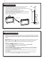
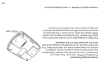
16
PG
Customer support:877-254-5625 or www.LockStateConnect.com
Notes on your system
1
PG
1
LS-90 Installation Guide
Caution
• Your thermostat is a precise instrument, handle it with care.
• Turn off electricity to the HVAC system before installing or
servicing thermostat or any part of the system.
• Do not turn electricity back on until work is completed.
• Do not short (jumper) across electric terminals at the control
on the furnace or air conditioner to test the system. This may
damage the thermostat.
• All wiring must conform to local codes and ordinances.
• This thermostat is designed for use with 24 volt AC and
millivolt systems (with a separate 24VAC power adapter).
• The thermostat relay load should be limited to 1.0 amp;
higher amperage may cause damage to the thermostat.
SAVE
ENERGY
NORMAL
$0.05 KW
H
FAN
12:30
5/25 WpEm
D
o
F
HVAC
STATUS
Power S
tatus N
TARGET
77o
TEMP
HUMI D
23%
HE AT
orm al
$.05/kW
h
MENU
Caution
To avoid electrical shock and to prevent damage to the
furnace, air conditioner, and thermostat, disconnect the power
supply before beginning work. This can be done at the circuit
breaker, or at the HVAC system.
ENGLISH
16
2
PG
2
TOOLS
You will need a small Phillips screwdriver and a drill with 3/16-in. (4.8mm) bit for wall mounts.
LOCATION
Replacement installations - mount the LS-90 in place of the thermostat. You must have a “C” wire or
other 24VAC power available at the LS-90 location. A new location will require moving your wiring.
New installations and for re-locating the LS-90 - follow the guidelines listed below:
• Locate the thermostat on an inside wall, about 5 ft. (1.5m) above the floor, and in a room that
is used often.
• Do not install it where there are unusual heating conditions, such as: in direct sunlight; near
a lamp, radio, television, radiator register, fireplace; near hot water pipes in a wall; or near a
stove on the other side of a wall.
• Do not locate in unusual cooling conditions, such as: on a wall
Good
separating an unheated room; or in a draft from a stairwell, door,
or window.
• Do not locate in a damp area. This can lead to corrosion that will
shorten thermostat life.
• Do not locate where air circulation is poor, such as: in a corner, an
5ft.
(1.5m)
alcove; behind an open door.
• Do not install the LS-90 until all construction and painting has
been completed.
• This thermostat does not require leveling.
3
REMOVE OLD UNIT
Switch OFF electricity to the furnace and air conditioner; then follow these steps.
• Remove cover from old thermostat. Most are snap-on types and simply pull off. Some have locking
screws on the side or front. These must be loosened. DO NOT remove wires. Note the letters
printed near the terminals. Attach labels (enclosed) to each wire for identification.
Caution
• Label the wires one at a time. You must label all the wires
before you proceed. With all wires labeled, remove them from
the old unit.
• Make sure the wires do not fall back inside the wall. You can
wind them around a pencil to keep them from falling.
• Loosen all screws on the old thermostat and remove it from the
wall.
W
Read instructions carefully before removing any wiring from
existing thermostat. Wires must be labeled before they are
removed. THERE IS NO STANDARD COLOR CODE. When removing wires from their terminals, ignore the color of the wires and
LABEL THEM by the terminal where they were screwed.
C
G
PG
3
4
PG
4
What wires do you have?
Make sure your wires are labeled. This may require you to nd the ‘other end’ connection for each
wire on your heating or air conditioning equipment and read the label there. Refer to the Wire
Reference page 13 for better understanding of wire labels from different HVAC system makers.
IMPORTANT: C wire or 24VAC power is required for the LS-90 to operate. If you do not have a C
wire you can run a new wire from the HVAC to the LS-90 or provide 24VAC power to operate the
LS-90 using a standard 24VAC wall transformer.
IMPORTANT: If you have both RH and RC you need to
remove the metal jumper-clip between these 2 terminals.
IMPORTANT: If you have both O and B you must check
page 13 for wiring info.
from furnace
Jumper
Clip
2.6"
Prepare wires
Screw terminal
C
Y
W
RH
G
Please follow these guidelines for safe and
secure wire connections:
• You will need at least 2.6” of wire for each of your connections to the LS-90.
• If you do not have enough wire, splice additional wire to allow enough slack.
• Fan out wires below the hole as shown.
• Remove insulation 1/8” from the tip of each wire.
• Take care not to damage the labels for each wire in handling.
5
From
Furnace
Caution
Do not allow wires to touch each other or parts on
thermostat.
C
W
Y
RH
G
• Fan wires out as illustrated with LS-90 below the
wall opening. As in the example: fan out the wires so
that the C wire is above the C terminal the W above
the W. This allows the LS-90 to t snug to the wall.
• Wires will position behind the LS-90 and up over the
terminal area.
• Do not bunch wires behind LS-90. Feed any slack
back into the wall opening.
Connect your wires
• Connect labeled wires only to a terminal with the
same letter label.
• Insert the wire in the terminal well and tighten the screw securely.
• Do not over-tighten, this will cut the wire.
• If a 24VAC transformer [Radio Shack PN273-1690] is used, connect to the C and RH terminals (no
polarity).
PG
5
6
PG
6
Mount the LS-90 to wall
Wall
1. Hold the LS-90 against the wall, with the wires coming over the top
above terminal block. The LS-90 will cover the hole in the wall.
2. Position LS-90 for best appearance. Use the optional stand- offs if more
LS-90
space for wires is needed behind the LS-90.
3. Attach the LS-90 to the wall with the screws provided.
4. If you are mounting the LS-90 to sheet rock or if you are using the old
mounting holes, use the plastic anchors provided.
5. Mark �rst and drill a 3/16-in.(4.8mm) hole for the insert at each screw
location, then mount the LS-90.
Wires
Screw to wall
C
W
Y
RH
G
Wall
anchor
7
HVAC Set-up on screen menu
With all the wires connected (including the C wire), it is time to turn the AC power back on. Do this at
the breaker you used to switch it off. The LS-90 will power-up in the control OFF mode. Your LS-90 is
not con�gured to operate your HVAC system yet. You must now use the menu driven HVAC SET-UP
function.
IMPORTANT: Make sure the LS-90 is powered up and is in the OFF mode before set-up. (To turn
Power button in the middle of the control bar to the right of the
your thermostat off, press the
display and touch OFF). Heating and cooling systems must be con�gured separately.
SET-UP for NORMAL systems (not a heat pump):
1. Press the purple MENU button on the control bar and then touch HVAC SET-UP.
2. Touch to highlight HEAT in the upper left corner of the display.
3. Touch to highlight NORMAL.
4. Select the appropriate number of stages for your heating system (from 1 to 3) by touching the
number of STAGES (in brackets) to highlight, and using the +/- buttons to increase or decrease.
5. Touch the appropriate FAN CONTROL setting.
Select HVAC if your heating system controls the fan (appropriate for most gas, oil, propane and
similar furnaces).
Select TSTAT if you want the thermostat to control the fan (for most electric heating systems).
6. Go on to con�gure COOL or press HOME to return to the Home screen.
PG
7
8
PG
8
SET-UP for NORMAL A/C cooling systems:
1. Press MENU and then touch HVAC SET-UP.
2. Touch and highlight COOL in the upper left corner of the display.
3. Select the number of stages of compression for your cooling system (1 or 2) by touching the
number of STAGES and using +/- buttons to increase or decrease.
4. Touch to select the appropriate FAN CONTROL setting HVAC or TSTAT.
NOTE: Most cooling systems require that the thermostat TSTAT control the fan.
.
5. Press HOME to return to the Home screen.
HVAC SET-UP 12:30pm WED 77
HEAT or COOL
STAGES
[1]
NORMAL
[1]
HEAT PUMP
[NONE]
AUXILIARY
AUX ELECT or GAS-OIL
FAN CTRL TSTAT
BACK>
SET-UP for HEAT PUMP systems:
1. Press MENU and then touch HVAC SET-UP.
2. Touch HEAT in the upper left corner of the display.
3. Touch HEAT PUMP.
4. Select the number of stages of compression for your heat pump system (1
or 2) by touching the number of STAGES, and using the +/- buttons to increase or decrease.
NOTE: Most heat pump systems have one stage of compression.
5. If you have AUXILIARY heat, touch the number of stages (default is [NONE] ) use the +/- buttons to
select 1-2 stages. (NOTE: The LS-90 controls a maximum of 3 stages total between pump and AUX.)
6. (If you have AUX) Select the type of auxiliary heat that you have - Electric or Gas-Oil.
NOTE: Most heat pump systems have electric heat strips for auxiliary heat.
7. Fan Control is set by the LS-90 (tstat) for heat pumps.
8. Press HOME button to return to the Home screen.
NOTE: For heat pump system your cooling is already con�gured since the heat pump unit provides
both heating and cooling.
9
Fan
control
Check HVAC system
Follow these procedures to verify you have correctly installed the
LS-90.
To check Fan (If you connected the G wire - fan relay):
1. Touch the FAN icon on the HOME screen and select ON.
2. Verify that air is blowing from the system. Return fan to AUTO
selection for normal operation. Press HOME.
SAVE
ENERGY
Temperature
+ / - Buttons
NORMAL
$0.05 KW
A
FAN
12:30pm
5/25 WED
o
F
HVAC
STATUS
Power St
TARGET
77o
TEMP
HUMID
23%
HEAT
ma l $.
05/kWh
atus Nor
MENU
To check HEAT mode:
and select HEAT.
1. Press the mode control
2. Press the + button to raise the target temp to 90 F. Allow the
system 2 minutes to respond
3. Verify that heat is blowing from the system.
Mode
control
o
4. Return mode control
to OFF (leave OFF for 4 minutes before checking COOL)
To check COOL mode (do not operate AC if outside temp is below 65 F):
o
1. Press the
mode control and select COOL.
2. Press the blue - button to lower the cool target temperature to 50 F.
Allow the system 5 minutes to respond.
3. Verify that cool air is blowing from the system.
o
4. Return
mode to OFF
PG
9
10
PG
Congratulations, you have successfully installed
your unit. Please proceed to the OPERATING
Guide to initialize the LS-90.
IMPORTANT: After you have labeled and connected your wires,
and followed the correct HVAC set-up, if these check procedures do
not operate your system call support at 1-877-602-5028 8am-12am EST.
SAVE
ENERGY
NORMAL
$0.05 KW
H
12:30pm
5/25 WED
FAN
o
F
HVAC
STATUS
Power S
TARGET
77o
TEMP
HUMID
23%
tatus N
10
HEAT
.05/kW
h
MENU
ormal $
LS-90 Features
This thermostat can be used with all 24VAC and millivolt
(24VAC external power) heating and cooling systems. It
cannot be used with line voltage systems. This thermostat is digital and your desired heat or cool
temperatures can easily be set on the large touch screen with the +/- buttons. A minimum 4 minute
off time protects heating and cooling compressors from damage. This thermostat uses a new
technique called sequential staging for more comfort with faster reaction to requested temperature
changes.
24VAC is Required This thermostat must be run on the HVAC systems 24VAC (C wire) or external 24VAC transformer
connected to the C and RH terminals. The 24VAC “C” wire is the other side of the 24VAC heating
transformer and can be found where the other thermostat wires connect at the wall or at the furnace.
Do not use the common or ground side of the line voltage.
11
Calibration Your thermostat was accurately calibrated at the
factory to ±1° F of actual ambient temperature.
You do have the option, however, to change the
display temperature to match that of a previous
thermostat, or to match another thermostat
already in your home, from ±1 - 9°F.
Calibrate controls
CALIBRATE
DELTA
FACTOR
-2
o
1 2 : 3 0 pmW E D7 5
o
F
To change your Thermostat Calibration:
1. Press MENU and then touch CALIBRATE
MENU
ACTUAL
2. Use the + / - buttons to adjust the displayed
T E M P DISPLAYED TEMP
.
temperature up or down, as desired.
77
<CONTRAST 5> BACK>
3. The DELTA FACTOR that appears on the
screen will also automatically increase or
decrease for each 1° adjustment. The large display will show the modi�ed temperature reading that
will be displayed on the HOME screen in normal operation.
4. Press HOME to return to the Home screen .
LCD Screen CONTRAST can be adjusted.
To change LCD Screen CONTRAST
From the CALIBRATE screen:
1. Select CONTRAST and adjust by touching the on-screen < and > controls for best viewing.
2. Press HOME to return to the Home screen.
PG
11
12
PG
Humidifier -
To use the /6 internal humidistat to control an external
humidifier unit, connect it as shown. Connect the H
terminal to the control leg of the humidifier relay. This
allows H to turn the humidifier ON and Off.
De-Humidifier -
To use the /6 internal humidistat to control an external
De-humidifier unit, connect it as shown. Connect the DH
terminal to the control leg of the dehumidifier relay. This
allows DH to turn the dehumidifier ON and Off.
Fresh Air The Fresh Air feature uses the EX relay to control a baffle
on a fresh external air source. Connect the 24VAC baffle
to C and EX terminals.
FOR EXTERNAL HUMIDIFIER
or DEHUMIDIFIER USING
HVAC SYSTEM's 24VAC
/60
RH
H or DH
FURNACE R
POWE R C
24VAC
FURNACE R
POWER C
FOR EXTERNAL HUMIDIFIER
or DEHUMIDIFIER USING
USING 24VAC ADAPTER
/60
RH
H or DH
FURNACE R
POWER C
To HUMIDIFIER
or
DEHUMIDIFIER
AC
ADPT
BAFFLE
To HUMIDIFIER
or
DEHUMIDIFIER
H or DH
RELAY
FOR FRESH AIR BAFFLE
/6
RH
EX
12
H or DH
RELAY
13
WIRE REFERENCE CHART
Your Wires
R or V or VR
RH or 4
RC
W
W2
W3
?
Y
Y2
G or F
C or X
E
L
T
H
DH
EX
B or
O
B and O
Lennox Heat Pump
V or VR or R
M or Y
Y or W or W2
F or G
R or O
LS-90 Terminal
RH and RC Single power for HEAT and COOL
RH Power for HEAT (RH not connected to RC jumper clip removed)
RC Power for COOL (RH not connected to RC jumper clip removed )
W Heat control
W2 2nd stage HEAT or heat pump auxiliary heat
W3 3rd stage HEAT or 2nd stage of 2 stage auxiliary heat
A 3rd wire for zoned hot water heat (see zoned systems pg14)
Y COOL control or 1st stage compression for heat pump.
Y2 2nd stage COOL control or 2nd stage compression for a heat pump
G FAN control
C Common 24VAC power (to power thermostat ) NOTE: TRANE uses B for this connection
n/a Emergency heat (do not connect, tape off)
n/a System monitor (do not connect, tape off)
n/a Outdoor sensor (do not connect, tape off)
External Humidifier
External De-Humidifier
External fresh air baffle
B Heat pump changeover (cool to heat, powered in heat)
O Heat pump changeover (heat to cool, powered in cool)
IMPORTANT: If there are both B and O wires (Trane pump
products) DO NOT CONNECT B to B terminal, connect B to C
terminal. If not a Trane product tape off B.
RH Power for HEAT
Y
W2
G
OX or X2 or C
Trane Products [American Standard]
B
C
W or W1 or X2
W2
C
PG
13
14
PG
14
Zoned Systems Reference
Your Wires
Radio Thermostat Terminal
2 wire Zoned Hot Water
R
RH
W
W
3 Wire Zoned Hot Water
Motor Driven Valves
R or 5
RH (power)
W or 4
W (heat ON)
Y or G or 6 (the 3rd wire) A (heat OFF)
3 Wire Zoned Hot Water
Solenoid Valves
R
RH (power)
W
A (heat ON)
Y or G (the 3rd wire)
W (heat OFF)
15
Notes on your system
Customer support: 877-602-5028 or www.radiothermostat.com
PG
15