1
Design, installation
& maintenance guide.
By Perry Continente
This publication is designed to provide accurate and informative
opinion in regard to the subject matter covered. It is distributed with the
understanding that the authors, publishers, and distributors are not engaged
in rendering engineering, hydraulic, agronomic, or other professional advice.
First Edition February 2003
Copyright 2003 The Toro Company (Ag Irrigation Business)
TABLE OF CONTENTS
CHAPTER 1:
Aqua-Traxx PC
Principles of Operation
Features and Advantages
Specifications
Use and Selection
CHAPTER 2:
Aqua-Traxx PC DESIGN
Selecting Aqua-Traxx PC Products
Submain Design
Mainline Design
Flushing and flushing submains
CHAPTER 3:
INSTALLATION AND STARTUP
Installation
Initial Startup
CHAPTER 4:
OPERATION AND MAINTENACE
Computing Irrigation Time
Monitoring System Performance
Maintenance Procedures for Aqua-Traxx PC Tape
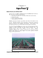
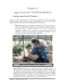
Chapter 1
PRINCIPLES OF OPERATION
Aqua-Traxx PC is a seamless, extruded drip tape with a molded emitter inserted in a
tube. The emitter is made up of the following:
• Filter inlets that which reduce the amount of debris that enter the emitter.
• Turbulent flow path.
• Pressure compensating chamber.
• Unique multiple laser slit outlets.
Seamless construction eliminates seam failures, and reduces the incidence of root
intrusion. Extrusion technology utilizes high-quality, extrusion-grade engineering
polymers renowned for their toughness and flexibility. These polymers were
developed specifically for use in harsh industrial and agricultural environments.
The exclusive flowpath molding process creates crisp, well-formed physical features,
resulting in excellent repeatability and high emission uniformity (EU). The
turbulent flowpath design reduces clogging in the flow channel. Pressure
responsive section provides a relatively constant flow rate within the operating
pressure range allowing for longer lengths of run and/or significant elevation
changes. (Flow exponent of 0.2).
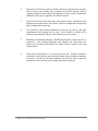
Broccoli in Salinas, Ca.
Chapter I: Aqua-Traxx PC Tape
- 1 -
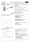
Aqua-Traxx Pc emitter
Aqua-Traxx PC emitter As shown above, water enters the flow path through the filter
inlets which are shaped like a reverse funnel. This keeps debris to the outside of the
emitter where it can be flushed away. Next, the water flows through the turbulent
flow channel before entering the pressure responsive section. The pressure
responsive section responds to changes in water pressure to maintain a constant flow
throughout the operating pressure range. Finally, the water exits through the lasermade multiple slit outlets to the crop. The multiple slits ensure the proper function
of the emitter and also provide the added benefit of significantly reducing the effect
of water running down the tube on slopes.
Chapter I: Aqua-Traxx PC Tape
- 2 -
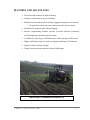
FEATURES AND ADVANTAGES
•
Precision molded emitter for high uniformity.
•
Seamless construction for greater reliability.
•
Multiple laser slit outlet Reduces startup clogging and impedes root intrusion.
o Dramatically reduces the water running down the tube on slopes.
•
Turbulent flow path provides reduced clogging.
•
Pressure compensating chamber provides increased Emission Uniformity
(EU) throughout the operating pressure range.
•
Available in a wide range of wall thicknesses, outlet spacings and flow rates.
•
Highly visible blue stripes for quality recognition and Emitter UP indicator.
•
Superior tensile and burst strength.
•
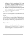
Tough, abrasion-resistant material reduces field damage.
Aqua-Traxx PC installation in Salinas, Ca.
Chapter I: Aqua-Traxx PC Tape
- 3 -
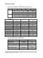
SPECIFICATIONS
Aqua-Traxx PC Diameter & Wall Thickness Dimensions
Diameter
5/8”
7/8”
Wall (mils)
8
10
12
15
10
12
15
Min PSI
4
4
4
4
4
4
4
Max PSI
16
20
22
25
18
20
22
Reel Length
7,500’
6,000’
5,100’
4,000’
4,400’
4,000’
3,000’
Reel Weight
63 lbs
60 lbs
58 lbs
61 lbs
65 lbs
61 lbs
62 lbs
Flow Rates
Part Number
Emitter flow rate @10
psi
Spacing, inch
Q-100 GPM/100’ @
10psi
6
8
12
16
18
24
0.67
0.50
0.34
0.25
0.22
0.17
6
8
12
16
18
24
0.90
0.67
0.45
0.34
0.30
0.22
0.20 gph emitter @ 10 psi
EAPXxx0667
0.20 gph
EAPXxx0850
0.20 gph
EAPXxx1234
0.20 gph
EAPXxx1625
0.20 gph
EAPXxx1822
0.20 gph
EAPXxx2417
0.20 gph
0.27 gph emitter @ 10 psi
EAPXxx0690
0.27 gph
EAPXxx0867
0.27 gph
EAPXxx1245
0.27 gph
EAPXxx1634
0.27 gph
EAPXxx1830
0.27 gph
EAPXxx2422
0.27 gph
(Check Toro Ag price list for available stock)
Flow path Specifications & Dimensions
Coefficient of Variation (CV)
Flow Exponent
Nominal Pressure
Inside diameter
Inside diameter
Operating Pressure Range
All emitters
All emitters
All emitters
5/8
7/8
4 – 25 psi
Hazen-Williams C Factor
Minimum filtration requirement
Main Tube
All emitters
Chapter I: Aqua-Traxx PC Tape
0.03
0.2
10 psi
0.635”
0.875”
See chart for different
mil thickness
140
200 mesh (74 micron)
- 4 -
USE AND SELECTION
Wall Thickness
8 mil - Intermediate products for general use in longer-term crops and average soil
conditions. Has an operating pressure range: 4 to 16 psi.
10 -15 mil - Heavy wall designed to be used in rocky soils, where insects and animals
may cause damage, or where the tape is to be used for more than one season.
Increased wall thickness provides for a wider operating pressure range. (See
specifications for mil thinness vs. operating pressure range.)
Spacing
6 and 8 inch - Used in closely spaced crops, on sandy soils, or where higher flow
rates are desired.
12 inch - Used on crops in medium soils and average crop spacings.
16 inch - Used on wide spaced crops where a longer length of run is desired.
24 inch - Used for widely spaced crops, heavy soils, long run lengths.
Flow Rate
0.27 gph Flow - Normally recommended for most crops and soils.
0.20 gph Flow - Recommended for longer runs on most crops and soils.
Diameter
5/8” - Used for average run lengths (0 to 1,000 ft).
7/8” - Used for long run lengths (up to 2,500 ft).
Slopes
Aqua-Traxx PC can be used in downward sloping, undulating or flat topographical
conditions. The pressure compensating feature allows for an operating pressure
range from 4 psi to 25 psi depending on the wall thickness. Use Aqua Flow program
for detailed hydraulic information.
Chapter I: Aqua-Traxx PC Tape
- 5 -
Chapter 2
Aqua-Traxx PC SYSTEM DESIGN
Selecting Aqua-Traxx PC Products
Aqua-Traxx PC is manufactured in a wide range of diameters, wall thicknesses, outlet
spacings, and flow rates to meet the specific requirements of various crops. Designers
should consider the following when selecting Aqua-Traxx PC products.
1.
Diameter - Aqua-Traxx is available in two diameters: 5/8” (0.635” I.D.) and 7/8”
(0.875” I.D.) and will fit standard fittings. The standard 5/8” diameter is used in
applications calling for standard run lengths of up to 1,000 feet depending on
topographical conditions. The 7/8” diameter is used on long run lengths of up to
2,500 feet or longer, again, depending on topographical conditions. Use the
Aqua Flow program for specific hydraulic information.
Aqua-Traxx PC on tomatoes in San Clemente, Ca.
2.
Wall Thickness determines how rugged and durable the product will be. In
addition, the upper range of the operating pressure range is also determined by the
wall thickness. (See specifications for more detailed information.) For short-term
vegetable crops, the experienced grower will generally be able to use the lightest
weight tubing. For longer-term crops a heavier wall thickness will be more resistant
to mechanical damage. Aqua-Traxx PC is manufactured in a range of wall
thicknesses: 8 mil, 10 mil, 12 mil, and 15 mil (one mil is 0.001 inch).
Chapter 2: Aqua-Traxx PC Tape
- 1 -
3.
Flow Rate selection will depend upon water quality, the availability of water, the
desired length of the tape, and the crop water requirement. Aqua-Traxx PC is available
in two emitter flow rates. These two flow rates are designated as 0.20 gph @ 10 psi and
0.27 gph @ 10 psi. It is advantageous to choose the lowest flow rate that will do the
job, because low flow rates minimize friction loss and allow for longer runs and better
uniformity. However, low flow rates may require a higher level of filtration.
4.
Outlet Spacing selection is often based upon the initial germination or growth needs of
the crop. For seeds or seedlings that are planted in a closely spaced pattern, it is
advantageous to use a tape product with closely spaced outlets. Soil type plays a major
role in the determination of outlet spacing, since the soil texture and condition
determines water movement and the shape of the wetted profile.
Computer Program AquaFlow
AquaFlow provides designers with the information they need to design an Aqua-Traxx PC tape
system for optimum performance. AquaFlow provides system operators with the information
necessary to operate the system, efficiently applying the desired amount of water and nutrients
to the crop.
AquaFlow will help you to design a complete Aqua-Traxx PC, Aqua-Traxx classic, DuraTraxx, Drip In classic and Drip In Pc systems. In addition, the AquaFlow program will also
calculate the flushing velocities and chemical travel time of the lateral. The program also
allows for the sizing of submains and mainlines. The AquaFlow program includes both metric
and U.S. measurement units in the graphic screens for pressure profile and flow profile curves.
Metric units are given in kPa and meters. U.S. units are given in psi and feet. Contact a Toro
Ag Irrigation representative to get a copy of AquaFlow.
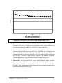
Design Considerations
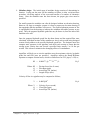
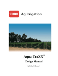
1. System capacity computations. It is recommended that the designer reduce the design
application rate by 5 percent when calculating system capacity to account for the
expected flow-rate decay of Aqua-Traxx PC. The flow rate will slowly decrease over
time to a value approximately 10% below the initial flow rate. Manufacturing QC
specifications are adjusted above the stated nominal flow rate to compensate for the
decrease in flow resulting in a flow rate of 5% below nominal.
Chapter 2: Aqua-Traxx PC Tape
- 2 -
Flow Rate v. Time
120
100
mL/6min
80
60
40
20
0
0
2
4
6
8
10
12
14
16
18
20
#8 hr Cycle
PC5081250
Polynomial Best Fit Line
Graph shows a decrease in flow rate over time of approximately 10%
2. Filtration requirement: Aqua-Traxx PC has a minimum filtration requirement of
200 mesh (74 micron). As with any micro irrigation product, water conditions may
require water treatment in addition to 200 mesh (74 micron) filtration.
3.
Lateral selection: Laterals are the length of tubing with emission devices or
emitters along that deliver the water to the crop. Aqua-Traxx PC is a drip tape with
emitters evenly spaced from 6 inches up to 24 inches. In selecting a lateral it is
recommended that the Emission Uniformity (EU) of a single lateral be greater than
90% in order to allow for some pressure variation in the submain if possible.
(Consult the AquaFlow program for more specific hydraulic information).
4. Lateral ends: Because Aqua-Traxx PC can be used on significant slopes, the affects
of system draining to the lowest points may be problematic and should be considered
in the design. Limiting the size and number of laterals on the submain will reduce
this affect. Also, using automatic flush caps at the end of the lateral and directing the
water that drains away from the crop.
Chapter 2: Aqua-Traxx PC Tape
- 3 -
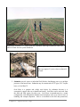
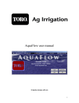
Installation in Salinas, Ca. Lateral ends have automatic flush caps installed to reduce the
effect of drain down at system shutdown.
Close-up picture of automatic flushing caps.
This cap requires 2.5 psi to close or almost 6 ft
of head.
5. Submains provide water to individual field blocks, distributing water at a uniform
pressure to the lateral lines. Submains may be constructed of PVC pipe, PVC Layflat
hose, or Oval Hose™.
Oval Hose is a popular and widely used choice for submains because it is
economical, rugged, and easy to handle and install. Oval Hose can be retrieved from
the field and used again year after year. Oval Hose is manufactured in a round
configuration, and subsequently flattened and wound on reels or in coils for ease of
handling and compact shipment. After it is installed in the field and pressurized,
Chapter 2: Aqua-Traxx PC Tape
- 4 -
Oval Hose returns to its round configuration. Aqua-Traxx PC tape may be connected
to Oval Hose submains using barbed connectors (FCA0798) or leader tubing.
Good submain design incorporates a flush out valve at the end of the submain.
Submain sizing: Because Aqua-Traxx PC can be used in difficult topographical
conditions, significant elevation changes along the submain need to be considered in
the design if they exist. (Consult the AquaFlow program for more specific hydraulic
information).
6. Connections: Aqua-Traxx PC can be connected in many different ways depending
on the submain material, PVC, Lay Flat, Oval hose, to name the most common.
Because Aqua-Traxx PC is a pressure compensating tape, longer runs and greater
flow rates per lateral are likely. The designer should be mindful of pressure losses in
the connections and a chart is provided below for illustrating flow vs. pressure loss
for the Toro oval hose fitting. If other fittings are used, contact the manufacture to
get flow loss data.
Aqua-Traxx PC tape is connected to Oval Hose submains using either a plastic fitting or a
length of leader tubing, as shown in Fig. 2. Fittings are popular because they are quickly and
easily installed, they provide a strong and rugged connection, and they can be re-used for
many years.
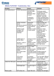
Methods of Aqua-Traxx Tape Connections. Friction loss table for Toro Ag Irrigation
oval hose fitting part number, FCA0798 on next page.
Chapter 2: Aqua-Traxx PC Tape
- 5 -
Flow Rate (GPM)
1
1.5
2
2.5
3
3.5
4
FCA0798
0.23 psi
0.49 psi
0.83 psi
1.25 psi
1.74 psi
2.31 psi
2.95 psi
Friction Losses in PSI through Tape Connections
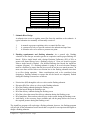
7. Submain Riser Design
A submain riser serves to regulate water flow from the mainline to the submain. A
typical submain riser assembly will normally consist of:
1.
2.
3.
A manual or pressure regulating valve to control the flow rate.
A vacuum relief valve to prevent suction in the submain and tape lines.
A Schrader valve to be used as a pressure test point.
8. Flushing requirements and flushing submains: As a general rule, flushing
velocities of one foot per second or greater are required to ensure proper flushing of a
lateral. With a single lateral with a design Emission Uniformity (EU) of 90% or
greater will almost always have a flushing velocity of 1 foot per second or greater
when a single lateral is flushed. (For detailed flushing data consult the AquaFlow
computer program.) If a flushing submain is going to be used elevation changes
must be considered to ensure that the lower areas do not have too much pressure. In
most cases there will be little to not friction loss in the flushing submain since there
is no flow during operation. Other considerations need to be considered when
designing a flushing submain to ensure that all the lateral are adequately flushed
during the flushing event and are as follows:
•
•
•
•
•
•
•
•
Friction loss (Hf) through the valve or valves on the flushing submain.
Elevation Hf of the valves or valves on the flushing submain.
Hf of the flushing submain during the flushing event.
Hf of the lateral during the flushing event.
Hf of the delivery submain during the flushing event.
Hf of the valves that control the delivery submains during the flushing event.
Hf of mainlines, filters and any other devices in the system during the flushing event.
And finally, is the necessary water available and can the pump deliver the water at
the required pressure during the flushing event?
The AquaFlow program will not design a flushing submain; however, the flushing program
will provide all the information from a lateral that is required for an experienced designer to
design a flushing submain.
Chapter 2: Aqua-Traxx PC Tape
- 6 -
9. Mainline design: The initial stage of mainline design consists of determining its
location. Laying out the route for the mainline to follow is often a trial-and-error
procedure, involving analysis of the costs and benefits of a number of alternative
routes. Once the mainline route has been chosen, the proper pipe sizes must be
specified.
For small systems the mainline can often be designed without an elevation drawing.
However, for large or complex systems it is best to prepare an elevation drawing of
the topography that the mainline will traverse. The required submain pressure in feet
is superimposed on the drawing to indicate the minimum allowable pressure at any
point. Then, the proposed hydraulic grade line may be drawn in, from the inlet of the
mainline to the end.
Once the proposed hydraulic grade line has been drawn and the required flow rates
calculated, individual sections of the mainline are sized, each section being designed
to most closely adhere to the specified hydraulic grade line. The designer must also
compute static pressures in the pipelines, and check each section to ensure that the
average water velocity does not exceed a specified limit, usually 5 to 10 feet per
second. This is done to minimize the damaging effects of waterhammer.
AquaFlow will help you to size the mainline once the maximum velocity, hydraulic
grade line and flow rates are specified. AquaFlow utilizes the Hazen-Williams
equation to compute friction losses, which is recalled here for PVC pipe (C=150) as,
Hf = 0.000977 {Q 1.852 / D 4.871} L
Where: Hf
Q
D
L
=
=
=
=
Eq. 5
Friction Loss (feet of water)
Flow Rate (gpm)
Actual Pipe I.D. (inches)
Length of Pipe (feet)
Velocity of flow in a pipeline may be computed as follows,
V = 0.4085Q/D2
Eq. 6
Where: V = Velocity (ft per second)
Q = Flow Rate (gpm)
D = Actual Pipe I.D. (inches)
Chapter 2: Aqua-Traxx PC Tape
- 7 -
Chapter 3
INSTALLATION AND STARTUP
PROCEDURES
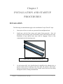
INSTALLATION
The following recommendations apply to the installation of Aqua-Traxx PC tape:
1.
Store tape reels in a covered area, protected from sunlight and rain.
2.
Install tape with the blue stripes and outlets facing upwards. Fine soil
particles in the incoming water will normally settle to the bottom of the tape.
Installation of tape upside down may result in clogging if there is any
contamination in the incoming water.
Aqua-Traxx PC, install Blue Stripes up
3.
An air/vacuum relief valve should always be installed at the submain riser to
prevent suction from occurring in the tape when the system is shut down.
Suction in buried tape will tend to draw muddy water back into the tubing
through the outlets, causing contamination.
Chapter 3: Installation and Startup
- 1 -
4.
Tape may be laid on the surface or buried. Burial is preferred where possible,
since it protects the tubing from accidents and animal damage, reduces
clogging, maintains tape location and alignment, reduces surface evaporation,
and insures that water is applied at the desired location.
5.
Tape must be buried when used under clear plastic mulch. Condensed water
droplets on the underside of clear plastic will focus sunlight like a magnifying
glass, burning holes in the tape.
6.
Care should be taken during installation to prevent soil, insects, and other
contaminants from getting into the tape. Ends should be closed off by
kinking or knotting until the tape can be hooked up to the system.
7.
Mainlines and submains should be flushed thuraly before Aqua-Traxx PC is
connected. After flushing Mainlines and submains the Aqua-Traxx PC
laterals can be connected and flushed to ensure that the system is free form
contamination.
8.
Tape must be monitored as it is injected into the soil. Someone should be
watching to insure that the tape maintains its blue stripes upwards orientation,
to assist in case the tape becomes tangled in the injector, and to signal the
tractor driver when the tape reel is empty and must be replaced.
Chapter 3: Installation and Startup
- 2 -
Initial startup:
1.
Flow rate: The first time you run Aqua-Traxx PC you may experience a flow
rate that is approximately 5% higher than nominal. As previously stated in
Chapter 2, Aqua-Traxx PC will have decay in the flow rate over time of
approximately 10%. The production QC has been adjusted to 5% higher than
nominal to account for this.
2.
Startup squirting: The first time Aqua-Traxx Pc is charged to begin irrigating
a small amount of squirting out of the emitters may occur for the first one or
two irrigations before diminishing to no squirting. The squirting is normally
no more than one or two inches high and will diminishes as the laser outlets
relax.
Aqua-Traxx PC in Bell Peppers, Woodland, Ca.
Chapter 3: Installation and Startup
- 3 -
Chapter 4
OPERATION AND MAINTENANCE
COMPUTING IRRIGATION TIME
Once ET has been determined, the irrigation time T may be computed. In order to
perform the calculation, it is necessary to know the average Q100 flow rate (gpm per
100 feet) and the system Emission Uniformity EU.
For row crops on Aqua-TraXX tape, the irrigation time T may be computed from the
following formula:
S x ET
Q-100 x EU
T
=
1.04 x
Where T
S
ET
Q-100
EU
=
=
=
=
=
Irrigation Time (hours)
Average Tube Spacing (feet)
Evapotranspiration (inches)
Average Q100 Flow Rate (gpm per 100 feet)
System Emission Uniformity (decimal)
Eq. 7
Aqua-Traxx PC in Tomatoes in San Clemente, Ca.
Chapter 4: Operation and Maintenance
- 1 -
EXAMPLE:
In a field of Pima cotton growing in Arizona, the previous day's ET value was found
to be 0.221 inches. The cotton rows are spaced 40 inches (3.33 feet) apart with
Aqua-TraXX tape buried under each row. The average flow rate is 0.30 gpm per 100
feet, and the system emission uniformity is 90 percent. Find T:
SOLUTION:
T
=
1.04 x
3.33 x 0.221
0.30 x 0.90
=
2.8 hours
On newly planted acreage, the computed ET, and therefore the irrigation time T, may
be quite low. Nevertheless, because the young plants are not likely to have extensive
root systems, it is best to apply this small amount on a frequent basis rather than
attempting to apply more water less frequently. On established crops, however, it is
usually best to have a minimum irrigation period of one hour or longer. This
minimizes uneven distribution due to mainline fill and drain times and establishes a
larger wetting pattern under each tape outlet. For example, if the irrigation time is
determined to be 35 minutes for a given day, it would probably be better to
accumulate the time for two days and irrigate 70 minutes every other day.
MONITORING SYSTEM PERFORMANCE
The well-designed micro-irrigation system will have built-in diagnostic tools that
will allow the operator to monitor the performance of the system, and to detect
possible problems in the early stages. Included in this category are flow meters,
pressure gauges, and submain riser filters.
Flow Meters
System flow meters should be installed on the main supply lines, and should provide
readings of both instantaneous and cumulative flow. These meters should be read
regularly and the readings kept in a logbook. Variations in the system flow rate may
indicate that something in the system is amiss.
For example, a gradual decline in system flow rate as measured by the flow meters
may indicate a problem with the pumping station or a clogging problem in the field.
On the other hand, an unexpected increase in the system flow rate might be an
indication of a pipeline break or the presence of leakage in the system.
Measurements of cumulative flow will serve to verify water application schedules.
Chapter 4: Operation and maintenance
- 2 -
Pressure Test Points
The system should have sufficient pressure testing points so that an overall check of
the system pressures can be made. Widely differing pressures in different sections of
the system may indicate that some blockage, leakage, or other problem has arisen in
some section of the system. Pressure checks should be regularly made, and the
pressures recorded.
Submain Riser Filters
Submain riser filters are small, in-line or “wye” strainers installed at each submain
riser. Under normal conditions these filters, which are usually 80 - 120 mesh, will
collect few if any contaminants because the main filtration system will normally have
removed this material. Periodic examination of these riser filters can be a valuable
indication that the system is contaminated. In the case of a pipeline break or a failure
of the main filter station, riser filters will help to prevent foreign material from
entering the tape lines.
MAINTENANCE PROCEDURES FOR Aqua-Traxx PC Tape
Flushing
In many micro-irrigation systems it has been found that provisions must be made to
flush submain lines and lateral lines to remove settled sediments, and flushing
constitutes an important maintenance routine. Research has shown that most settled
sediments can be flushed from pipe or tubing with a flow velocity of one foot per
second, which is referred to as the "scour velocity". In standard half-inch lateral
lines, the 1 ft/sec scour velocity is equivalent to a flow rate of 1 gpm at the
downstream end.
Mainlines, submains and lateral lines should be flushed thoroughly prior to system
startup, and tape lines should be regularly flushed during the season. Open the ends
of the lateral lines while the system is running and allow water to run into a container
until it runs clear. Collect some of the dirty water in a glass jar, and examine it
carefully. Take note of the nature of the impurities in the water. If there is a
significant amount of contaminant in the flush water, find out what it is. Does it
appear to be a bacterial slime? Are large aggregated particles present? Is there
evidence of iron precipitation? Is there any material which could be sand from the
media filter?
Examine the contaminant under a microscope. Put samples of the dirty water into
two small jars or test tubes. Treat one with a few drops of chlorine bleach and the
Chapter 4: Operation and Maintenance
- 3 -
other with a few drops of hydrochloric acid. Note any changes: chlorine will attack
organic matter, while acid will dissolve many inorganic precipitates. Acid or
chlorine will not affect soil and sand particles.
Prevention of Clogging
The biggest potential problem facing the operator of a micro-irrigation system is
clogging. Because the water passages in most tape emitters are very small, they
easily become clogged by particles of mineral or organic matter. This can reduce
emission rates, cause non-uniformity of water distribution, and thereby cause stress
and damage to the crop.
Growers sometimes inadvertently cause clogging by injecting inappropriate
chemicals or other substances into their systems.
In some cases, contaminants are present in irrigation water delivered to the user and
are not adequately filtered out. These contaminants may include soil particles, living
or dead organic materials, and scale from rusty pipes. In other cases, contaminants
enter the system during the installation phase, and are not adequately flushed out of
the system. Included in this category are insects, Teflon tape, PVC pipe shavings,
and soil particles. Pipeline breaks often result in system contamination with soil,
causing subsequent clogging problems.
In buried systems, soil particles may enter, or be sucked into, tape outlets. Roots
may grow into these buried outlets to plug them.
Finally, contaminants may grow, aggregate, or precipitate in water as it stands in the
lines or evaporates from tape outlets between irrigations. Iron oxide, manganese
dioxide, calcium carbonate, algae, and bacterial slimes can form in micro-irrigation
systems under certain circumstances.
The solution to a particular clogging problem must be based upon the nature of the
problem. Acid treatment has been used successfully to dissolve calcium precipitates,
and chlorine is frequently used to decompose organic materials.
Once a system is badly clogged, there is usually little that can be done to fix it.
Therefore, the wisest course is to prevent clogging in the first place. Experience has
shown that most clogging problems can be avoided by following a few simple rules:
1.
Analyze the source water for suspended and dissolved solids, and design the
irrigation, chemical injection, and filter systems accordingly.
2. Install secondary filters on submain risers to protect the system from pipeline
breaks or filter system failures.
3. Install vacuum breakers on submain risers to prevent suction in lateral lines.
Chapter 4: Operation and maintenance
- 4 -
4. Take care during installation to minimize contamination by soil, insects, pipe dope,
PVC pipe shavings, and the like.
5. Thoroughly flush the system before connecting tape to submains.
6. Practice regular chemical treatment (acid or chlorine).
7. Flush tape lines on a regular basis.
Prevention of Insect Damage
Ants, wireworms, and other insects may cause damage to tape. Insect damage typically
takes the form of holes chewed through the sides of tape. Researchers have noted that insect
damage is most severe in tape having wall thicknesses of less than 10 mils (0.010 inches).
Insect damage has been successfully controlled with insecticides. However, these chemicals
are highly toxic and persist in the environment. For this reason, growers are advised to
select a tape with sufficient wall thickness to prevent insects from making holes through the
wall of the tubing.
Prevention of Root Intrusion
In micro-irrigation systems utilizing buried tape, plant roots may grow into tape outlets,
effectively clogging them. This so-called “root intrusion” into tape outlets may be
widespread throughout the field, severely compromising the effectiveness of the irrigation
system. In advanced cases, there is no alternative but to replace the tape.
The tendency for root intrusion to occur varies widely according to crop type, the type of
system components selected, depth and placement of the drip tape, and irrigation scheduling
practices. It is known that moisture stress encourages plant root structures to expand more
aggressively, seeking water. It is also known that roots will find and follow a seam on
buried drip tape, and grow into outlets if they are placed along this seam.
Two of the most effective preventive measures against root intrusion are to schedule
irrigation in such a way as to avoid moisture stress, and to select tape types which do not
have a seam. Drip tapes employing slit type outlets are considerably less susceptible to root
intrusion than are those with hole type outlets.
Other measures employed against root intrusion are chemical treatments with acid,
acidic fertilizers, chlorine, or chemicals, which retard root growth. It must be noted that this
type of chemical treatment, because it is used to retard the roots of the crop, may lead to
serious crop damage if done incorrectly. Growers are strongly encouraged to seek expert
advice before attempting chemical treatments to discourage root intrusion.
Chapter 4: Operation and Maintenance
- 5 -