1
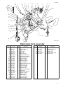
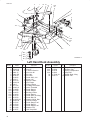
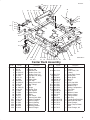
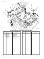
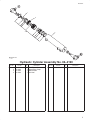
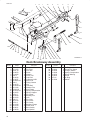
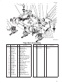
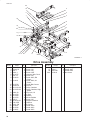
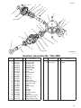
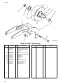
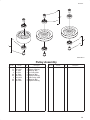
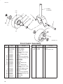
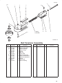
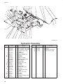
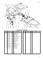
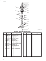
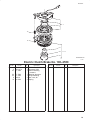
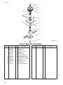
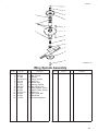
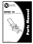
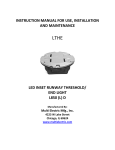
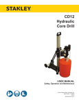
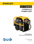
Form No. 3326-597 126in Quadfloat Mower Groundsmaster 455–D Model No. 30402—210000001 and Up Parts Catalog Ordering Replacement Parts To order replacement parts, please supply: the part number, the quantity, and the description of each part desired. Understanding Reference Numbers Each identified part in an illustration has a reference number. The reference number for a part also appears in the parts list, along with other information about the part. This catalog uses two special reference number formats, one to indicate parts in a service assembly and another to indicate the quantity of a given part in an illustration. Service Assembly Reference Numbers Parts in service assemblies have reference numbers in the form a:b. The a represents the reference number of the entire service assembly and the b represents a sequential number unique to each part within the service assembly. For example, a wheel assembly might be identified by reference number 6, the tire by 6:1, the valve by 6:2, and the wheel by 6:3. When you order the assembly identified by reference number 6, you receive all parts identified by reference numbers 6:1, 6:2, and 6:3. However, you may also order any part individually. Reference numbers of this type appear in illustrations and in part lists. Reference Numbers Indicating Quantity In an illustration, if a reference number indicates more than one part, the reference number has the form nX y. The n represents the quantity of the part, the X is the multiplication symbol, and the y represents the reference number. For example, in an illustration, the reference number 2X 37 means that two of the parts identified by reference number 37 are indicated. The TORO Company — 2001 All Rights Reserved 3326–597 Contents Description Page Right Hand Deck Assembly . . . . . . . . . . . . . . . . . 3 Left Hand Deck Assembly . . . . . . . . . . . . . . . . . . 4 Center Deck Assembly . . . . . . . . . . . . . . . . . . . . . 5 Hydraulic Cylinder Assembly No. 86–2190 . . . . 7 Deck Breakaway Assembly . . . . . . . . . . . . . . . . . 8 Trap Door Assembly . . . . . . . . . . . . . . . . . . . . . . . 9 Drive Assembly . . . . . . . . . . . . . . . . . . . . . . . . . . . 10 Gearbox Assembly No. 100–2585 . . . . . . . . . . . 11 Rear Castor Assembly . . . . . . . . . . . . . . . . . . . . . 12 Description Page Pulley Assembly . . . . . . . . . . . . . . . . . . . . . . . . . . 13 Front Castor Assembly . . . . . . . . . . . . . . . . . . . . . 14 Belt Tensioner Assembly . . . . . . . . . . . . . . . . . . . 15 Hydraulics Assembly . . . . . . . . . . . . . . . . . . . . . . . 16 Covers Assembly . . . . . . . . . . . . . . . . . . . . . . . . . . 17 Clutch Spindle Assembly . . . . . . . . . . . . . . . . . . . 18 Electric Clutch Brake No. 100–2559 . . . . . . . . . . 19 Center Spindle Assembly . . . . . . . . . . . . . . . . . . . 20 Wing Spindle Assembly . . . . . . . . . . . . . . . . . . . . 21 Part Description Abbreviations Part descriptions in this catalog may include the following abbreviations. Abbreviation AR . . . . . . . . . . . . . . . . . ASM . . . . . . . . . . . . . . . . CARR . . . . . . . . . . . . . . DEG . . . . . . . . . . . . . . . . FH . . . . . . . . . . . . . . . . . GA . . . . . . . . . . . . . . . . . HF . . . . . . . . . . . . . . . . . HH . . . . . . . . . . . . . . . . . HHF . . . . . . . . . . . . . . . . HLH . . . . . . . . . . . . . . . . HJ . . . . . . . . . . . . . . . . . . HOC . . . . . . . . . . . . . . . . HS . . . . . . . . . . . . . . . . . HSBH . . . . . . . . . . . . . . HSFH . . . . . . . . . . . . . . . HSH . . . . . . . . . . . . . . . . HWH . . . . . . . . . . . . . . . HWHTF . . . . . . . . . . . . . 2 Meaning as required assembly carriage degrees flat head gauge hex flange hex head hex head flange hex lag head hex jam height-of-cut hex socket hex socket button head hex socket flat head hex socket head hex washer head hex washer head thread forming Abbreviation HYD . . . . . . . . . . . . . . . . INC . . . . . . . . . . . . . . . . . LH . . . . . . . . . . . . . . . . . NI . . . . . . . . . . . . . . . . . . PPH . . . . . . . . . . . . . . . . PTH . . . . . . . . . . . . . . . . PTO . . . . . . . . . . . . . . . . RH . . . . . . . . . . . . . . . . . SFH . . . . . . . . . . . . . . . . SHH . . . . . . . . . . . . . . . . SQH . . . . . . . . . . . . . . . . SHWH . . . . . . . . . . . . . . SPH . . . . . . . . . . . . . . . . SRH . . . . . . . . . . . . . . . . STD . . . . . . . . . . . . . . . . TAP . . . . . . . . . . . . . . . . TTH . . . . . . . . . . . . . . . . WH . . . . . . . . . . . . . . . . . Meaning hydraulic incorporated left hand nylon insert Phillips pan head Phillips truss head power take off right hand slotted fillister head slotted hex head square head slotted hex washer head slotted pan head slotted round head standard self tapping Torx truss head wing head 3326–597 10:4 10 2 9:6 9:2 1 19 4 11 3 11 9:7 6 9:3 18 5 21 15 10:3 10:2 8 10:1 9 22 9:5 17 9:4 13 9:1 3 12 11 16 9:2 19 23 Sheet No.:2 24 Right Hand Deck Assembly Ref. No. 1 2 3 4 5 6 8 9 9:1 9:2 9:3 9:4 9:5 9:6 9:7 10 10:1 10:2 10:3 10:4 11 12 13 15 16 17 Part No. 3216–6 93–9413 323–13 86–2010 3290–256 3296–15 100–2588 92–7758 32148–10 43–8480 66–1340 69–6470 85–6410 86–0700 86–0760 92–9727 92–5581 92–5583 92–9726 92–8861 86–2600–01 69–1510 302–5 32128–54 32128–29 93–7814 Qty. 1 1 3 1 1 1 1 1 1 2 1 2 1 1 1 1 1 1 1 1 4 5 1 1 1 1 Description Screw–HH Decal–HOC, Int’l Screw–HH Pin–HOC Pin–Hair Nut–Lock NI V–Belt, B–Section RH Wing Deck ASM Insert–Threaded Decal–Danger Decal–Danger Bushing–Castor Decal–Danger Decal–HOC, RH Wing Decal–Belt, RH HOC Cap ASM Ring–Retaining Washer–Cap Spring–Compression Cap–HOC Washer–Guide, Belt Spacer–Castor Fitting–Grease Nut–Flange Locknut–Flange Decal–Danger Ref. No. 18 19 21 22 23 24 Part No. 93–7824 93–7815 86–1440 3256–35 93–7208–01 32144–11 Qty. 1 2 2 1 1 10 Description Decal–Danger, Int’l Decal–Danger, Int’l Washer–Flat Washer–Flat Shield–Deck, Wing Screw–TAP 3 3326–597 2 1 16 21 12 3 15:3 20 4 5 1 6 16 15:1 7 15:6 15:2 18 15 24 8 23 18 14 15:2 15:7 11 15:4 15:5 17 19 22:4 22 23:3 22:2 22:1 Sheet No.:3 Left Hand Deck Assembly Ref. No. 1 2 3 4 5 6 7 8 11 12 14 15 15:1 15:2 15:3 15:4 15:5 15:6 15:7 16 17 18 19 20 21 22 4 Part No. 323–13 32128–19 100–2588 3296–15 3290–256 86–2010 93–9412 3216–6 69–1510 32128–54 302–5 92–7756 32148–10 43–8480 66–1340 69–6470 85–6410 86–0710 86–0750 86–2600–01 32128–29 93–7815 93–7814 93–7824 86–1440 92–9727 Qty. 2 2 1 1 1 1 1 1 5 1 1 1 1 2 1 2 1 1 1 3 1 2 1 1 2 1 Description Screw–HH Nut–HF V–Belt, B–Section Nut–Lock NI Pin–Hair Pin–HOC Decal–HOC, Int’l Screw–HH Spacer–Castor Nut–Flange Fitting–Grease LH Wing Deck ASM Insert–Threaded Decal–Danger Decal–Danger Bushing–Castor Decal–Danger Decal–HOC, LH Wing Decal–Belt, LH Washer–Guide, Belt Locknut–Flange Decal–Danger, Int’l Decal–Danger Decal–Danger, Int’l Washer–Flat HOC Cap ASM Ref. No. 22:1 22:2 22:3 22:4 23 24 Part No. 92–5581 92–5583 92–9726 92–8861 93–7208–01 32144–11 Qty. 1 1 1 1 1 10 Description Ring–Retaining Washer–Cap Spring–Compression Cap–HOC Shield–Deck, Wing Screw–TAP 7 1 32 2 39 38 46 6 3326–597 20 25:8 38 40 49 20 3 4, 5 9 14 48 15 30:4 30:3 30:2 30 17 47 30:1 18 25:5 25:7 36 19 20 35 51 33 52 22 21 23 24 25:9 2 25:2 45 25:1 25:4 25:6 44 42 29 50 20 19 28 27 26 25:3 25 Sheet No.:4 Center Deck Assembly Ref. No. 1 2 3 4 5 6 7 9 14 15 17 18 19 20 21 22 23 24 25 25:1 25:2 25:3 25:4 25:5 25:6 Part No. 32128–19 325–35 3256–26 86–2230–01 86–2260–01 86–2190 32121–51 94–8008 3290–256 94–8009–01 32128–54 86–2390 86–1890–03 32144–26 57–0690 57–0680 29–4820 3272–11 92–7757 32148–10 43–8480 55–4300 68–8340 69–6470 85–6410 Qty. 2 4 4 1 1 2 2 2 2 2 2 2 4 12 2 2 2 2 1 1 1 2 1 4 1 Description Nut–HF Screw–HH Washer–Flat Guide–Cover, RH Guide–Cover, LH Cylinder–Lift, Wing Pin–Roll Plate–Wear Pin–Hair Strap–Deck, HOC Nut–Flange Pin Hinge Screw–Flow Pin–Special Shaft–Roller Roller Pin–Cotter Center Deck ASM Insert–Threaded Decal–Danger Decal–Warning Decal–Torque Bushing–Castor Decal–Danger Ref. No. Part No. 25:7 86–0720 25:8 86–0730 25:9 26 27 28 29 30 30:1 30:2 30:3 30:4 32 33 35 36 38 39 40 42 44 86–0740 3234–1 68–6840 32128–21 68–6710 92–9727 92–5581 92–5583 92–9726 92–8861 32128–23 77–0950 69–1510 302–5 84–5300 92–5810–03 92–5811–03 93–7814 93–7818 45 93–7815 Qty. Description 1 Decal–HOC, LH Center 1 Decal–HOC, RH Center 1 Decal–Belt, Center 1 Screw–HHF 1 Shaft–Roller 1 Nut–HF 1 Roller 2 HOC Cap ASM 1 Ring–Retaining 1 Washer–Cap 1 Spring–Compression 1 Cap–HOC 4 Nut–HF 2 Washer–Castor 10 Spacer–Castor 2 Fitting–Grease 4 Nut–Jam 2 Female Rod End ASM 2 Male Rod End ASM 1 Decal–Danger 1 Decal–Torque, Blade Bolt 1 Decal–Danger, Int’l 5 3326–597 7 1 32 2 39 38 46 6 20 25:8 38 40 49 20 3 4, 5 9 14 48 15 30:4 30:3 30:2 30 17 47 30:1 18 25:5 25:7 36 19 20 35 51 33 52 22 21 23 24 25:9 2 25:2 45 25:1 25:4 25:6 44 42 29 50 20 19 28 27 26 25:3 25 Sheet No.:4 Center Deck Assembly (Continued) Ref. No. 46 47 48 49 50 51 52 6 Part No. 86–2510–01 86–1440 3296–29 322–21 94–8020–03 32144–11 93–7207–01 Qty. 2 4 4 4 2 14 1 Description Spring–Comp, Lift Washer–Flat Nut–Lock NI Screw–HH Shield–Harness, Wire Screw–TAP Shield–Deck, Center Ref. No. Part No. Qty. Description 3326–597 1 2 4 3 Sheet No.:A1 T–1464 Hydraulic Cylinder Assembly No. 86–2190 Ref. No. 1 2 3 4 Part No. 92–0603 92–0604 92–0602 92–0600 Qty. 1 1 1 1 Description Ref. No. Part No. Qty. Description Rod/Piston Head–Ring, Snap Barrel ASM Kit–Seal 7 3326–597 7 8 1 10 2 3 4 5 6 9 11 12 13 15 14 16 34 33 32 30 29 28 27 26 25 31 24 23 21 20 19 18 17 Sheet No.:5 22 Deck Breakaway Assembly Ref. No. 1 2 3 4 5 6 7 8 9 10 11 12 13 14 15 16 17 18 19 20 21 22 23 24 25 26 8 Part No. 3296–29 84–1350 3218–18 60–9870 53–6380 323–4 92–4036 92–4037 84–0800–01 302–5 86–2070 86–2080–01 86–1440 32128–54 86–2560–01 86–2650 3272–5 86–2090 86–2150 283–61 86–2130 3272–9 86–2180 86–2120 94–8031 94–8029 Qty. 4 4 2 2 4 4 2 2 4 4 4 4 8 4 2 2 6 6 2 6 2 2 4 4 2 2 Description Nut–Lock NI Pin–Pivot Nut–Jam Screw Washer Screw–HH Cap–Rod Capscrew–HSH Arm–Pivot Fitting–Grease Nut Joint–Ball Washer–Flat Nut–Flange Spring–Compression Spring–Support Pin–Cotter Bushing–Pm Lock Pin–Yoke Pin–Clevis Pin–Cotter Bushing–Flange Roller–Lock Boot–Switch Nut–Special Ref. No. 27 28 29 30 31 32 33 34 Part No. 237–7 94–8023 94–8024 43–8600 93–6674 43–8610 237–42 72–4320 Qty. 2 2 2 2 2 2 2 2 Description O–Ring Guide–Pin, Switch Plunger–Switch Spring–Compression Decal–Warning Guide O–Ring Switch 3326–597 1 2 27 2 3 4 2 17 27 5 6 26 29 8 7 9 10 11 12 13 2 27 25 24 23 15 16 19 18 16 20 14 28 Sheet No.:6 Trap Door Assembly Ref. No. 1 2 3 4 5 6 7 8 9 10 11 12 13 14 15 16 17 18 19 20 23 24 25 26 27 Part No. 32128–19 323–13 86–1820–01 32144–70 3296–25 32121–11 86–2400–01 325–5 86–1560 86–1490 3220–12 86–1570 3220–5–01 86–1550 3296–25 3256–26 92–7766–01 92–4033–01 256–243 325–7 3290–467 86–2590 237–141 48–7081 86–2600–01 Qty. 2 4 1 2 2 2 2 2 2 2 2 2 2 2 2 4 1 2 2 2 2 2 4 2 4 Description Nut–HF Screw–HH Bracket–Pulley Screw–HH Nut–Lock NI Pin–Roll Latch–Arm Screw–HH Spacer–Cylinder, Lift End–Rod, LH Thread Nut–HJ, LH Thread Rod–Threaded Nut–HJ End–Rod, RH Thread Nut–Lock NI Washer–Flat Bracket – Pulley Trap–Door Bearing–Flange Screw–HH Pin–Hair Rod–Clutch Grommet–Rubber Grip–Plastic Washer–Guide, Belt Ref. No. Part No. 28 3290–378 29 3290–483 Qty. Description 2 Tie–Cable 2 Washer 9 3326–597 20 19 2 5 3 7 4 18 6 26 3 16 21 22 17 15 8 9 27 13 12 29 11 10 29:2 23 Sheet No.:7 Drive Assembly Ref. No. Part No. Qty. 2 3 4 5 6 7 8 86–1830 32144–70 325–7 3234–1 95–4375 323–14 93–9410 1 3 2 4 1 2 1 9 93–9411 * 10 1 10 11 12 *12 86–0740 32128–23 86–1410–03 86–3100–03 1 2 1 1 13 15 16 17 18 19 20 21 22 23 23 3296–39 86–1970 86–1990 84–1550 325–9 86–2020–01 100–2585 2412–138 93–6697 86–0780 93–9421 2 1 6 4 2 1 1 1 1 1 1 Not illustrated Description Cover–Driveshaft Screw–HH Screw–HH Screw–HHF Harness–Wire, Deck Screw–HH Decal–HOC, RH Center Decal–HOC, LH Center Decal–Belt, Center Nut–HF Pulley–Gearbox Pulley–Gearbox, High Speed Nut–Lock, NI V–Belt Washer Mount–Rubber Screw–HH Support–Gearbox Gearbox R–Clamp Decal–Lube Decal–HOC Decal–HOC Ref. No. Part No. Qty. 26 27 29 29:2 2412–150 3234–1 100–2591 32148–9 1 2 1 2 Description J–Clip Screw–HHF Shield ASM Nut–Insert 3326–597 7 5,6 25 13 14 9 19 8 17 16 8 26,27,28,29 23 1,2 10 20 3,4 24 7 30 15 11 8 12 9 3,4 25 26,27,28,29 18 Sheet No.:A2 T–3570 Gearbox Assembly No. 100–2585 Ref. No. Part No. Qty. 1 2 3 4 5 6 7 8 9 10 11 12 13 14 15 16 17 18 19 20 23 24 25 26 27 28 100–4571 100–4572 104–2359 104–2360 100–5817 104–2358 100–5818 100–5812 100–4580 100–1391 104–2361 104–2367 104–2368 104–2362 100–9984 104–2357 100–5826 104–2363 104–2364 100–5824 100–5847 104–2365 100–5848 100–1394 100–7758 100–1396 1 1 2 2 1 1 8 3 2 1 1 1 1 1 1 1 1 1 1 1 1 1 2 3 3 3 Description Bearing–Cup Bearing–Cone Bearing–Cup Bearing–Cone Bearing–Cup Bearing–Cone Screw–HH Plug Key–Woodruff Nut–Lock Seal Gear–RH Gear–LH Shaft–Input Cap–End, Closed Cap–End, Open Case Shaft–Output Seal Washer O–Ring Housing–Pinion O–Ring Shim–Green (.003) Shim–Blue (.005) Shim–Brown (.010) Ref. No. Part No. 29 100–7760 30 104–2366 Qty. Description 3 Shim – Yellow (.020) 4 Screw 11 3326–597 2 2:1 2:8 2:9 2:3 2:4 2:4 2:6 2:7 2:10 1 2:2 3 Sheet No.:8 4 Rear Castor Assembly Ref. No. Part No. 1 75–9790–01 2 93–9938 2 93–5974 2:1 2:2 2:3 2:4 2:6 2:7 2:8 2:9 2:10 3 4 12 93–9939 68–8950 93–4241 93–4237 32128–16 93–4242 93–4239 93–5980 95–2741 327–24 3296–53 Qty. Description 2 Arm–Pivot 2 8 Inch Wheel ASM 2 Wheel–8 Inch, Foam Filled 2 Tire 1 Tube–Inner (W/Valve) 2 Spacer–Bearing, Inner 4 Bearing 8 Nut–HHF 2 Plate 3 Rim–Wheel, Half 2 Hub 1 Rim–Wheel, Half 2 Screw–HH 2 Nut–Lock, NI Ref. No. Part No. Qty. Description 3326–597 2:3 2 2:2 3:2 1:2 3 3:3 1 1:1 Sheet No.:9 Pulley Assembly Ref. No. Part No. Qty. Description 1 1:1 1:2 2 2:2 2:3 3 3:2 3:3 92–0625 100–2587 38–7820 92–9722 38–7820 100–2587 104–2355 38–7820 100–2587 6 2 2 4 2 2 2 2 2 Flat Pulley ASM Spacer–Bearing Bearing–Ball V–Pulley ASM Bearing–Ball Spacer–Bearing Idler Pulley ASM Bearing–Ball Spacer–Bearing Ref. No. Part No. Qty. Description 13 3326–597 2 (WING) 3 (CENTER) 5:10 6:10 5 5:1 5:6 6:5 5:8 6:8 1 5:9 6:9 5:3 6:3 5:4 6:4 4 5:7 6:7 6 6:1 5:2 6:2 Sheet No.:10 Front Castor Assembly Ref. No. 1 2 3 4 *5 * 14 Part No. Qty. 3296–53 92–7750–01 92–7752–01 327–24 93–5974 4 2 2 4 2 5 5:1 5:2 5:3 5:4 5:6 5:7 5:8 5:9 5:10 *6 93–9938 93–9939 68–8950 93–4241 93–4237 32128–16 93–4242 93–4239 93–5980 95–2741 93–5973 2 2 1 2 4 8 2 3 2 1 2 *6 6 6:1 6:2 6:3 6:4 6:5 6:7 93–4240 76–1880 93–4243 93–4244 93–4241 93–4237 32128–16 93–4242 2 2 2 1 2 4 4 2 Not illustrated Description Nut–Lock, NI Fork–Castor Fork–Castor Screw–HH Wheel–8 Inch, Foam Filled 8 Inch Wheel ASM Tire Tube–Inner (W/Valve) Spacer–Bearing, Inner Bearing Nut–HHF Plate Rim–Wheel, Half Hub Rim–Wheel, Half Wheel–10 Inch, Foam Filled Wheel ASM–10 Inch 10 Inch Tire ASM Tire Tube–Inner (W/Valve) Spacer–Bearing, Inner Bearing Nut–HHF Plate Ref. No. Part No. 6:8 93–4239 6:9 93–5980 6:10 95–2741 Qty. Description 3 Rim–Wheel, Half 2 Hub 1 Rim–Wheel, Half 3326–597 4 2:1 11 1 2 10 3 9 7 (WING) 8 (CENTER) 6 6:1 5 Sheet No.:11 Belt Tensioner Assembly Ref. No. Part No. Qty. 1 2 2:1 3 4 5 6 6:1 7 8 9 10 11 32128–43 95–4383 55–4300 86–0060 86–0050 3217–9 92–0626 93–9418 92–7767 92–7768 86–2000 322–5 93–6674 3 3 1 6 3 3 3 1 2 1 3 3 3 Description Ref. No. Part No. Qty. Description Nut–Flange Pulley Yoke ASM Decal–Warning Sleeve–Tube Screw Nut–HH Tube ASM Decal–Adjustment Spring–Compression Spring–Compression Screw Screw–HH Decal–Warning 15 3326–597 15:1 15 15:2 1 19 18 2 17 3 4 18 5 6 7 16:2 16 16:1 14 6:2 6:1 15:1 10 12 13:1 13 12 11:1 11 11:2 10 9 8 Sheet No.:12 Hydraulics Assembly Ref. No. 16 Part No. Qty. 1 2 3 4 340–70 86–2480 86–2490 86–2470 6 1 1 1 5 6 6:1 6:2 7 8 9 10 11 11:1 11:2 12 13 13:1 14 86–2460 340–87 237–22 237–42 86–5460 86–2630 84–6403 86–2450 340–77 237–22 237–42 86–2440 340–166 237–22 86–2640 2 3 1 1 3 2 2 2 2 1 1 2 1 1 2 15 15:1 15:2 16 16:1 340–86 237–22 237–42 340–2 237–22 2 2 1 2 1 Description Locknut–Bulkhead RH Cylinder Tube ASM LH Cylinder Tube ASM Cylinder Drain Tube ASM Hose ASM Fitting–Adapter, 45 O–Ring O–Ring Nipple–Coupler Spring–Compression Disc–Orifice Hose ASM Fitting–HYD, 90 O–Ring O–Ring Hose ASM Fitting–Tee, HYD O–Ring Deck Cylinder Tube ASM Fitting–Tee, HYD O–Ring O–Ring Adapter–Straight, HYD O–Ring Ref. No. 16:2 17 18 19 Part No. 237–42 86–0690 92–5807 86–1420 Qty. 1 3 2 1 Description O–Ring Spacer Retainer–Hardlines LH Lift Hose ASM 3326–597 20 4 3 16 7 20 19 17 18 5 1 2 15 6 13 12 14 10 11 8 Sheet No.:13 20 9 Covers Assembly Ref. No. 1 2 3 4 5 6 7 8 9 10 11 12 13 14 15 16 17 18 19 20 Part No. 3250–20 3256–67 86–1840 3234–29 86–1900–03 86–1870 86–1860 86–1880 86–1850 3296–59 86–1920 32128–20 323–15 86–1890–03 86–0790 86–0770 32144–70 86–2660–01 2412–138 3250–36 Qty. 8 8 1 8 4 1 1 1 1 4 2 8 4 4 8 1 2 1 1 3 Description Ref. No. Part No. Qty. Description Screw–PPH Washer–Flat Cover–Deck, RH Screw–HHF Plate–Hinge Cover–Center, RH Cover–Center Cover–Center, LH Cover–Deck, LH Nut–Lock NI Spring–Torsion Nut–HF Screw–HH Hinge Insert–Cover Decal–Quadfloat Screw–HH Stop–Cover R–Clamp Screw–PPH 17 3326–597 1 2 15 5 17 4 7 3 6 19 8 11 9 10 12 13 14 16 Sheet No.:14 Clutch Spindle Assembly Ref. No. 1 2 3 4 5 6 7 8 9 10 11 12 13 14 15 16 17 19 18 Part No. 302–33 3296–49 100–2559 68–3220 86–1740 84–0780–01 253–154 3234–42 69–1530 3290–357 86–2360 69–6950 86–0010–03 72–9361 94–8013 92–5816 86–1480 71–2530 Qty. 2 2 2 2 2 2 4 12 2 12 2 2 2 2 2 2 2 2 Description Fitting–Grease Nut–Lock NI Clutch–Brake, Electric Stock–Key Spacer Pulley–Spindle Seal–Oil Screw–HHF Housing–Spindle Nut–Flange, Lock Shaft–Spindle, Clutch Spacer–Shaft, Spindle Blade–19” Cup–Scalp, Anti Washer–Thrust Bolt–Blade Washer Kit–Bearing/Spacer Ref. No. Part No. Qty. Description 3326–597 1 10 9 5:1 5:2 5 5:3 Sheet No.:A3 T–3581 Electric Clutch Brake No. 100–2559 Ref. No. Part No. 1 67–7050 5 104–2370 5:1 67–7080 5:2 5:3 9 10 67–7090 67–7060 3296–6 44–8320 Qty. Description Ref. No. Part No. Qty. Description 1 Field & Rotor ASM 1 Armature ASM 1 Sleeve–Bearing, Armature 1 Bearing–Armature 1 Ring–Retaining 3 Nut–Lock, NI 3 Spring 19 3326–597 1 2 3 5 4 14 6 9 7 8 5 10 11 12 13 Sheet No.:15 Center Spindle Assembly Ref. No. 1 2 3 4 5 6 7 8 9 10 11 12 13 14 20 Part No. 302–2 3296–49 86–1480 84–0780–01 253–154 3234–42 69–1530 3290–357 86–2340 69–6950 86–0010–03 72–9361 92–5816 71–2530 Qty. 1 1 1 1 2 6 1 6 1 1 1 1 1 1 Description Fitting–Grease Nut–Lock NI Washer Pulley–Spindle Seal–Oil Screw–HHF Housing–Spindle Nut–Flange, Lock Shaft–Spindle, Center Spacer–Shaft, Spindle Blade–19” Cup–Scalp, Anti Bolt–Blade Kit–Bearing/Spacer Ref. No. Part No. Qty. Description 3326–597 1 2 3 5 4 14 6 7 5 8 9 10 11 12 13 Sheet No.:16 Wing Spindle Assembly Ref. No. 1 2 3 4 5 6 7 8 9 10 11 12 13 14 Part No. 302–2 3296–49 86–1480 104–2354–03 253–154 3234–42 69–1530 3290–357 86–2340 69–6950 86–0010–03 72–9361 92–5816 71–2530 Qty. 4 4 4 4 8 24 4 24 4 4 4 4 4 4 Description Ref. No. Part No. Qty. Description Fitting–Grease Nut–Lock NI Washer Pulley–Spindle Seal–Oil Screw–HHF Housing–Spindle Nut–Flange, Lock Shaft–Spindle, Center Spacer–Shaft, Spindle Blade–19” Cup–Scalp, Anti Bolt–Blade Kit–Bearing/Spacer 21 Maintenance Record Date 22 Maintenance Record Date 23