1
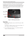
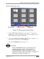
Weather Station
Operation/Installation Manual
Part Number A3280
Rev. 1.2
© Copyright Topcon Precision Agriculture
March, 2008
All contents in this manual are copyrighted by Topcon. All rights
reserved. The information contained herein may not be used, accessed,
copied, stored, displayed, sold, modified, published or distributed, or
otherwise reproduced without express written consent from Topcon.
Weather Station Operation/Installation Manual
Table of Contents
Preface............................................................................ 1-1
Terms & Conditions..................................................................... 1-2
Manual Conventions.................................................................... 1-8
Chapter 2
Disclaimer....................................................................... 2-1
Chapter 3
Introduction..................................................................... 3-1
Chapter 4
Using this Manual........................................................... 4-1
Chapter 5
Unpacking the Box......................................................... 5-1
Chapter 6
Installing the Weather Station Hardware...................... 6-1
Choosing a Mounting Location........................................................... 6-1
Mounting the Topcon Weather Station................................................ 6-2
Chapter 7
Installing the Weather Station Software....................... 7-1
Installing the Weather Station Software with X20 Guidance version
4.46.0.0 and earlier ............................................................................. 7-1
Upgrading ........................................................................................... 7-2
Changing Drive Letter.................................................................. 7-4
Chapter 8
Registering the Weather Station Software................... 8-1
A3280 Rev 1.2
i
Weather Station Operation/Installation Manual
Chapter 9
Setting Up the Weather Station Software..................... 9-1
Enabling the Weather Station............................................................... 9-2
Enabling the Weather Station Warnings............................................... 9-2
Units............................................................................................. 9-3
Setting the Weather Station Warning Alarm Points...................... 9-3
Number Of Repeats and Repeat Time.......................................... 9-4
Setting the Number of Repeats.............................................. 9-4
Setting the Repeat Time........................................................ 9-5
Chapter 10
Using the Weather Station Software........................... 10-1
Enabling the Guidance Status Bar..................................................... 10-1
Moving Compass............................................................................... 10-2
Wind Direction........................................................................... 10-2
Recording the Weather Station Data.................................................. 10-2
Chapter 11
Operation of the Weather Station................................11-1
Wind Speed.........................................................................................11-1
Relative Humidity...............................................................................11-2
Delta T.................................................................................................11-2
Temperature........................................................................................11-2
Chapter 12
Troubleshooting........................................................... 12-1
Weather Icon...................................................................................... 12-2
Weather Station.................................................................................. 12-2
Wind Speed and Direction................................................................. 12-3
Chapter 13
Maintenance.................................................................. 13-1
ii
www.topconpa.com
Weather Station Operation/Installation Manual
Chapter 14
Specifications............................................................... 14-1
Technical............................................................................................ 14-1
Electrical............................................................................................ 14-2
Mechanical......................................................................................... 14-2
Environmental.................................................................................... 14-3
Chapter 15
Spare Parts List............................................................ 15-1
Index
A3280 Rev 1.2
iii
Weather Station Operation/Installation Manual
Notes:
iv
www.topconpa.com
Weather Station Operation/Installation Manual
Preface
This manual has been developed to provide you with information
necessary to operate and maintain this Topcon Precision Agriculture
(TPA) product. Proper service and use is important for the safe and
reliable operation of the product. The sections provided in this manual
include information necessary for the safe and correct operation, care,
and troubleshooting of this product. The benefits this product provides
can be greatly influenced by your knowledge of the products described
in this manual.
NOTICE
Please read these Terms and Conditions carefully.
Terms and Conditions
General
APPLICATION - You accept these Terms and Conditions by
purchasing the product from Topcon Precision Agriculture (TPA)
or from one of TPA’s product dealers.
COPYRIGHT - All information contained in this manual is the
intellectual property of, and copyrighted material of TPA. All
rights are reserved. You may not use, access, copy, store, display,
create derivative works of, sell, modify, publish, distribute, or allow any third parties access to, any graphics, content, information
or data in this manual without TPA’s express written consent and
may only use such information for the care and operation of your
product. The information and data in this manual are a valuable
asset of TPA and are developed by the expenditure of
considerable work, time and money, and are the result or original
selection, coordination and arrangement by TPA.
A3280 Rev 1.2
1-1
Weather Station Operation/Installation Manual
TRADEMARKS – ZYNX, PROSTEER, EAGLE, KEE Technologies, Topcon, Topcon Positioning Systems and Topcon Precision Agriculture are trademarks or registered trademarks of the
Topcon Group of companies. Microsoft and Windows are trademarks or registered trademarks in the United States and/or other
countries of Microsoft Corporation. Product and company names
mentioned herein may be trademarks of their respective owners.
WEBSITE and OTHER STATEMENTS - No statement contained at the website of TPA or any other Topcon Group company
or in any other advertisements or TPA literature or made by an
employee or independent contractor of TPA modifies these Terms
and Conditions (Including the software licence, warranty and
limitation of liability).
IMPORTANT: SAFETY - Improper use of the product can lead
to death or injury to persons, damage to property and/or malfunction of the product. The product should only be repaired by
authorized TPA service centres. You should closely review the
safety warnings and directions as to the proper use of the product
in this manual and at all times comply with the same.
Limited Warranty
Electronic and Mechanical Components -TPA
warrants that the electronic components manufactured by TPA
shall be free of defects in materials and workmanship for a period
of one year from the original date of shipment to the dealer. TPA
warrants that all valves, hoses, cables and mechanical parts manufactured by TPA shall be free of defects in materials and workmanship for a period of 12 months from the date of sale.
Return and Repair - During the respective warranty periods, any of the above items found defective may be shipped to
TPA for repair. TPA will promptly repair the defective item at no
charge, and ship it back to you. You must pay the shipping and
1-2
www.topconpa.com
Weather Station Operation/Installation Manual
handling charges in respect of the same. Calibration or components, labour and travel expenses incurred for in-field removal
and replacement of components are not covered in this warranty
policy. Damage to components due to negligence, abuse or improper use, maintenance, modification or repair is NOT covered
under this warranty. Warranty is parts only; no labor or travelling
time will be covered.
Warranty Disclaimer - Other than for the above warranties or warranties in an appendix or a warranty card accompanying the product, this manual and the product are provided ‘as
is’. There are no other warranties and to the extent allowed by
law TPA excludes all implied terms, conditions and warranties
in respect of the manual and the product (including any implied
warranty or merchantability or fitness for any particular use or
purpose).
Liability Limit and Indemnity - TPA and its dealers,
agents and representatives shall not be liable for technical or editorial errors or omissions contained herein or for special, indirect,
economic, incidental or consequential damages resulting from
the furnishing, performance or use of this material or the product
(including where TPA has been advised of the possibility of such
damage). Such disclaimed damages include but are not limited to
loss of time, loss or destruction of data, loss of profit, savings or
revenue or loss of or damage to the product. In addition, TPA is
not responsible or liable for damages or costs incurred in connection with obtaining substitute products or software, claims by
others, inconvenience, or any other costs.
In any event, TPA’s liability to you or any other person for any
claim, loss or damage (in contract, tort or on any other basis) will
be limited (in TPA’s option) to either (a) the replacement or repair
of the product, or (b) payment of the cost of replacing or repairing the product. You indemnify and hold TPA harmless against
any claim, action, damage, loss, liability or cost (including legal
fees) which TPA incurs arising from (a) your operation, use and/
A3280 Rev 1.2
1-3
Weather Station Operation/Installation Manual
or maintenance of the product other that in accordance with the
terms set out in this manual, or (b) your negligence or wrongful
act or omission in respect of the product.
Other
These Terms and Conditions may be amended, modified, superseded or cancelled, at any time by TPA. These Terms and Conditions will be governed by, and construed in accordance with:
- the laws of South Australia if the product is sold and supplied
to you in Australia (in which case the courts of South Australia or
the Federal Court of Australia (Adelaide Registry) have exclusive
jurisdiction in respect of any claim or dispute); or
- the laws of the State of California if the product is sold and supplied to you outside of Australia.
All information, illustrations, and applications contained herein
are based on the latest available information at the time of publication. TPA reserves the right to make product changes at any
time without notice.
If any part of these Terms and Conditions would be unenforceable, the provision must be read down to the extent necessary
to avoid that result, and if the provision cannot be read down to
that extent, it must be severed without affecting the validity and
enforceability of the remainder of these Terms and Conditions.
1-4
www.topconpa.com
Weather Station Operation/Installation Manual
Comments, suggestions, and questions about TPA products are
welcomed. Contact your local TPA representative or a representative at our corporate facility.
Topcon Precision Agriculture
14 Park Way
Mawson Lakes, South Australia 5095.
Phone: +61 8 8203 3300
Fax: +61 8 8203 3399
Service Information
Service assistance can be provided by contacting your local TPA
Authorised Dealer or by calling the Topcon Precision Agriculture
Service Centre.
Phone:+61 8 8203 3300
Fax: +61 8 8203 3399
8.30am to 5pm (Adelaide Local Time), Monday through Friday.
A3280 Rev 1.2
1-5
Weather Station Operation/Installation Manual
Communications Regulation Information
FCC Compliance Statement (USA)
This equipment has been tested and found to comply with the limits for
a Class ‘A’ digital device, pursuant to Part 15 of the FCC Rules. Operation of this equipment in a residential area is likely to cause harmful interference in which case the user will be required to correct the
interference at their own expense.
FCC Compliance Statement (Canada)
This Class A digital apparatus meets all requirements of the Canadian
Interference-Causing Equipment Regulation.
‘C’ Tick EMC Statement (Australia & New Zealand)
Certification No. N12317. This product meets the applicable requirements of the Australia and New Zealand EMC Framework.
Radio & Television Interference
This computer equipment generates, uses, and can radiate radio-frequency energy. If it is not installed and used correctly – that is, in strict
accordance with TOPCON Precision Agriculture instructions – it may
cause interference with radio communication.
You can determine whether your computer system is causing interference by turning it off. If the interference stops, it was probably caused
by the computer or one of the peripheral electronic devices.
1-6
www.topconpa.com
Weather Station Operation/Installation Manual
If your computer system does cause interference to a radio or other
electronic device, try to correct the interference by using one or more of
the following measures:
•
•
•
•
Turn the radio antenna until the interference stops.
Move the computer to either side of the radio or other
electronic device.
Move the computer farther away from the radio or other
electronic device.
Connect the computer to a different circuit to the radio or other electronic device.
If necessary contact your nearest TOPCON Precision Agriculture dealer
for assistance.
Important: Changes or modifications to this product not authorized by
TOPCON Precision Agriculture could void the EMC compliance and
negate your authority to operate the product.
This product was tested for EMC compliance under conditions that
included the use of TOPCON Precision Agriculture peripheral devices
& TOPCON Precision Agriculture shielded cables and connectors between system components.
It is important that you use TOPCON Precision Agriculture peripheral
devices between system components to reduce the possibility of causing interference to radios and other electronic devices.
A3280 Rev 1.2
1-7
Weather Station Operation/Installation Manual
Manual Conventions
This Manual uses the following conventions:
File>Exit ~ Click/tap/press the File menu, then click/tap/press Exit.
Enter
~ Click/tap/press the button or key labelled Enter.
Supplementary information that can help you configure, maintain, or set up a system.
Supplementary information that can have an effect on system operation, system performance, measurements & personal safety.
Notification that an action has the potential to adversely effect system operation, system performance, data integrity, or personal health.
Notification that an action will result in systems damage, loss of data, loss of warranty, or personal injury.
UNDER NO CIRCUMSTANCES SHOULD THIS ACTION BE PERFORMED.
1-8
www.topconpa.com
Weather Station Operation/Installation Manual
Disclaimer
NOTICE
Please read this information carefully.
The weather measurements shown on the X20 console are being
obtained in conditions that are not in accordance with the normal
conditions required for true measurement of weather information,
as the sensors in the Weather Station may be effected by outside
variables such as sunlight, its intensity, reflective surfaces, dust
and pollutants such as diesel exhaust.
Weather measurements could differ from those taken in
accordance to standard accepted methods of measuring weather
data and should only be used as a guide. Humidity and the
Delta T calculation should not be relied upon if used to meet
product specifications.
If a true measurement is required this should be obtained by using
a calibrated scientific grade instrument, in accordance with the
instructions for that instrument.
A3280 Rev 1.2
2-1
Weather Station Operation/Installation Manual
Notes:
2-2
www.topconpa.com
Weather Station Operation/Installation Manual
Introduction
Congratulations on your purchase of the Topcon Weather Station. It has
been designed and built to the highest standards for years of reliable,
dependable and accurate service.
The Topcon Weather Station is designed to operate within the harsh
demands of the agricultural industry. However, no piece of electronic
equipment can function properly unless installed and maintained in the
correct manner. Please read carefully and follow these instructions for
installation and usage of the Topcon Weather Station, in order to ensure
optimal performance.
The Topcon Weather Station has the following features:
• Ultrasonic Wind Sensor
• Relative Humidity Sensor
• Temperature Sensor
• Waterproof Enclosure and Cable System
The Weather Station is connected to the X20 console’s CAN Bus Port.
The Weather Station information is displayed on the X20 Guidance
screen and displays the status of the temperature, relative humidity,
wind speed, and Delta T on the Guidance Status Bar.
The wind direction is displayed on the compass watermark on the
Guidance Coverage Map screen.
Audible alarms are also displayed on the X20 console, alerting the
operator of any alarm conditions.
A3280 Rev 1.2
3-1
Weather Station Operation/Installation Manual
The Weather Station information is automatically saved with the
Guidance Coverage Map file.
The Weather Station information can be viewed and printed with GDX
Viewer software on the X20 console or Desktop PC. The relative
humidity, temperature, wind speed, wind direction, Delta T maps, for
the field covered can be viewed or printed individually using GDX
Viewer. GDX Viewer can also print the weather data log with the
Coverage Map showing all the weather data points for the field, the log
printout shows each weather data point showing the following
information:
• Weather Data Point number
• Date and time of the weather point
• GPS location
• Wind speed
• Wind direction
• Temperature
• Relative Humidity
• Delta T
3-2
www.topconpa.com
Weather Station Operation/Installation Manual
Using this Manual
This manual is laid out as a simple to use, step-by-step guide to ensure
a trouble free, successful installation.
Follow, complete and confirm each step before moving to the next.
WARNING
Read and understand all the detail before
making any connections.
For troubleshooting please refer to the information in Chapter 12.
This manual will take the operator through the following steps:
• Unpacking the box, see Chapter 5
• Installing the Weather Station hardware, see Chapter 6
• Installing the Weather Station software from the USB Thumb
drive, see Chapter 7
• Registering the Weather Station software, see Chapter 8
• Setting up the Weather Station software, see Chapter 9
• Using the Weather Station software, see Chapter 10
A3280 Rev 1.2
4-1
Weather Station Operation/Installation Manual
Notes:
4-2
www.topconpa.com
Weather Station Operation/Installation Manual
Unpacking the Box
Topcon Precision Agriculture supplies all the basic equipment to mount
and operate the Topcon Weather Station onto most vehicles.
Contents of the Topcon Weather Station kit include the following:
Figure 5-1. Weather Station Kit
A3280 Rev 1.2
5-1
Weather Station Operation/Installation Manual
Figure 5-2. In Cab Weather Station Layout
5-2
www.topconpa.com
Weather Station Operation/Installation Manual
Figure 5-3. Outside Cab Weather Station Layout
A3280 Rev 1.2
5-3
Weather Station Operation/Installation Manual
Notes:
5-4
www.topconpa.com
Weather Station Operation/Installation Manual
Installing the Weather
Station Hardware
WARNING
Before installing the Weather Station ensure the
following have been checked and completed.
• Ensure the X20 console is already installed in the vehicle
• Ensure that you understand the X20 console Operator’s Manual
•
Before installing the Weather Station check the X20 console’s
serial number is A2010060472 or above. If the X20 console’s
serial number is below A2010060472 then it will need to be
returned to Topcon Precision Agriculture to be refined, so that it is compatible with the Weather Station.
Choosing a Mounting Location
Selecting a suitable mounting location is important for the optimal
performance of the Weather Station. The mounting location and
orientation of the Weather Station should be:
• On a flat surface, this gives the Wind/Weather sensor the best accuracy of wind speed and direction
•
High enough to have a clear view of the sky to the horizon, in all directions, unblocked by GPS antennas, and other
obstructions mounted on the roof of the vehicle. The Weather Station provides the best readings when wind
travelling through it is unimpeded by any obstructions.
A3280 Rev 1.2
6-1
Weather Station Operation/Installation Manual
WARNING
Do not mount the Weather Station near any heat
producing objects, like exhaust pipes.
TIP
Place the Dash Warning sticker (Figure 5-1 on page
5-1) in the operator of the vehicle’s line of vision, to
remind the operator of high mounted objects on the
vehicles roof.
Mounting the Topcon Weather Station
1. Find a suitable flat surface on the vehicle’s cabin
2. If attaching the Marine Mount (B125) to a plastic or fibre-glass
surface, then attach a metal plate, no smaller than 12”x 12”
(300mm x 300mm) to the plastic or fibre-glass surface. Then
attach the Marine Mount to the metal plate
TIP
When installing the Marine Mount, ensure that the
handle is in a convenient position to fold away the
Weather Station.
TIP
Ensure that when the Marine Mount is folded, it is not
obstructed by other equipment such as antennae or
rotating beacons etc.
3. Fix the Marine Mount (B125) to the flat metal surface using the 4 screws (F374), 4 flat washers (F200) and 4 nyloc nuts (F372) which are provided in the kit (Figure 5-3 on page 5-3)
6-2
www.topconpa.com
Weather Station Operation/Installation Manual
Screw the 3/4” (19mm) Threaded Socket (2302030) (Figure 5-3 on page 5-3) tightly to the Marine Mount
4. Screw the Mounting Pole (M247) (Figure 5-3 on page 5-3)
(with the outlet for the harness towards the Marine mount), to
the Threaded Socket (Figure 5-3 on page 5-3)
5. Route the Weather Station Power/Data Harness 26 ft
(8 metres) (A3372) (Figure 5-2 on page 5-2), through the outlet
on the pole (Figure 5-3 on page 5-3)
6. The In Line Terminator (Y943) is already connected to the
A3372 harness (Figure 5-3 on page 5-3)
7. Screw the 3/4” (19mm) Back nut (2052030) onto the pole (Figure
5-3 on page 5-3), screw the nut to the bottom of the pole thread
8. Screw the Weather Station Pole Mount Base onto the pole
(Figure 5-3 on page 5-3)
TIP
Do not screw the Weather Station Pole Mount base
all the way down (leave a few threads), to allow the
Weather Station to be fitted in the right direction.
The Pole Mount Base has three small holes for mounting screws and one larger hole for the humidity sensor.
9. Screw the In Line Terminator (Y943) to the connector at base of
the Weather Station (Figure 5-3 on page 5-3)
10. Place the Weather Station down on the Pole Mount Base and
attach the Weather Station to the Pole Mount using the
included brass mounting screws and lock washers (Figure 5-3
on page 5-3)
A3280 Rev 1.2
6-3
Weather Station Operation/Installation Manual
11. Ensure that the Pole Mount is orientated with the direction
arrow sticker (on top of the Weather Station) pointing in the
vehicle’s direction of travel
NOTICE
Aligning the mounting screw (nearest humidity
sensor) is important, as it will ensure that the correct
wind direction is displayed on the X20 console.
The direction arrow sticker is an indication only.
12. Screw the Back Nut (Figure 5-3 on page 5-3) up tight to lock in
the position of the Weather Station sensor
13. Route the A3372 harness (Figure 5-2 on page 5-2), along the
roof of the cabin and enter the inside of the cabin through
vehicle approved Gromets
14. Fix the harness to the roof using the 5 self adhesive back clips
(Y957) provided
15. Route the harness inside the cabin to where the X20 console is
installed
16. Connect the 9 pin connector of the A3372 harness to the CAN
Bus Port (Figure 2-4 on page 2-9 of the X20 console manual) at
the back of the X20 console
17. Connect the 2 Pin Weatherpack connector on the A3372
harness to the X20 console’s Switched Power connector on the
X20’s Power harness
6-4
www.topconpa.com
Weather Station Operation/Installation Manual
19. The A1953 (Figure 5-1 on page 5-1) may be required if the X20
console’s switched power connector is already used. This
provides 12 Volts to the Weather Station when the X20 console
is switched ON
20. Use the cable ties (Y216) provided, to keep the harness out of
the way. Do not cable tie the A3372 harness too tightly
21. Make sure the Weather Station Dash Label (W156) is on the
dashboard of the vehicle the Weather Station is attached to
(in the operator’s line of vision), to alert the operator that the
Weather Station is mounted on the vehicle’s roof.
This completes the hardware installation of the Weather Station.
A3280 Rev 1.2
6-5
Weather Station Operation/Installation Manual
Notes:
6-6
www.topconpa.com
Weather Station Operation/Installation Manual
Installing the Weather
Station Software
NOTICE
Please note that the Weather Station drivers have
been preinstalled on all X20 consoles manufactured
after November 2007.
To check whether the Weather Station software
needs to be installed check the X20 Guidance
software version. If the X20 Guidance software
version is 4.45.105S (October 2007) or later then
there is NO need to install the software loaded on the
USB Thumbdrive which come in the Weather Station
kit.
To check the X20 Guidance software version read
Chapter 4 “Guidance General Setup” in the
X20 Guidance Reference manual.
Software version 4.45.105S or later go to Chapter
8-1.
Software version 4.45.105S or earlier continue with
Chapter 7-1.
Installing the Weather Station software with
X20 Guidance version 4.46.0.0 and earlier
This section will explain how to install the Weather Station software
onto the X20 console.
The Weather Station software is located on the Thumbdrive (Figure 5-1
on page 5-1) which is part of the Weather Station kit.
A3280 Rev 1.2
7-1
Weather Station Operation/Installation Manual
A certain level of familiarity with the X20 console and the Windows
Operating System is assumed. If you have any trouble during the
installation please refer to any other relevant documentation provided
with the hardware, including all relevant manuals and guides. If you
require further assistance over and above this documentation, please
contact your dealer.
USB
Memory Slots
Power Plug
Power
Button
CAN Bus Port
Figure 7-1. X20 Console: Rear View
Upgrading
1. Plug the USB Thumbdrive into one of the X20 console’s USB
Memory slots
The X20 has 2 USB slots on the rear of the console (Figure 7-1)
and 2 USB slots on the side of the console.
2. Press the Power button (Figure 7-1), on the back of the X20
console, to switch the console on
7-2
www.topconpa.com
Weather Station Operation/Installation Manual
Guidance/ Steer Assist screen
STOP button
UPGRADE button
Progress Bar
Figure 7-2. X20 Product Selection Screen
3. On the X20 Product Selection screen (Figure 7-2) press the STOP button, before the Progress Bar moves completely to the right (which takes about 4-5 seconds)
4. Select the GUIDANCE/STEER ASSIST screen (Figure 7-2) and ensure it is the only screen highlighted
5. Press the UPGRADE button (Figure 7-2).
NOTICE
If the UPGRADE button is selected and a
window appears saying “Cannot find D:\
UPGRADE.EXE”, then select OK to close
window and then follow the steps on page 7-4;
otherwise continue to page 7-5.
A3280 Rev 1.2
7-3
Weather Station Operation/Installation Manual
Press here
Figure 7-3.About Product Selection Screen
Changing Drive Letter
Only follow the steps listed on this page if the message “Cannot
find D:\UPGRADE.EXE” appeared when you pressed the
UPGRADE button. If this message did not appear please continue
on page 7-5.
1. Press on the screen between SprayRate Controller and Boom
Leveler (Figure 7-3).
2. In the Upgrading From Drive window select a drive (D:, E:, F:,
or G:), by default “D:” is selected, if “D:” does not work
then select another drive letter.
7-4
If none of the drive letters work, then close the window and return to the Windows desktop, and double click on the My Computer icon, see what drive letter Windows has assigned the Thumbdrive, then contact Topcon Precision Agriculture.
www.topconpa.com
Weather Station Operation/Installation Manual
Figure 7-4.Start Upgrade Button
6. To proceed with the upgrade of the X20 console, select the Start Upgrade button (Figure 7-4)
Figure 7-5. Confirm Folder Replace Window
7. On the Confirm Folder Replace dialog box select the Yes to All button (Figure 7-5)
A3280 Rev 1.2
7-5
Weather Station Operation/Installation Manual
Figure 7-6. Files being Copied
The files will be copied from the USB Thumbdrive to the X20 console.
Once the files have been copied to the X20 console the X20 console
will automatically continue to load the X20 software programs that are
highlighted in the X20 Product Selection screen.
The upgrade is complete. The Guidance screen will be displayed. The
USB Thumbdrive can be removed from the console.
7-6
www.topconpa.com
Weather Station Operation/Installation Manual
Registering the Weather
Station Software
This section will show how to register the Weather Station software on
the X20 console:
1. Power the X20 Console ON, (if the console is not already ON)
2. At the X20 Product Selection screen ensure “Guidance/Steer Assist” is selected. The Guidance screen will be displayed (Figure
8-1)
Figure 8-1. Guidance Screen
3. On the Guidance screen press the EXIT/OFF button (Figure 8-1)
A3280 Rev 1.2
8-1
Weather Station Operation/Installation Manual
Figure 8-2. Register button
4. On the window that is displayed press the Register button
(Figure 8-2)
Figure 8-3. Register Applications
5. On the Register Applications dialog box select the Register
Weather Station button (Figure 8-3)
8-2
www.topconpa.com
Weather Station Operation/Installation Manual
Figure 8-4. Register Weather Station
6. On the Register Weather Station dialog box you need to enter a
password. Contact Topcon Precision Agriculture to receive the
password to register the software
Figure 8-5. WEATHER Button with
Guidance Startup Buttons
7. When the Weather Station software has been successfully registered
a WEATHER button will appear with the Guidance Startup
buttons (Figure 8-5).
A3280 Rev 1.2
8-3
Weather Station Operation/Installation Manual
Notes:
8-4
www.topconpa.com
Weather Station Operation/Installation Manual
Setting Up the Weather Station Software
Guidance Status Bar
Figure 9-1. WEATHER Button with
Guidance Startup Buttons
This section will show how to enable the Weather Station and setup the
Weather Station alarms.
1. Press the WEATHER button (Figure 9-1)
.
Figure 9-2. Weather Station Setup Window
A3280 Rev 1.2
9-1
Weather Station Operation/Installation Manual
Enabling the Weather Station
1. On the Weather Station Setup dialog box (Figure 9-2 on page
9-1) select the Weather Stn Enabled option, to enable the
Weather Station. To enable the Weather Stn option press the
white box (so that a black tick appears in it).
Enabling the Weather Station option allows the Weather Station
data:
• To display wind speed, temperature, humidity and Delta T on the Guidance status bar
• To display the wind direction on the Guidance Compass
watermark
• To be recorded every minute in the Guidance GDX file, so the data can be displayed in GDX Viewer at a later stage
NOTICE
Select the Weather Stn. Enabled option when the
Weather Station is connected to the X20 console.
Enabling the Weather Station Warnings
When the Weather Station warnings are enabled, audible warnings will
be sounded when a warning condition has been reached.
To enable the Weather Station warnings select the Warnings Enabled
option on the Weather Station Setup dialog box (Figure 9-2 on page
9-1), by pressing the white box (so that a black tick appears in it).
When the Weather Station Enabled option has been selected, then the
warnings will be sounded when the alarm points have been reached, as
displayed in the Warnings window (Figure 9-2 on page 9-1).
9-2
www.topconpa.com
Weather Station Operation/Installation Manual
Units
The units displayed for wind speed and temperature are determined
by the units selected in the Guidance>General Setup/>Units
window (page 4-12 of the X20 Guidance Manual).
• If Imperial units is selected then Fahrenheit will be used for
temperature and ‘miles per hour’ (mph) will be used for wind speed
• If Metric units is selected then Celsius, will be used for
temperature and ‘kilometres per hour’ (km/h) will be used for wind speed.
Warning alarms points can be set for the following:
• High Delta T
• Low Delta T
• High wind speed (High Wind:)
• High temperature (High Temp:)
Setting the Weather Station Warning Alarm Points
1. In the Warnings window on the Weather Station Setup
dialog box (Figure 9-2 on page 9-1) press the button next to
the warning alarm that requires changing
2. Using the calculator screen, type in the new alarm point
value using the buttons
3. Press the Enter button
A3280 Rev 1.2
9-3
Weather Station Operation/Installation Manual
The calculator screen will be closed and the new value will be
displayed on the button.
Repeat this process for each alarm point warning that requires
changing.
Number of Repeats and Repeat Time
The Number (No.) of Repeats option will determine how many
times the warnings will be sounded, when an alarm point has been
reached.
The Repeat Time will determine how many seconds elapse between
warnings, when the alarm point has been reached.
Setting the Number of Repeats
1. In the Warnings window on the Weather Station Setup
dialog box (Figure 9-2 on page 9-1) press the button next to
the No. of Repeats
2. Using the calculator screen, type in the number of repeats
that you desire, using the buttons
3. Press the Enter button
The calculator screen will be closed and the new value will be
displayed on the button.
9-4
www.topconpa.com
Weather Station Operation/Installation Manual
Setting the Repeat Time
1. In the Warnings window on the Weather Station Setup
dialog box (Figure 9-2 on page 9-1) press the button next to
the Repeat Time
2. Using the calculator screen, type in the repeat time
(in seconds) that you desire between warnings, using the
buttons
3. Press the Enter button.
The calculator screen will be closed and the new value will be
displayed on the button.
A3280 Rev 1.2
9-5
Weather Station Operation/Installation Manual
Notes:
9-6
www.topconpa.com
Weather Station Operation/Installation Manual
Using the Weather Station Software
This section will explain the functions and how to use the Weather
Station software.
Guidance Status Bar
Moving
Compass
watermark
Wind
Direction
arrow
Figure 10-1. Weather Station Data
The Weather Station data is displayed on the Guidance Status bar and
Moving Compass watermark, any time the Weather Station software
is enabled and the Weather Station sensor is connected correctly to the
X20 console.
Guidance Status Bar
1. Press the Guidance Status Bar until the Weather Station data is
displayed (Figure 10-1).
A3280 Rev 1.2
10-1
Weather Station Operation/Installation Manual
The following weather data will be displayed on the Guidance Status
Bar:
•
WS — Displays actual wind speed in mph or kph (see ‘Units’,
page 9-3). The wind speed displayed is the actual wind speed. If
the vehicle is moving the Guidance software takes this into
account and calculates the vehicle’s GPS speed and heading
direction and displays the actual wind speed.
•
T — The temperature is displayed in Fahrenheit (F) or Celsius
(C) (see ‘Units’, page 9-3)
•
RH — The relative humidity (%) is displayed
•
DT — Delta T is displayed.
Moving Compass
When the vehicle is moving the Moving Compass is displayed on the
Guidance Coverage Map screen.
Wind Direction
The ‘red arrow’ on the Moving Compass indicates the wind
direction. Like wind speed the wind direction takes into account the
vehicle’s GPS heading to display the actual wind direction.
Recording the Weather Station Data
For the Guidance to record the weather data with the Guidance
Coverage Map the Weather Station software must be enabled (see
‘Enabling the Weather Station Software’, page 9-2).
When the Guidance is drawing the Coverage Map on the Guidance
screen, then once a minute the weather data is saved automatically with
the Coverage Map data, in the GDX file.
10-2
www.topconpa.com
Weather Station Operation/Installation Manual
The weather data is recorded every minute with the GPS position, wind
speed, wind direction, temperature, humidity and Delta T. This weather
data is saved with the Guidance Coverage Map, when the field is saved,
the Weather data log can also be printed using the GDX Viewer
software.
The weather data can then be displayed and printed using the GDX
Viewer software at any time (as explained in the X20 Guidance
Operator’s manual). The maps that can be viewed and /or printed are;
Wind Speed and Direction (shown in Figure 10-3), Temperature, Humidity and Delta-T.
The average Wind Speed, Wind direction, Temperature, Humidity and
Delta T are also displayed in the Weather Data Details window for
each map.
A legend is also displayed for each weather data map, (the Wind Speed
legend is shown in Figure 10-3).
Figure 10-2. Wind Speed and Direction data
displayed in the GDX Viewer software
A3280 Rev 1.2
10-3
Weather Station Operation/Installation Manual
Notes:
10-4
www.topconpa.com
Weather Station Operation/Installation Manual
Operation of the
Weather Station
Wind Speed
The wind speed measurement portion of the Weather Station consists
of three ultrasonic transducers spaced equally around a horizontallyaligned circle.
The wind speed is measured by measuring the time of flight of an
ultrasonic sound pulse, generated by one sensor and received by the
other two sensors. Each of the three sensors takes a turn at being the
transmitter, while the remaining two sensors receive the pulse.
Wind blowing in the direction of flight of a pulse increases the speed of
the pulse by the amount of the wind speed. Measuring the time of flight
in both directions between a given pair of transducers allows the speed
of sound to be cancelled out of the calculation, making the wind speed
computation independent of air temperature and relative humidity.
The ultrasonic transducers are robust, yet sensitive instruments. The
transducers themselves must be kept free of any coating, such as paint.
NOTICE
The Weather Station unit itself, especially the area
between the transducers, must be kept clean and free
of debris for maximum wind speed and direction
accuracy.
A3280 Rev 1.2
11-1
Weather Station Operation/Installation Manual
Relative Humidity
Relative Humidity is measured from the humidity sensor located on the
base of the sensor.
Delta T
Delta T is calculated by the X20 Guidance software, from the
temperature and relative humidity readings sent from the Weather
Station sensor.
Temperature
Temperature is measured using the 3 ultra-sonic sensors on the Weather
Station to measure the speed of sound. Speed of sound is affected by
temperature, therefore temperature is calculated by measuring the speed
of sound between the sensors.
TIP
For best results a slight flow of air is required to give
an accurate temperature reading.
11-2
www.topconpa.com
Weather Station Operation/Installation Manual
Troubleshooting
In general, as long as you follow the instructions provided in this
manual, you should have few problems with your Weather Station. This
chapter will help you diagnose and solve some common problems you
may encounter.
WARNING
There are no user-serviceable components
inside the Topcon Weather Station. Opening the
Weather Station will expose the sensitive
electronic components to adverse environmental
conditions that may render the unit inoperative.
Please do not open the Weather Station, as this
will void the warranty.
If service is required please return the
equipment to your Topcon Precision Agriculture
service location.
A3280 Rev 1.2
12-1
Weather Station Operation/Installation Manual
Weather Icon
Problem
WEATHER icon is not displayed on the Guidance Startup buttons.
Causes
Solutions
The Weather Station
Contact Topcon Precision Agriculture to
has not been
register the software.
registered.
Weather Station
Problem
‘Weather Station not found’ is displayed on the Guidance Status bar.
Causes
Solutions
The Weather Station
Check harness is connected to the X20
sensor is not connected CAN Bus port.
to the X20 console’s
CAN Bus port.
The Weather Station is Check harness is connected to the X20
not powered up
Switched Power plug.
correctly.
Harness connections
Check all harness connections are tight.
are not tight.
12-2
www.topconpa.com
Weather Station Operation/Installation Manual
Wind Speed and Direction
Problem
Incorrect wind speed and direction.
Causes
Solutions
The flow of the wind
Ensure that the flow of the wind into the
into the Weather
Weather Station sensor is not blocked by
Station sensor is
surrounding structures.
blocked by surrounding
structures.
The flow of the wind
Ensure that the flow of the wind into the
into the Weather
Weather Station sensor is unimpeded and
Station sensor is
that the unit is free of debris.
impeded and blocked
by debris.
The Weather Station
Ensure that the Weather Station is not
sensor is mounted
mounted near a heat producing source such
near a heat producing
as the tractor exhaust pipes.
source.
The directional arrow
Rotate Weather Station sensor so the
on the Weather Station directional arrow is pointing forward, in the
is not orientated
vehicles direction of travel.
correctly.
If these steps do not solve your problem, please contact your Topcon dealer.
A3280 Rev 1.2
12-3
Weather Station Operation/Installation Manual
Notes:
12-4
www.topconpa.com
Weather Station Operation/Installation Manual
Maintenance
Regular maintenance is important to ensure continued proper operation
of the Topcon Weather Station.
You should perform the following tasks frequently:
•
Clean the unit with a soft cloth
WARNING
Do not use chemical cleaners as they may
remove paint or markings or may corrode the
Weather Station enclosure or seals.
•
Any spiderwebs etc that may accumulate inside the open portion
of the Weather Station, between the sensors, may be cleaned out
with a water spray
•
Ensure that the unit is mounted securely and cannot be moved
relative to the mounting surface
•
If the unit is loose, tighten the mounting screws.
A3280 Rev 1.2
13-1
Weather Station Operation/Installation Manual
Notes:
13-2
www.topconpa.com
Weather Station Operation/Installation Manual
Specifications
Technical
Parameter
Wind Speed Range
Wind Speed Resolution
Wind Speed Accuracy
Wind Direction
Accuracy
Temperature Range
Value
Comment
1-115 mph
(1 to 185 km/h)
1 mph
(1 km/h)
+2%
Tilt + 30° from vertical
+3°
Tilt + 30° from vertical
-13°F to 131°F
(-25°C to 55°C)
Temperature Accuracy
+1°F(+1°C)
-13°F to 100°F
(-25°C to 38°C)
+1.5°F(+1.5°C) 100°F to 131°F
(38°C to 55°C)
Relative Humidity
0-99% RH
Range
Relative Humidity
Resolution
Relative Humidity
Accuracy
1% RH
+5% RH
0%-99% RH
* Specifications are subject to change without notice.
A3280 Rev 1.2
14-1
Weather Station Operation/Installation Manual
Electrical
Parameter
Operating Voltage
Power Consumption
Load Equivalence
Number (LEN)
Reverse Battery
Protection
Load Dump Protection
Value
9 to 16 Volts
<250mA
5
Yes
Yes
Comment
DC Voltage
Average Current Drain
NMEA 2000® Spec.
(1LEN = 50mA)
Indefinitely
Energy Rated per SAE
J1113
Mechanical
Parameter
Size
Weight
Mounting
Value
5.0” (127mm)
Diameter x 5”
(127mm) Tall
10oz (283g)
Pole
Comment
Including Mounting
Bracket
Including Mounting
Bracket
Fits 1” (25mm)
Standard Marine Mount
(14 threads per 1”)
* Specifications are subject to change without notice.
14-2
www.topconpa.com
Weather Station Operation/Installation Manual
Environmental
Parameter
IEC 60954 Classification
Degree of Protection
Operating Temperature
Storage Temperature
Relative Humidity
Vibration
Value
Exposed
IP67
-13°F(-25°C) to 131°F (55°C)
-40°F (-40°C) to 158°F(70°C)
93% RH @ 40° per IEC 60954-8.2
2-13.2HZ @ + 1mm, 13.2-100HZ
@ 7m/s2 per IEC 60945-8.7
Rain and Spray
12.5mm Nozzle @ 100 liters/min from
3m for 30min per IEC 60945-8.8
Ultraviolet B,A, Visible, and Infrared per
Solar Radiation IEC 60945-8.10
Corrosion (Salt Mist)
4 times 7 days @ 40°C, 95% RH after 2
hour Salt Spray per IEC 60945-812
Electromagnetic Emission Conducted, Radiated Emission per IEC
60945-9
Electromagnetic Immunity Conducted, Radiated, Supply and ESD
per IEC 60945-10
Safety Precautions
Dangerous Voltage, Electromagnetic
Radio Frequency per IEC 60945-12
* Specifications are subject to change without notice.
A3280 Rev 1.2
14-3
Weather Station Operation/Installation Manual
Notes:
14-4
www.topconpa.com
Weather Station Operation/Installation Manual
Spare Parts List
Part Number
Description
K083
Weather Station Sensor
A1953
Power Adaptor Splitter Harness
A3116
X20 Thumbdrive Upgrade
A3280
Weather Station Installation Manual
A3372
Weather Station Power Data Harness
Y943
In Line Termination Resistor
2052030
3/4” Backnut
2302030
3/4” Threaded Socket
B125
Marine Aerial Mount
M247
Weather Station Mounting Pole
Y957
Adhesive Back Wire Clip
A2680
X20 Guidance Manual
A3280 Rev 1.2
15-1
Weather Station Operation/Installation Manual
Notes:
15-2
www.topconpa.com
Weather Station Operation/Installation Manual
Index
Numerics
2052030 6-3
2302030 6-2
A
A1953 6-5
A3372 harness 6-4
About Product Selection Screen 7-4
Assistance 7-1
Moving Compass 10-2
Wind Direction 10-2
E
Equipment 5-1
Contents of KIT 5-1
Exit/Off button 8-1
F
Connecting 3-1
Contact Information 1-5
F200 6-2
F372 6-2
F374 6-2
Features 3-1
Relative Humidity Sensor 3-1
Temperature Sensor 3-1
Ultrasonic Wind Sensor 3-1
Waterproof Enclosure and Cable
System 3-1
D
G
Delta T 11-2
calculating 11-2
Disclaimer 2-1
measurement of weather information 2-1
Displaying 10-1
Guidance Status Bar 10-1
DT (Delta T) 10-2
RH (Relative Humidity) 10-2
T (Temperature) 10-2
WS (Wind Speed) 10-2
GDX Viewer 3-2
Guidance Startup buttons 8-3
Weather button 8-3, 9-1
B
B125 6-2
Back Nut 6-4
C
A3280 Rev 1.2
I
Information Display 3-1
compass 3-1
Delta T 3-1
Guidance Status Bar 3-1
humidity 3-1
temperature 3-1
Index
Weather Station Operation/Installation Manual
wind direction 3-1
wind speed 3-1
Installation 6-1
Hardware 6-1
3/4” (19mm) Back nut (2052030)
6-3
A1953 6-4
A3372 harness 6-3, 6-4
2 pin weatherpack connector
6-4
9 pin connector 6-4
back nut 6-4
Before 6-1
X20 console 6-1
brass mounting screws 6-3
CAN Bus Port 6-4
direction arrow sticker 6-4
flat washers (F200) 6-2
gromets 6-4
lock washers 6-3
marine mount (B125) 6-2
handle 6-2
nyloc nuts (F372) 6-2
pole mount base 6-3
orientation 6-4
three small holes 6-3
power/data harness (A3372) 6-3,
6-4
screws (F374) 6-2
self adhesive back clips (Y957)
6-4
threaded socket (2302030) 6-3
X20 console’s switched power
connector 6-4
Software 7-1
thumbdrive 7-1
Index
M
Maintenance 13-1
cleaning 13-1
warning 13-1
mounted unit 13-1
Mounting location 6-1
best readings 6-1
Height 6-1
surface 6-1
warning 6-2
Moving Compass 10-2
O
Operation 11-1
P
Pole Mount Base 6-3
Printing 3-2
Delta T 3-2
humidity 3-2
temperature 3-2
weather data log 3-2
Date and time of the weather
point 3-2
GPS location 3-2
Weather data point number 3-2
wind direction 3-2
wind speed 3-2
R
Recording 10-2
Registering 8-1
applications 8-2
password 8-3
success 8-3
Relative Humidity 11-2
www.topconpa.com
Weather Station Operation/Installation Manual
measuring 11-2
RH (Relative Humidity) 10-2
S
Saving 3-2
Service Information 1-5
Software 9-1
setting up 9-1
weather station setup window
9-1, 9-2
weather stn. enabled 9-2
using 10-1
Software Version 7-1
preinstalled 7-1
Spare Parts List 15-1
Specifications 14-1
electrical 14-2
environmental 14-3
mechanical 14-2
technical 14-1
T
T (Temperature) 10-2
Temperature 11-2
Terms and Conditions 1-1
Thumbdrive 7-1, 7-2, 7-6
Troubleshooting 12-1
warning 12-1
warranty 12-1
weather icon 12-2
weather station 12-2
wind direction 12-3
wind speed 12-3
U
Units 9-3
imperial 9-3
A3280 Rev 1.2
metric 9-3
Upgrade 7-3
cannot find 7-3
confirm folder replace 7-5
from drive 7-4
select a drive 7-4
start upgrade button 7-5
V
Viewing 3-2
Delta T 3-2
humidity 3-2
temperature 3-2
wind direction 3-2
wind speed 3-2
W
Warnings 9-2
alarms points 9-3
Delta T 9-3
high 9-3
low 9-3
setting 9-3
calculator screen 9-3
temperature 9-3
high 9-3
wind speed 9-3
high 9-3
no. of repeats 9-4
setting 9-4
calculator screen 9-4
repeat time 9-4
setting 9-5
calculator screen 9-5
units 9-3
imperial 9-3
Index
Weather Station Operation/Installation Manual
metric 9-3
warnings enabled 9-2
Weather button 8-3, 9-1
Weather Station data 9-2
displayed 9-2
recorded 9-2
Wind Direction, correct 6-4
Windows desktop 7-4
my computer 7-4
thumbdrive 7-4
Wind Speed 11-1
measuring 11-1
sensors 11-1
clean 11-1
WS (Wind Speed) 10-2
X
X20 Console 7-2
power button 7-2
power plug 7-2
switchiong on 7-2
USB memory slots 7-2
location 7-2
X20 Product Selection Screen 7-3
guidance/ steer assist screen 7-3
progress bar 7-3
stop button 7-3
upgrade button 7-3
Y
Y943 6-3
Y957 6-4
Index
www.topconpa.com