1
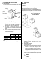
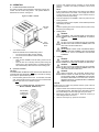
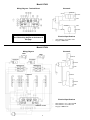
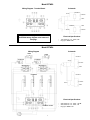
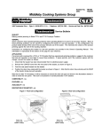
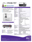
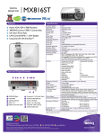
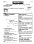
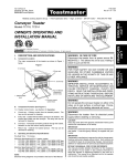
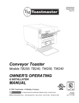
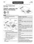
TP209/244/409/424/430; HT409/424; BTW09/24 English P/N 41491 Price $5.00 Rev. B V1 6/99 Middleby Cooking Systems Group 1400 Toastmaster Drive Elgin, IL 60120 (847)741-3300 FAX (847)741-4406 Solid State Slot Toaster Models TP209, TP224, TP409, TP424, TP430, HT409, HT424, BTW09, BTW24 OWNER'S OPERATING AND INSTALLATION MANUAL © 1999 Toastmaster, A Middleby Company. is a registered trademark of Toastmaster, A Middleby Company. All rights reserved. CAUTION Using any parts other than genuine Toastmaster factory parts relieves the manufacturer of all liability. WARNING: IN CASE OF FIRE Disconnect the toaster from its power source IMMEDIATELY. This allows the unit to cool, making it easier to put out the fire. IMPORTANT Contact your authorized service agent to perform maintenance and repairs. A service agency directory is supplied with your toaster. WARNING FOR YOUR SAFETY DO NOT STORE OR USE GASOLINE OR OTHER FLAMMABLE VAPORS OR LIQUIDS IN THE VICINITY OF THIS OR ANY OTHER APPLIANCE IMPORTANT Toastmaster (manufacturer) reserves the right to change specifications and product design without notice. Such revisions do not entitle the buyer to corresponding changes, improvements, additions or replacements for previously purchased equipment. WARNING IMPROPER INSTALLATION, ADJUSTMENT, ALTERATION, SERVICE OR MAINTENANCE CAN CAUSE PROPERTY DAMAGE, INJURY OR DEATH. READ THE INSTALLATION AND OPERATING INSTRUCTIONS THOROUGHLY BEFORE INSTALLING OR SERVICING THIS EQUIPMENT. RETAIN THIS MANUAL FOR FUTURE REFERENCE This manual provides detailed information for the installation and operation of your toaster. It also contains information to assist the operator in diagnosing problems in the event of a malfunction. This manual is an important tool for the operator and should be kept readily available. WARNING DO NOT PICK UP THE TOASTER BY INSERTING FINGERS INTO THE TOASTER SLOTS AND GRASPING THE HEATING ELEMENTS. ELECTRICAL SHOCK AND DAMAGE TO THE HEATING ELEMENTS CAN OCCUR. WARNING NEVER INSERT A KNIFE, FORK, OR SIMILAR OBJECT INTO THE TOASTING CHAMBER. ELECTRICAL SHOCK AND DAMAGE TO THE HEATING ELEMENTS CAN OCCUR. WARNING DISCONNECT THE UNIT FROM ITS ELECTRICAL POWER SUPPLY BEFORE CLEANING OR SERVICING. 1 I. DESCRIPTION AND SPECIFICATIONS II. INSTALLATION A. Component Location IMPORTANT IT IS THE CUSTOMERS RESPONSIBILITY TO REPORT ANY CONCEALED OR NON-CONCEALED DAMAGE TO THE FREIGHT COMPANY. The major components of the toaster are shown in Figure 1 below. Figure 1 A. 3b. Extra-wide, one-sided slot 3a. Standard slot Four-slot toasters (TP409/424/430, HT409/424, BTW09/24) may be installed EITHER on a countertop, OR on the four-slot toaster stand shown in Figure 2, below. The stand (Toastmaster P/N 1D3CS) is not included with your toaster, but is available separately. 4. Data plate (not shown at lower rear of toaster) 2. Operating lever Figure 2 - Four-slot toaster stand, Toastmaster P/N 1D3CS Available separately 1. Color selection knob 5. Removable crumb tray B. Installation Options and Kit Availability Two-slot toasters (TP209/224) are to be installed on a countertop, as described in Part B, Electrical Utility Connection, below. (model HT409/424 shown) Component Function (see Figure 1) 1. Color selection knob - see Section III, Operation. 2. Operating lever - see Section III, Operation. 3a. Standard slot - 1-1/8/29mm wide, these slots can accomodate Texas Size bread, frozen waffles, English muffins, etc. Heating elements are located on both sides of the slot. 3b. Extra-wide slot - 1-5/8/41mm wide, these slots can accomodate bagels and thick English muffins. A heating element is located on one side of the slot, permitting one-sided toasting. C. 4. Data plate - Provides manufacturing and electrical information. 5. Crumb tray - Collects crumbs from the toasted product. The tray can be removed for cleaning. Toaster Information Slot information: TP209, TP224 TP409, TP424, TP430 HT409, HT424 BTW09, BTW24 Standard slots 2 4 2 0 Extra-wide, one-sided slots 0 0 2 4 NOTE Electrical specifications are provided on the wiring diagrams at the back of this Manual. To install the toaster on a countertop, follow the instructions in Part B, Electrical Utility Connection, below. To install the toaster on a stand, follow the assembly instructions included with the stand kit. Then, proceed to Part B, Electrical Utility Connection. B. Electrical Utility Connection 1. Position the toaster in place. 2. Before proceeding with the electrical connection, check the following: a. Check that the electrical supply matches the toasters requirements. Refer to the toasters data plate (at the lower rear of toaster - see Figure 1), and to the electrical specifications provided on the wiring diagrams at the back of this Manual. b. Check that the appropriate receptacle is available for the power cord plug. c. Check that the main electrical supply source is turned OFF. CONSULT ALL APPLICABLE NATIONAL AND LOCAL CODES FOR FURTHER ELECTRICAL CONNECTION REQUIREMENTS. WARNING ENSURE THAT ANY PACKING MATERIAL RESIDUE HAS BEEN REMOVED FROM INSIDE THE TOASTING CHAMBER. 2 3. Insert the power cord plug into its receptacle. III. OPERATION A. 2. Location and Function of Controls This section provides a basic description of the toaster controls, their location, and the functions they perform. The operator MUST be familiar with the controls. See Figure 3. Turn the color selection knob (if necessary) to set the desired darkness. A medium color setting is achieved at the 9 oclock position. NOTE It will be necessary to determine the color setting for each different bakery product that is to be toasted. Test a single piece at the 9 oclock setting, and then adjust the Color Selection Knob as necessary to find the proper setting. Figure 3 -Toaster Controls 3. Press the Operating Lever DOWN to lower the product into the toasting chambers. 4. Wait for the toasting cycle to complete, and the toasted product will automatically be raised. OR Push the Operating Lever UP to manually raise the product at any time during the toasting cycle. C. Clearing Jams Operating Lever WARNING DISCONNECT THE TOASTER FROM ITS ELECTRICAL POWER SUPPLY BEFORE ATTEMPTING TO CLEAR A JAM. WARNING DO NOT TOUCH HOT SURFACES ON THE TOASTER, OR REACH INTO THE TOASTING CHAMBER, UNTIL THE UNIT HAS COOLED THOROUGHLY. Color Selection Knob 1. WARNING NEVER INSERT A KNIFE, FORK, OR SIMILAR OBJECT INTO THE TOASTING CHAMBER. THIS CAN CAUSE AN ELECTRICAL SHOCK OR DAMAGE THE HEATING ELEMENTS. Color Selection Knob Adjusts the darkness of the toasted bakery product. Turn the knob to the LEFT for lighter toasting. Turn the knob to the RIGHT for darker toasting. 2. B. D. Operating Lever Press the lever DOWN to load the bakery product into the toaster. Push the lever UP to manually raise the product during the toasting cycle. If the operating lever is not raised manually, it will be automatically raised at the end of the toasting cycle. WARNING DISCONNECT THE TOASTER FROM ITS ELECTRICAL POWER SUPPLY BEFORE CLEANING OR SERVICING. WARNING DO NOT TOUCH HOT SURFACES ON THE TOASTER, OR REACH INTO THE TOASTING CHAMBER, UNTIL THE UNIT HAS COOLED THOROUGHLY. Operation Procedure CAUTION THE REMOVABLE CRUMB TRAY MUST BE IN PLACE BEFORE THE TOASTER MAY BE OPERATED. If the tray is removed for cleaning, ensure that it is replaced before operation. 1. Cleaning WARNING WHEN CLEANING THE TOASTER, NEVER APPLY ENOUGH LIQUID TO STAND IN PLACE ON THE UNIT. DO NOT SPRAY, RINSE, OR SUBMERGE THE TOASTER. EXCESSIVE MOISTURE IN THE UNIT WILL CAUSE A SEVERE ELECTRICAL HAZARD AND MAY OTHERWISE DAMAGE THE TOASTER. Insert the bakery product into the slots. For extra-wide, one-sided slots, check that the side of the product that is to be toasted faces the LEFT side of the slot, as shown in Figure 4. CAUTION DO NOT clean your toaster using abrasive cleaners or pads. Both will scratch and dull the finish. Figure 4 - Loading extra-wide, one-sided slots Models HT409/424, BTW09/24 only Side of bakery product to be toasted faces LEFT 3 1. Wipe the exterior of the toaster with a sponge or cloth soaked in hot or warm detergent water. Wipe with a clean, damp cloth to remove the excess detergent, and then wipe again to dry the toaster. 2. Remove the crumb tray, and empty it. Wash the crumb tray in warm detergent water, and rinse it. 3. After the crumb tray is dry, replace it in the toaster. Model TP209 Wiring Diagram - Terminal Board ELEMENTS SWITCH SOLENOID TIMER NOTE: All other wiring connections match the TP224 wiring diagram at the bottom of this page. Electrical Specifications 120V, 50/60 Hz, 1 Ph, 1.1kW, 9.0A Plug type: NEMA 5-15P Model TP224 Wiring Diagram Schematic TIMER ELEMENTS SOLENOID SWITCH SOLENOID MICROSWITCH TIMER ELEMENTS Electrical Specifications TERMINAL BOARD 4 208V, 50/60 Hz, 1 Ph, 1.0kW, 4.8A OR 240V, 50/60 Hz, 1 Ph, 1.3kW, 5.3A Plug type: NEMA 6-15P Model TP409 Wiring Diagram - Terminal Board Schematic ELEMENTS SWITCH SOLENOID TIMER ELEMENTS TIMER SWITCH NOTE: All other wiring connections match the TP424/430 wiring diagram at the bottom of this page. SOLENOID Electrical Specifications 120V, 50/60 Hz, 1 Ph, 2.2kW, 18.3A Plug type: NEMA 5-20P (USA) OR NEMA 5-30P (Canada) Models TP424 & TP430 Schematic Wiring Diagram TIMER TIMER ELEMENTS SOLENOID SOLENOID SWITCH SOLENOID MICROSWITCH MICROSWITCH TIMER ELEMENTS ELEMENTS SOLENOID SWITCH TIMER Electrical Specifications TERMINAL BOARD Model TP424: 208V, 50/60 Hz, 1 Ph, 2.0kW, 9.6A OR 240V, 50/60 Hz, 1 Ph, 2.6kW, 10.8A Plug type: NEMA 6-15P Model TP430: 208V (Canada), 50/60 Hz, 1 Ph, 2.6kW, 12.5A Plug type: NEMA 6-20P 5 Model HT409 Wiring Diagram - Terminal Board Schematic ELEMENTS SWITCH SOLENOID TIMER ELEMENTS TIMER SWITCH NOTE: All other wiring connections match the HT424 wiring diagram at the bottom of this page. SOLENOID Electrical Specifications 120V, 50/60 Hz, 1 Ph, 2.0kW, 16.6A Plug type: NEMA 5-20P Model HT424 Schematic Wiring Diagram TIMER TIMER ELEMENTS SOLENOID SOLENOID SWITCH SOLENOID MICROSWITCH MICROSWITCH TIMER ELEMENTS ELEMENTS SOLENOID SWITCH TIMER Electrical Specifications TERMINAL BOARD 6 208V, 50/60 Hz, 1 Ph, 1.7kW, 8.0A OR 240V, 50/60 Hz, 1 Ph, 2.2kW, 9.2A Plug type: NEMA 6-15P Model BTW09 Wiring Diagram - Terminal Board Schematic ELEMENTS SWITCH SOLENOID TIMER ELEMENTS TIMER SWITCH NOTE: All other wiring connections match the BTW24 wiring diagram at the bottom of this page. SOLENOID Electrical Specifications 120V, 50/60 Hz, 1 Ph, 1.8kW,15.0A Plug type: NEMA 5-20P Model BTW24 Schematic Wiring Diagram TIMER TIMER ELEMENTS SOLENOID SOLENOID SWITCH SOLENOID MICROSWITCH MICROSWITCH TIMER ELEMENTS ELEMENTS SOLENOID SWITCH TIMER Electrical Specifications TERMINAL BOARD 7 208V, 50/60 Hz, 1 Ph, 1.6kW, 7.7A OR 240V, 50/60 Hz, 1 Ph, 1.8kW, 7.5A Plug type: NEMA 6-15P A Middleby Company Toastmaster 1400 Toastmaster Drive Elgin, IL 60120 USA (847)741-3300 FAX (847)741-4406 Middleby Corp 24-Hour Service Hotline 1-800-238-8444 www.middleby.com 8