1
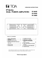
OPERATING INSTRUCTIONS
IP Series
DUAL POWER AMPLIFIERS
IP-600D
IP-450D
IP-300D
TABLE OF CONTENTS
1.
2.
3.
4.
5.
SAFETY PRECAUTIONS
GENERAL DESCRIPTION
FEATURES
HANDLING PRECAUTIONS
NOMENCLATURE AND FUNCTIONS
Front panel
Rear panel
6. INSTALLATION
7. CONNECTIONS
2
4
4
4
5
6
7
8
8. CLEANING THE FILTER
9. REMOVING THE HANDLE
10. INSTALLING AN OPTIONAL
MATCHING TRANSFORMER
LT-101
11. BLOCK DIAGRAM
12. TABLE FOR PROTECTION CIRCUIT
ACTIONS
13. APPEARANCE AND DIMENSIONS
14. SPECIFICATIONS
Please follow the instructions in this manual to obtain the optimum results from this unit.
We also recommend that you keep this manual handy for future reference.
TOA Corporation
9
9
10
10
11
11
12
1. SAFETY PRECAUTIONS
Be sure to read the instructions in this section carefully before use.
Make sure to observe the instructions in this manual as the conventions of safety symbols and messages
regarded as very important precautions are included.
We also recommend you keep this instruction manual handy for future reference.
Safety Symbol and Message Conventions
Safety symbols and messages described below are used in this manual to prevent bodily injury and property
damage which could result from mishandling. Before operating your product, read this manual first so you are
thoroughly aware of the potential safety hazards as well as understand the safety symbols and messages.
Indicates a potentially hazardous situation which, if mishandled,
could result in death or serious personal injury.
Indicates a potentially hazardous situation which, if mishandled,
could result in moderate or minor personal injury, and/or proper
damage.
When Installing the Unit
When the Unit is in Use
Do not expose the unit to rain or an environment
where it may be splashed by water or other
liquids, as doing so may result in fire or electric
shock.
To prevent a fire or electric shock, never open nor
remove the unit case as there are high voltage
components inside the unit. Refer all servicing to
your nearest TOA dealer.
Use the unit only with the voltage specified on the
unit. Using a voltage higher than that which is
specified may result in fire or electric shock.
Do not place cups, bowls, or other containers of
liquid or metallic objects on top of the unit. If they
accidentally spill into the unit, this may cause a fire
or electric shock.
Do not cut, kink, otherwise damage nor modify the
power supply cord. In addition, avoid using the
power cord in close proximity to heaters, and
never place heavy objects -- including the unit
itself -- on the power cord, as doing so may result
in fire or electric shock.
Do not insert nor drop metallic objects or
flammable materials in the ventilation slots of the
unit's cover, as this may result in fire or electric
shock.
Be sure to replace the unit's terminal cover after
connection completion. Because the voltage of up
to 100 V is applied to the output terminals, never
touch these terminals to avoid electric shock.
Avoid installing or mounting the unit in unstable
locations, such as on a rickety table or a slanted
surface. Doing so may result in the unit falling
down and causing personal injury and/or property
damage.
Install the unit only in a location that can
structurally support the weight of the unit and the
mounting bracket. Doing otherwise may result in
the unit falling down and causing personal injury
and/or property damage.
2
Do not touch a plug during thunder and lightning,
as this may result in electric shock.
Should the following irregularity be found during
use, immediately switch off the power, disconnect
the power supply plug from the AC outlet and
contact your nearest TOA dealer. Make no further
attempt to operate the unit in this condition as this
may cause fire or electric shock.
• If you detect smoke or a strange smell coming
from the unit.
• If water or any metallic object gets into the unit.
• If the unit falls, or the unit case breaks.
• If the power supply cord is damaged (exposure
of the core, disconnection, etc.)
• If it is malfunctioning (no tone sounds.)
When Installing the Unit
Never plug in nor remove the power supply plug
with wet hands, as doing so may cause electric
shock.
When unplugging the power supply cord, be sure
to grasp the power supply plug; never pull on the
cord itself. Operating the unit with a damaged
power supply cord may cause a fire or electric
shock.
When moving the unit, be sure to remove its power
supply cord from the wall outlet. Moving the unit
with the power cord connected to the outlet may
cause damage to the power cord, resulting in fire
or electric shock. When removing the power cord,
be sure to hold its plug to pull.
Do not block the ventilation slots in the unit's cover.
Doing so may cause heat to build up inside the
unit and result in fire.
Avoid installing the unit in humid or dusty locations,
in locations exposed to the direct sunlight, near
the heaters, or in locations generating sooty
smoke or steam as doing otherwise may result in
fire or electric shock.
When unpacking or moving the unit, be sure to
handle the unit with two or more persons. Falling
or dropping the unit may cause personal injury
and/or property damage.
RISK OF ELECTRIC SHOCK
DO NOT OPEN
TO REDUCE THE RISK OF ELECTRICAL
SHOCK, DO NOT REMOVE COVER. NO
USER SERVICEABLE PARTS INSIDE.
REFER SERVICING TO QUALIFIED
SERVICE PERSONNEL.
When the Unit is in Use
Do not place heavy objects on the unit as this may
cause it to fall or break which may result in
personal injury and/or property damage. In
addition, the object itself may fall off and cause
injury and/or damage.
Make sure that the volume control is set to
minimum position before power is switched on.
Loud noise produced at high volume when power
is switched on can impair hearing.
Do not operate the speaker for an extended period
of time with the sound distorting. This is an
indication of a malfunction, which in turn can
cause heat to generate and result in a fire.
Contact your TOA dealer as to the cleaning. If dust
is allowed to accumulate in the unit over a long
period of time, a fire or damage to the unit may
result.
If dust accumulates on the power supply plug or in
the wall AC outlet, a fire may result. Clean it
periodically. In addition, insert the plug in the wall
outlet securely.
Switch off the power, and unplug the power supply
plug from the AC outlet for safety purposes when
cleaning or leaving the unit unused for 10 days or
more. A fire or electric shock may result.
The lighting flash with arrowhead within a
triangle is intended to tell the user that
parts inside the product are a risk of
electric shock to persons.
The exclamation point within a triangle is
intended to tell the user that important
operating and servicing instructions are
in the papers with the appliance.
3
2. GENERAL DESCRIPTION
TOA's IP series dual power amplifiers feature high durability, high quality sound and high output power (IP300D: 300 W, IP-450D: 450 W, IP-600D: 600 W - when a 4 load connected). Input/output levels and other
functions can be remotely controlled from external equipment. (An interface unit is required. For details,
contact your TOA dealer.) The amplifier is ideal for use in store sound systems, permanently-installed sound
systems, and other sound systems.
3. FEATURES
Small in size (2-rack unit size) and light in weight.
Variable forced-air cooling system changes the speed of a fan as the heat sink temperature varies, keeping
fan operation noise low.
The input is an electrically-balanced input, which can be converted into a transformer-balanced input using
an optional input transformer.
Three different output modes are made available for selection: Stereo, BTL and parallel outputs. In parallel
mode, the input level of each channel can be set independently.
An internal limiter limits the current during overload, and a protection circuit disconnects the output during an
output short circuit by detecting the levels of both voltage and current. The protection circuit also
disconnects the output during an abnormal temperature rise.
Large output screw terminals (10 mm in width) allow connection of solderless terminals with diameter of 9.5
mm. Because two of each of positive (+) and negative (-) terminals are provided, even the four-core
speaker cables can be connected.
Control I/O terminal. Input and output levels can be remotely controlled or monitored from external
equipment. (An interface unit is required. For details, contact your TOA dealer.)
Detachable carrying handles even after the unit is installed in a rack.
A push-lock level control and its cover prevent accidental setting changes after installation.
An AC inlet simplifies the system maintenance after installation.
4. HANDLING PRECAUTIONS
Line Source: 120 VAC ± 10%, 60 Hz
Never connect the AC power cord to any other line voltage than that specifically designated.
To avoid oscillation, keep the input cable away from the output cable. Particular care must be exercised
when mounting the unit in an equipment rack.
In some installations, a ground loop is formed and such noise as hum may be generated. In such cases, cut
the loop by removing a shorting metal piece attached to the ground terminals on the rear panel. The noise
can be reduced.
These power amplifiers have a filter in their front panel. Clean the filter as frequently as possible. If it
becomes clogged, heat cannot escape from the inside of the unit.
Never connect two amplifier outputs in parallel under any circumstances.
4
5. NOMENCLATURE AND FUNCTIONS
[ Front Panel ]
Power switch
Power is switched on
depression of this switch.
Carrying handle
and off
with each
Can be detached. Refer to p.9 when removing.
Input level control (pushlock type)
Power indicator lamp
Lights green when the power is switched on.
Signal indicator lamp
Lights green regardless of the input level control setting
when there is an input of a signal with a level
exceeding -30 dB.
Peak indicator lamp
Clicks at each dB mark on the scale when rotated. This
knob is recessed to avoid accidental setting changes.
Pressing on the knob raises it above the front panel to
permit level adjustment.
[Precautions]
When the level control switch on the rear panel is set to
ON, the input level control cannot be used because it is
bypassed.
Lights red if an output signal clips (distortion occurs).
Protection circuit indicator lamp
Lights red for three seconds after the power is supplied
to the unit, and then goes out. This lamp also lights red
when a protection circuit is activated. Refer to p. 11
"Table for protection circuit actions" for details.
Level control bypass indicator lamp
Level control cover
An input level can be fixed by removing the input
level control knob from the front panel and
attaching the supplied control cover.
[Note]
Keep the removed input level control knob for
future use.
Lights yellow when the level control switch
(refer to
p.6) is in the ON position. While this lamp remains lit,
the input level control cannot be used because it is
bypassed.
5
[Rear panel]
Input terminal
Level control switch
Electrically-balanced input terminals. The 3P screw
terminal is connected in parallel with a balanced phone
jack.
Also, the input can be converted into a transformerbalanced input using an optional matching transformer
LT-101.
Usually, set this switch to OFF. When an interface unit
is connected, shifting this switch to ON permits external
input level adjustment.
3P screw terminal
H:HOT
C:COLD
[Precautions]
No sound is output if the level control switch is set to
ON without connecting an interface unit. Confirm the
switch position before switching on the power. Be sure
to switch off the power when changing control switch
settings.
E:GROUND
Control I/O terminal
Balanced phone jack
T (Tip): HOT R (Ring): COLD S(Sleeve): GROUND
Phone jack
Connects to the an interface unit when monitoring or
performing remote controls from external equipment.
For details, contact your TOA dealer.
Phone plug
[Precautions]
No other unit other than an interface unit must be
connected to the terminal. Be sure to switch off the
power when connecting an interface unit.
Output mode selector switch
Output terminal (with a protection cover)
Selects STEREO, BTL or PARALLEL mode.
Connect speaker cables to these terminals. Because
the upper terminals are connected in parallel with the
lower terminals, both terminals can be used
simultaneously. Refer to p.8 for speaker cable
connections.
STEREO mode
Channels 1 and 2 are operated independently. (The
unit functions as a normal stereo amplifier.) Channel
1 input signal goes to Channel 1 output, and
Channel 2 input signal goes to Channel 2 output.
BTL mode
The unit functions as a monaural amplifier with 1
input and 1 output. Channel 1 input signal goes to
both output BTL (+) and (-) terminals.
PARALLEL mode
The unit functions as a monaural amplifier with 1
input and 2 outputs. Channel 1 input signal goes to
the outputs of both Channels 1 and 2. Input signal
levels of channels 1 and 2 can be set independently.
[Precautions]
Be sure to switch off the power when connecting the
speaker cables. Never connect two amplifier outputs in
parallel under any circumstances.
Grounding terminal for signals
When the power amplifier is connected to other
equipment, grounding sometimes creates a loop,
producing hum noise. This loop can be cut and noise
reduced by removing a shorting metal piece connecting
two terminals.
AC inlet
[Precautions]
Use only Channel 1 input terminal when in BTL or
PARALLEL mode. Do not use Channel 2 input terminal.
Confirm the position of the output mode selector switch
before switching on the power. Be sure to switch off the
power when changing mode switch settings.
6
Rear mounting bracket
6. INSTALLATION
Carefully note heat radiation when installing the unit. These power amplifiers are equipped with a cooling
fan. To avoid heat buildup, ensure that the rear of the unit is at least 10 cm away from the wall surface.
When mounting the unit in the rack, the inside of the rack must be well ventilated. To accomplish this, keep
the rear side of rack open (no panel is mounted), and mount a ventilation panel of over 1-unit size in the
uppermost and lowermost rack positions on the rack front.
When installing in the rack, be sure to mount a perforated panel of over 1 -unit size between the amplifiers.
See the figure below.
Robust structure is one of the unit's main features. However, if the strength is particularly needed when
installing the unit in the rack, use the supporting runner YA-706 (option) for the safety purposes.
7
7. CONNECTIONS
1. Switch off the amplifier power.
2. Unscrew the output terminal cover.
3. Strip 10 mm of insulative jacket from the end of the speaker cable,
as shown in the figure at right.
4. Connect speaker cables to the output terminals.
5. Fit the output terminal cover in place.
[Precautions] Be sure to fit the output terminal cover in place.
Take care that the naked wires of the speaker lines do not contact the unit's chassis.
Refer to the figures below for connections for each output mode.
Since the upper output terminals are connected in parallel with the lower terminals, both terminals can be
used simultaneously.
Output mode switch
STEREO mode
Output terminal
BTL mode
Output mode switch
PARALLEL mode
Output mode switch
Output terminal
Output terminal
[Precautions]
The total impedance of the connected speakers must be over 4 (STEREO and PARALLEL modes) or over 8
(BTL mode). If the impedance of the connected speakers is smaller than those stated above, equipment failures
may result.
Refer to the table below when using an optional output transformer.
Power amplifier
IP-600D
IP-450D
IP-300D
Output transformer(option)
MT-600M
MT-450M
MT-300M
[Precautions]
Do not connect the output transformer under any circumstances when in BTL mode. Both the amplifier and
transformer may fail.
8
8. CLEANING THE FILTER
1. Switch off the amplifier power.
2. Pull the filter from the front panel as shown in the figure.
3. Clean the filter.
4. Fit the filter in place.
[Precautions] Make sure that the fan is turned off when removing the filter.
Filter
9. REMOVING THE HANDLE
1. Switch off the amplifier power.
2. Remove the handle cover.
3. Remove two screws holding the handle to the amplifier.
4. Remove the handle.
Handle
5. Install the supplied screws (M4x20).
Handle cover
6. Attach the handle cover to the unit.
Handle cover
9
10. INSTALLING AN OPTIONAL MATCHING TRANSFORMER LT-101
[ CAUTION ]
THESE SERVICING INSTRUCTIONS ARE FOR USE BY QUALIFIED PERSONNEL ONLY.
TO AVOID ELECTRIC SHOCK, DO NOT PERFORM ANY SERVICING OTHER THAN THAT
CONTAINED IN THE OPERATING INSTRUCTIONS UNLESS YOU ARE QUALIFIED TO DO SO.
REFER ALL SERVICING TO QUALIFIED SERVICE PERSONNEL.
1. Attach sleeves supplied with the transformer to the transformer.
2. Remove case fixing screws to remove the case.
3. When installing the transformer at channel 1, disconnect connector CN323 (with a lead) from CN324. Insert
CN323 into the transformer connector marked with IN, then insert the connector (with a lead) from the
transformer into CN324. When installing the transformer at channel 2, disconnect connector CN326 (with a
lead) from CN327. Insert CN326 into the transformer connector marked with IN, then insert the connector
(with a lead) from the transformer into CN327.
4. Mount the transformer to the rear panel.
5. Replace the case.
[Precautions] Make sure that the power is switched off when installing the transformer.
11. BLOCK DIAGRAM
10
12. TABLE FOR PROTECTION CIRCUIT ACTIONS
Symptom
Excessive current flow
due to overload
Action
Current limiter operates
when load resistance is
Remove overload.
)
(STEREO/PARALLEL) or
Unusual DC voltage output
Speaker loads cut by
output relay.
(BTL) load is
connected.
Check short circuit of
speakers and lines.
Switch power off, connect
correct load, and switch
power on.
Check ventilation and
overload.
temperature drops.
Protection circuit
Contact your TOA
indicator lights.
dealer.
Switch power off, then
remove cause.
Current limiter operates. Protection circuit
indicator lights.
Speaker loads cut by
output relay.
Heat sink temperature rise Speaker loads cut by
output relay.
Automatically reset if 4
8
under 2.5 (STEREO/
PARALLEL) or 5
(BTL).
Short circuit (under 0.5
Reset
Remedy
Indicator
Peak indicator lights.
Protection circuit
indicator lights.
Automatically reset if
13. APPEARANCE AND DIMENSIONS
Unit: mm
11
14. SPECIFICATIONS
Model No.
Output 20 Hz - 20 kHz
IP-300D
IP-450D
STEREO RL=4
300 W
450 W
600 W
RL=8
200 W
300 W
400 W
RL=8
600 W
900 W
1200 W
BTL
Frequency Response
Total Harmonic Distortion
8
, 1 kHz
8
, 20 Hz - 20 kHz
IP-600D
20 Hz - 20 kHz (+0 dB, -0.5 dB)
0.01%
0.1%
Intermodulation Distortion
0.03%
60 Hz : 7kHz= 4:1, 8
Input Sensitivity
+ 5.3 dB (1.42 V) ±0.5 dB
(8 , input level control in maximum position) + 2.2 dB (1.00 V) ±0.5 dB + 4.0 dB (1.23 V) ±0.5 dB
Voltage Gain
32 dB
Input Impedance
10 k (electrically-balanced)
110 dB (at 26 dB gain)
112 dB (at 26 dB gain)
Signal-to-Noise Ratio
108 dB (at 26 dB gain)
20 Hz - 20 kHz
103 dB (at 32 dB max. gain) 105 dB (at 32 dB max. gain) 107 dB (at 32 dB max. gain)
Cooling Fan Speed
Under 40 °C : Stop
40 °C-75 °C : Low to high speed (variable)
Over 75 °C : High speed
Input
(CH1
,
CH2)
: screw terminal, balanced phone jack
Connection Terminal
Output
: Terminal with screw/washer assembly
Indicator
Power Source
Power Consumption
Based on UL/CSA standards
Finish
Dimensions
Weight
CONTROL I/O
: 8P DIN
Power supply
: AC inlet
POWER (green), SIGNAL x 2 (green) , PEAKx2 (red) , PROTECT x 2 (red) , VR BYPASS x 2 (yellow)
120VAC±10%, 60 Hz
444 VA
648 VA
984 VA
Panel: Zinc diecasting, black paint
Case: Colored steel plate, black
482 (W) X 102.4 (H) X 473.5 (D) mm
13 kg
18 kg
[Notes]
0 dB=0.775 Vrms
The above specifications are subject to change without notice.
Accessories
Screw M4x20
Power cord (2.5 m)
Level control cover
Instruction manual
4
1
2
1
Printed in Japan
TOA Corporation
133-12-566-7A