1
Maintenance Manual
TravelMate 5000 Series
Notebook Computers
9786166-0001
March 1995
Copyright (©) 1995 Texas Instruments Incorporated
All Rights Reserved — Printed in U.S.A.
TravelMateTM 5000 Series Notebook Computers
Maintenance Manual
TI Part No. 9786166-0001
Original Issue: March 1995
Changes may be made periodically to the information in this publication.
Such changes will be incorporated in new editions of this manual.
Record the serial number, purchase date, and model number in the spaces
provided below. The serial number and model number are recorded on the
label affixed to the case. All correspondence concerning your unit should include the serial number, model number, and date of purchase.
No part of this publication may be reproduced, stored in a retrieval system,
or transmitted, in any form or by any means, electronic, mechanical,
photocopy, recording, or otherwise, without the prior written permission of
Texas Instruments Incorporated.
The equipment, as well as the programs that TI has created to use with
them, are tools that can help people better manage the information used in
their business; but tools — including TI products — cannot replace sound
judgement nor make the manager’s business decisions.
Consequently, TI cannot warrant that its products are suitable for any
specific customer application. The manager must rely on judgement of what
is best for his or her business.
Address all correspondence regarding orders to:
Texas Instruments Incorporated
P.O. Box 6102, M/S 3255
Temple, Texas 76503
TravelMate, 5000, 4000M, 4000E, 4000, and BatteryPro are trademarks of Texas
Instruments Incorporated. The icons in the Windows Notebook and Startup
groups are copyrighted by Texas Instruments Incorporated.
BitCom and BotFax are trademarks of BIT Software, Inc.
Hayes is a registered trademark and SmartModem2400 is a trademark of Hayes
Microcomputer Products Inc.
IBM, OS/2. AT. PS/2, and VGA are trademarks of International Business Machines
Corporation.
Intel, 386, and 387, and Pentium are trademarks of Intel Corporation.
Lotus is a trademark of Lotus Development Corporation.
MNP is a registered trademark and Microcom is a trademark of Microcom Inc.
Microsoft, GW-Basic, MS-DOS, BallPoint, QuickPort, and MS are registered trademarks and Windows, Xenix, and Excel are trademarks of Microsoft Corporation.
Ethernet is a registered trademark of Xerox Corporation
Paintbrush is a registered trademark of ZSoft Corporation
NetWare is a registered trademark of Novell, Inc.
UNIX is a registered trademark of American Telephone and Telegraph.
SimuSCAN is a trademark of Cirrus Logic, Inc.
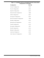
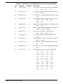
Contents
Preface
1 General Description
1.1 . . . . Introduction . . . . . . . . . . . . . . . . . . . . . . . . . . . . . . . 1-1
1.2 . . . . Product Overview . . . . . . . . . . . . . . . . . . . . . . . . . . . 1-3
1.2.1 . . . MultiMedia Features . . . . . . . . . . . . . . . . . . . . . . 1-4
1.2.2 . . . Dual Intelligent Battery Packs . . . . . . . . . . . . . . . 1-6
1.2.3 . . . Standard Peripherals . . . . . . . . . . . . . . . . . . . . . 1-7
1.2.4 . . . Preloaded Software. . . . . . . . . . . . . . . . . . . . . . . . 1-8
1.2.5 . . . Preloaded Online Documentation . . . . . . . . . . . . 1-9
1.2.6 . . . Expansion Capabilities. . . . . . . . . . . . . . . . . . . . . 1-10
1.3 . . . . Notebook Hardware Features . . . . . . . . . . . . . . . . . . 1-14
1.3.1 . . . CPU/RAM Subsystem . . . . . . . . . . . . . . . . . . . . . 1-14
1.3.2 . . . ROM Memory . . . . . . . . . . . . . . . . . . . . . . . . . . . . 1-15
1.3.3 . . . Hard Disk Subsystem . . . . . . . . . . . . . . . . . . . . . 1-16
1.3.4 . . . Floppy Diskette Subsystem . . . . . . . . . . . . . . . . . 1-16
1.3.5 . . . Keyboard Subsystem . . . . . . . . . . . . . . . . . . . . . . 1-16
1.3.6 . . . Video Display Subsystem . . . . . . . . . . . . . . . . . . . 1-18
1.3.7 . . . Sound Subsystem . . . . . . . . . . . . . . . . . . . . . . . . 1-18
1.3.8 . . . External Ports . . . . . . . . . . . . . . . . . . . . . . . . . . . 1-19
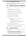
1.4 . . . . Notebook Expansion Capabilities . . . . . . . . . . . . . . . 1-21
1.4.1 . . . Memory Expansion . . . . . . . . . . . . . . . . . . . . . . . 1-21
1.4.2 . . . Headset and Microphone Option Kit. . . . . . . . . . . 1-22
1.4.3 . . . PS/2 Numeric Keypad Option . . . . . . . . . . . . . . . 1-22
1.4.4 . . . External Battery Charger . . . . . . . . . . . . . . . . . . . 1-22
1.4.5 . . . Extra Battery Option . . . . . . . . . . . . . . . . . . . . . . 1-22
1.4.6 . . . Notebook Carrying Case Options . . . . . . . . . . . . . 1-23
1.4.7 . . . PCMCIA Card Options . . . . . . . . . . . . . . . . . . . . . 1-23
1.5 . . . . Standard Test Features . . . . . . . . . . . . . . . . . . . . . . . 1-23
1.5.1 . . . Built-In Self Test . . . . . . . . . . . . . . . . . . . . . . . . . 1-23
1.5.2 . . . Diagnostics Program . . . . . . . . . . . . . . . . . . . . . . 1-24
1.6 . . . . Product Models . . . . . . . . . . . . . . . . . . . . . . . . . . . . . 1-24
Contents iii
1.7 . . . . Notebook Physical Description . . . . . . . . . . . . . . . . . 1-26
1.7.1 . . . Cover-Display Assembly. . . . . . . . . . . . . . . . . . . . 1-27
1.7.2 . . . System Base Assembly. . . . . . . . . . . . . . . . . . . . . 1-28
1.8 . . . . Notebook Functional Overview . . . . . . . . . . . . . . . . . 1-29
1.8.1 . . . System Processor . . . . . . . . . . . . . . . . . . . . . . . . 1-31
1.8.2 . . . Memory Subsystem . . . . . . . . . . . . . . . . . . . . . . . 1-31
1.8.3 . . . I/O Subsystem. . . . . . . . . . . . . . . . . . . . . . . . . . . 1-32
1.8.4 . . . AT Peripherals Subsystem . . . . . . . . . . . . . . . . . . 1-32
1.8.5 . . . Video Subsystem . . . . . . . . . . . . . . . . . . . . . . . . . 1-32
1.8.6 . . . External VGA Capability . . . . . . . . . . . . . . . . . . . 1-33
1.8.7 . . . Sound Subsystem . . . . . . . . . . . . . . . . . . . . . . . . 1-33
1.8.8 . . . Pointing Device Subsystem . . . . . . . . . . . . . . . . . 1-34
1.8.9 . . . Keyboard Subsystem. . . . . . . . . . . . . . . . . . . . . . 1-34
1.8.10 . . Hard Disk Subsystem . . . . . . . . . . . . . . . . . . . . . 1-37
1.8.11 . . Floppy Diskette Drive Subsystem . . . . . . . . . . . . . 1-38
1.8.12 . . Power Subsystem . . . . . . . . . . . . . . . . . . . . . . . . . 1-38
1.9 . . . . TravelMate 5000 Series Notebook Specifications . . . . 1-41
2 Installation
2.1 . . . . Introduction . . . . . . . . . . . . . . . . . . . . . . . . . . . . . . . 2-1
2.2 . . . . Unpacking Instructions . . . . . . . . . . . . . . . . . . . . . . . 2-1
2.3 . . . . Installing Internal Notebook Options . . . . . . . . . . . . 2-3
2.3.1 . . . Installing RAM Expansion (Optional) . . . . . . . . . . 2-3
2.3.2 . . . Installing PCMCIA Options . . . . . . . . . . . . . . . . . . 2-6
2.4 . . . . Installing External Notebook Options . . . . . . . . . . . . 2-7
2.4.1 . . . Installing the Optional Numeric Keypad . . . . . . . . 2-7
2.4.2 . . . Installing External Mic and Headphone Kit
. . . . . . . Option . . . . . . . . . . . . . . . . . . . . . . . . . . . . . . . . . 2-8
2.4.3 . . . Installing the EZ-Dock /EZ-Dock Plus Port
. . . . . . . Replicator (Option) . . . . . . . . . . . . . . . . . . . . . . . 2-9
2.5 . . . . Removing/Installing Battery Packs . . . . . . . . . . . . . 2-11
2.6 . . . . Installing Desktop Devices. . . . . . . . . . . . . . . . . . . . . 2-12
2.6.1 . . . Installing an External Keyboard/Mouse/Keypad . 2-13
2.6.2 . . . Installing External Parallel Printer . . . . . . . . . . . . 2-14
2.6.3 . . . Installing External Serial Port Device . . . . . . . . . 2-15
2.6.4 . . . Installing External VGA Monitor. . . . . . . . . . . . . . 2-16
iv Contents
2.6.5 . . . Installing External Headphone/Microphones . . . . 2-17
2.6.6 . . . Installing Devices With IR Interface . . . . . . . . . . . 2-18
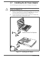
2.7 . . . . Installing the AC Power Adapter . . . . . . . . . . . . . . . . 2-19
2.8 . . . . Initial System Checkout . . . . . . . . . . . . . . . . . . . . . . 2-20
2.9 . . . . Configuring the System . . . . . . . . . . . . . . . . . . . . . . . 2-20
2.10 . . . Making Backups of System Software . . . . . . . . . . . . . 2-21
2.11 . . . Loading Application Software . . . . . . . . . . . . . . . . . . 2-21
2.12 . . . Securing Notebook to Workstation. . . . . . . . . . . . . . . 2-21
3 Operating Instructions
3.1 . . . . Introduction . . . . . . . . . . . . . . . . . . . . . . . . . . . . . . . 3-1
3.2 . . . . Notebook Controls and Indicators . . . . . . . . . . . . . . . 3-1
3.2.1 . . . Notebook Switches and Controls . . . . . . . . . . . . . 3-2
3.2.2 . . . Cover Release Latches . . . . . . . . . . . . . . . . . . . . . 3-3
3.2.3 . . . Notebook LED Displays . . . . . . . . . . . . . . . . . . . . 3-4
3.3 . . . . Internal Speaker/Microphone . . . . . . . . . . . . . . . . . . 3-7
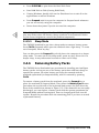
3.4 . . . . Operating Procedures . . . . . . . . . . . . . . . . . . . . . . . . 3-7
3.4.1 . . . Adjusting Sound Volume . . . . . . . . . . . . . . . . . . . 3-7
3.4.2 . . . Using Sound Utilities . . . . . . . . . . . . . . . . . . . . . . 3-8
3.4.3 . . . Warm Start or Warm Boot . . . . . . . . . . . . . . . . . . 3-8
3.4.4 . . . Responding to Low Battery Conditions . . . . . . . . . 3-8
3.4.5 . . . Minimizing Power Usage. . . . . . . . . . . . . . . . . . . . 3-8
3.4.6 . . . Removing Battery Packs. . . . . . . . . . . . . . . . . . . . 3-9
3.4.7 . . . Recharging the Battery Packs. . . . . . . . . . . . . . . . 3-10
3.4.8 . . . Running the DOS-Based Setup Program . . . . . . . 3-10
3.4.9 . . . Backing Up Your System Software . . . . . . . . . . . 3-10
3.4.10 . . Restoring Missing System Files . . . . . . . . . . . . . . 3-10
3.4.11 . . Rebuilding the System Software . . . . . . . . . . . . . . 3-11
4 Troubleshooting Procedures
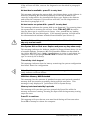
4.1 . . . . Overview of Fault Isolation Process . . . . . . . . . . . . . . 4-1
4.2 . . . . Troubleshooting Procedures . . . . . . . . . . . . . . . . . . . 4-4
4.2.1 . . . Troubleshooting a Power Supply Problem. . . . . . . 4-4
4.2.2 . . . Troubleshooting a Display Problem . . . . . . . . . . . 4-4
4.2.3 . . . Fault Isolation Using Selftest . . . . . . . . . . . . . . . . 4-5
Contents v
4.2.4 . . . PCMCIA Modem Problems . . . . . . . . . . . . . . . . . . 4-10
4.2.5 . . . Fault Isolation Using Diagnostics . . . . . . . . . . . . 4-10
5 Field Service
5.1 . . . . Introduction . . . . . . . . . . . . . . . . . . . . . . . . . . . . . . . 5-1
5.2 . . . . Preventive Maintenance. . . . . . . . . . . . . . . . . . . . . . . 5-1
5.2.1 . . . Cleaning the Computer . . . . . . . . . . . . . . . . . . . . 5-1
5.2.2 . . . Protecting the Disk Drives . . . . . . . . . . . . . . . . . . 5-1
5.2.3 . . . Handling the Computer Battery Packs . . . . . . . . . 5-2
5.2.4 . . . Restoring System Software . . . . . . . . . . . . . . . . . . 5-2
5.3 . . . . Required Tools and Equipment . . . . . . . . . . . . . . . . 5-2
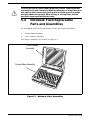
5.4 . . . . Notebook Field-Replaceable Parts and Assemblies . . . 5-3
5.4.1 . . . Cover-Display Assembly. . . . . . . . . . . . . . . . . . . . 5-4
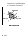
5.4.2 . . . System Base Assembly. . . . . . . . . . . . . . . . . . . . . 5-6
5.5 . . . . Notebook Sub-Assembly Removal and
. . . . . . . Replacement Procedures . . . . . . . . . . . . . . . . . . . . . . 5-9
5.5.1 . . . Removing/Replacing the Notebook
. . . . . . . Battery Pack . . . . . . . . . . . . . . . . . . . . . . . . . . . . 5-9
5.5.2 . . . Removing/Replacing PCMCIA Options . . . . . . . . . 5-10
5.5.3 . . . Removing/Replacing the Keyboard Assembly . . . . 5-10
5.5.4 . . . Removing/Replacing the Hard Drive Assembly. . . 5-12
5.5.5 . . . Removing/Replacing Expansion RAM Boards. . . . 5-13
5.5.6 . . . Opening/Replacing the Base Cover Assembly. . . . 5-14
5.5.7 . . . Removing/Replacing the Keyscan Board . . . . . . . 5-16
5.5.8 . . . Removing/Replacing the IR Board . . . . . . . . . . . . 5-17
5.5.9 . . . Removing/Replacing the Floppy Drive . . . . . . . . . 5-18
5.5.10 . . Removing/Replacing the LED Board . . . . . . . . . . 5-19
5.5.11 . . Removing/Replacing the Sleep Switch Board . . . . 5-20
5.5.12 . . Removing/Replacing the Sound/PCMCIA Board . 5-21
5.5.13 . . Removing/Replacing the Main Board . . . . . . . . . . 5-22
5.5.14 . . Removing/Replacing the Display Bezel. . . . . . . . . 5-24
5.5.15 . . Removing and Replacing the DAB Board . . . . . . . 5-25
5.5.16 . . Removing and Replacing the LCD
. . . . . . . Cover Assembly . . . . . . . . . . . . . . . . . . . . . . . . . . 5-26
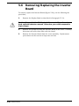
5.6 . . . . Removing/Replacing the Inverter Board . . . . . . . . . . 5-28
vi Contents
6 Illustrated Parts Listing
6.1 . . . . Introduction . . . . . . . . . . . . . . . . . . . . . . . . . . . . . . . 6-1
6.2 . . . . TM5000 Pentium, 10.4 TFT 810HD, Domestic
. . . . . . . Notebook with Pack, P/N 9798842-0001 . . . . . . . . . . 6-2
6.2.1 . . . TM5000, 10.4 TFT Color, 810HD, Domestic
. . . . . . . Unit Assembly, P/N 9798843, Parts Listing . . . . 6-4
6.2.2 . . . 10.4 Inch TFT Cover Display Assembly. . . . . . . . . 6-9
6.3 . . . . Assessory Kit Parts Listing for TM5000
. . . . . . . Series Notebooks. . . . . . . . . . . . . . . . . . . . . . . . . . . . 6-11
6.4 . . . . Board Level Illustrated Parts Listings . . . . . . . . . . . . 6-12
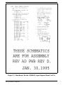
7 Schematic Diagrams
7.1 . . . . Introduction . . . . . . . . . . . . . . . . . . . . . . . . . . . . . . . 7-1
A Character Sets
A.1 . . . . Introduction . . . . . . . . . . . . . . . . . . . . . . . . . . . . . . . A-1
B Keyboard Layouts
B.1 . . . . Introduction . . . . . . . . . . . . . . . . . . . . . . . . . . . . . . .
C PC-Doctor Diagnostics
C.1 . . . . Introduction . . . . . . . . . . . . . . . . . . . . . . . . . . . . . . . C-1
C.2 . . . . Starting PC-Doctor . . . . . . . . . . . . . . . . . . . . . . . . . . C-1
C.3 . . . . Keyboard Navigation . . . . . . . . . . . . . . . . . . . . . . . . . C-2
C.4 . . . . Mouse Navigation . . . . . . . . . . . . . . . . . . . . . . . . . . . C-2
C.5 . . . . PC-Doctor Menus . . . . . . . . . . . . . . . . . . . . . . . . . . . C-3
C.5.1 . . . Online Help (?) . . . . . . . . . . . . . . . . . . . . . . . . . . . C-3
C.5.2 . . . Diagnostics . . . . . . . . . . . . . . . . . . . . . . . . . . . . . C-3
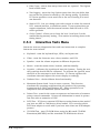
C.5.3 . . . Interactive Tests Menu . . . . . . . . . . . . . . . . . . . . . C-4
C.5.4 . . . Hardware Info Menu . . . . . . . . . . . . . . . . . . . . . . C-5
C.5.5 . . . Utility Menu . . . . . . . . . . . . . . . . . . . . . . . . . . . . . C-5
C.6 . . . . Quitting PC-Doctor . . . . . . . . . . . . . . . . . . . . . . . . . . C-6
C.7 . . . . Remote Operation . . . . . . . . . . . . . . . . . . . . . . . . . . . C-6
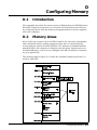
D Configuring Memory
D.1 . . . . Introduction . . . . . . . . . . . . . . . . . . . . . . . . . . . . . . . D-1
Contents vii
D.2 . . . . Memory Areas . . . . . . . . . . . . . . . . . . . . . . . . . . . . . . D-1
D.2.1 . . . Extended Memory . . . . . . . . . . . . . . . . . . . . . . . . D-2
D.2.2 . . . Expanded Memory . . . . . . . . . . . . . . . . . . . . . . . . D-2
D.3 . . . . Memory Device Drivers . . . . . . . . . . . . . . . . . . . . . . . D-3
D.3.1 . . . Installing Device Drivers . . . . . . . . . . . . . . . . . . . D-3
D.3.2 . . . EMM386.EXE . . . . . . . . . . . . . . . . . . . . . . . . . . . D-4
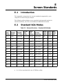
E Screen Standards
E.1 . . . . Introduction . . . . . . . . . . . . . . . . . . . . . . . . . . . . . . . E-1
E.2 . . . . Standard VGA Modes . . . . . . . . . . . . . . . . . . . . . . . . E-1
E.3 . . . . Extended VGA Modes . . . . . . . . . . . . . . . . . . . . . . . . E-2
E.4 . . . . Standard LCD Modes . . . . . . . . . . . . . . . . . . . . . . . . E-5
E.5 . . . . Extended LCD Modes . . . . . . . . . . . . . . . . . . . . . . . . E-6
E.6 . . . . Standard SimulSCAN Modes . . . . . . . . . . . . . . . . . . . E-6
E.7 . . . . Extended SimulScan Modes . . . . . . . . . . . . . . . . . . . E-7
F Added Interrupt 15 Functions
F.1 . . . . Introduction . . . . . . . . . . . . . . . . . . . . . . . . . . . . . . . F-1
F.2 . . . . Function 46h - Subfunction 00h
. . . . . . . Read Power/Modem Configuration . . . . . . . . . . . . . . F-1
F.3 . . . . Function 46h - Subfunction 01h
. . . . . . . Modify Power/Modem Configuration . . . . . . . . . . . . . F-2
F.4 . . . . Function 46h - Subfunction 03h
. . . . . . . Get/Set Battery Status . . . . . . . . . . . . . . . . . . . . . . . F-3
F.5 . . . . Function F7h - Get CPU Speed . . . . . . . . . . . . . . . . . F-4
F.6 . . . . Function F8h - Set CPU Speed . . . . . . . . . . . . . . . . . F-5
F.7 . . . . Function F9h - Subfunction 5Eh
. . . . . . . Get Model Information. . . . . . . . . . . . . . . . . . . . . . . . F-5
F.8 . . . . Function F9h - Subfunction 60h
. . . . . . . Get Standby Level . . . . . . . . . . . . . . . . . . . . . . . . . . . F-7
F.9 . . . . Function F9h - Subfunction 61h
. . . . . . . Set Standby Level . . . . . . . . . . . . . . . . . . . . . . . . . . . F-7
F.10 . . . Function F9h - Subfunction 63h
. . . . . . . Get Extended Model ID . . . . . . . . . . . . . . . . . . . . . . . F-8
F.11 . . .
.......
viii Contents
Function FAh - Subfunction 00h
Get RAM Information . . . . . . . . . . . . . . . . . . . . . . . . F-9
G
F.12 . . .
.......
Function FAh - Subfunction 03h
Get Video Information . . . . . . . . . . . . . . . . . . . . . . . F-9
F.13 . . .
.......
Function FAh - Subfunction 05h
Get Setup Information . . . . . . . . . . . . . . . . . . . . . . . F-12
BIOS Updates
G.1 . . . . Introduction . . . . . . . . . . . . . . . . . . . . . . . . . . . . . . . G-1
G.2 . . . . Updates Procedure . . . . . . . . . . . . . . . . . . . . . . . . . . G-1
Illustrations
Figure
Title
Page No.
1-1 . . . . TravelMate 5000 Series Notebook Computers . . . . . . 1-2
1-2 . . . . TM5000 Pentium Notebook, Simplified Diagram . . . . 1-3
1-3 . . . . TM5000 Pentium Series Notebook Features. . . . . . . . 1-5
1-4 . . . . TM5000 Intelligent Battery Packs . . . . . . . . . . . . . . . 1-6
1-5 . . . . TM5000 Notebook Peripherals . . . . . . . . . . . . . . . . . . 1-7
1-6 . . . . TM5000 Software Features . . . . . . . . . . . . . . . . . . . . 1-9
1-7 . . . . Notebook Expansion Features . . . . . . . . . . . . . . . . . . 1-11
1-8 . . . . EZ-Dock Plus Port Replicator . . . . . . . . . . . . . . . . . . 1-13
1-9 . . . . RAM Expansion Features . . . . . . . . . . . . . . . . . . . . . 1-15
1-10 . . . Internal Keyboard for TM5000 Series . . . . . . . . . . . . 1-17
1-11 . . . Notebook External Ports . . . . . . . . . . . . . . . . . . . . . . 1-19
1-12 . . . Infrared Interface . . . . . . . . . . . . . . . . . . . . . . . . . . . 1-20
1-13 . . . Notebook Major Assemblies . . . . . . . . . . . . . . . . . . . . 1-26
1-14 . . . Cover Display Assembly FRUs . . . . . . . . . . . . . . . . . . 1-27
1-15 . . . Exploded View of Notebook Base Assembly . . . . . . . . 1-28
1-16 . . . TM5000 Series, Functional Block Diagram . . . . . . . . 1-30
1-17 . . . Notebook Pointing Device . . . . . . . . . . . . . . . . . . . . . 1-34
1-18 . . . Keyboard Layout . . . . . . . . . . . . . . . . . . . . . . . . . . . . 1-35
1-19 . . . Notebook Controls/Indicators . . . . . . . . . . . . . . . . . . 1-37
2-1 . . . . TM5000 Series Notebook Packaging Diagram . . . . . . 2-2
2-2 . . . . TM5000 Series Accessory Kit Packaging . . . . . . . . . . 2-3
2-3 . . . . Installing RAM Expansion Module (Option) . . . . . . . . 2-5
Contents ix
Illustrations
Figure
Title
Page No.
2-4 . . . . Installing PCMCIA Options . . . . . . . . . . . . . . . . . . . . 2-6
2-5 . . . . Installing the Optional PS/2 Numeric Keypad . . . . . . 2-7
2-6 . . . . Installing the External Microphone and. . . . . . . . . . . 2-8
2-7 . . . . Opening the Notebook Connector Covers . . . . . . . . . . 2-9
2-8 . . . . Installing the EZ-Dock Port Replicator/Plus . . . . . . . 2-10
2-9 . . . . Battery Pack Removal/Replacement . . . . . . . . . . . . . 2-11
2-10 . . . Notebook Computer External Ports . . . . . . . . . . . . . . 2-12
2-11 . . . External Mouse/Numeric Keypad Port . . . . . . . . . . . 2-13
2-12 . . . Parallel Printer Connector Pinouts. . . . . . . . . . . . . . . 2-14
2-13 . . . Serial Port Pinouts . . . . . . . . . . . . . . . . . . . . . . . . . . 2-15
2-14 . . . External VGA Monitor Connector Pinouts . . . . . . . . . 2-16
2-15 . . . Notebook Audio Connectors . . . . . . . . . . . . . . . . . . . 2-17
2-16 . . . Installing Devices with Infrared Interface. . . . . . . . . . 2-18
2-17 . . . Installing the AC Adapter . . . . . . . . . . . . . . . . . . . . . 2-19
2-18 . . . Notebook Security Ring . . . . . . . . . . . . . . . . . . . . . . . 2-21
3-1 . . . . Notebook Controls and Indicators . . . . . . . . . . . . . . . 3-2
3-2 . . . . The Point. . . . . . . . . . . . . . . . . . . . . . . . . . . . . . . . . . 3-4
3-3 . . . . Battery/Indicators Controls. . . . . . . . . . . . . . . . . . . . 3-6
3-4 . . . . Internal Speaker/Microphone Locations . . . . . . . . . . 3-7
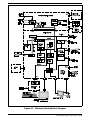
4-1 . . . . Notebook Computer Troubleshooting. . . . . . . . . . . . . 4-2
4-2 . . . . Notebook Detailed Block Diagram . . . . . . . . . . . . . . . 4-3
5-1 . . . . Notebook Major Assemblies . . . . . . . . . . . . . . . . . . . . 5-3
5-2 . . . . Cover Display Assembly, . . . . . . . . . . . . . . . . . . . . . . 5-4
5-3 . . . . TM5000P Base Assembly. . . . . . . . . . . . . . . . . . . . . . 5-6
5-4 . . . . Battery Pack Removal/Replacement . . . . . . . . . . . . . 5-9
5-5 . . . . PCMCIA Device, Removal/Replacement. . . . . . . . . . . 5-10
5-6 . . . . Keyboard Assembly, Removal/Replacement . . . . . . . 5-11
5-7 . . . . Hard Drive Assembly, Removal/Replacement . . . . . . 5-12
5-8 . . . . Expansion RAM Board(s), Removal/Replacement . . . 5-13
x Contents
Illustrations
Figure
Title
Page No.
5-9 . . . . Opening the Base Cover . . . . . . . . . . . . . . . . . . . . . . 5-15
5-10 . . . Keyscan Board, Removal/Replacement . . . . . . . . . . . 5-16
5-11 . . . IR Board, Removal/Replacement . . . . . . . . . . . . . . . . 5-17
5-12 . . . Floppy Drive, Removal/Replacement . . . . . . . . . . . . . 5-18
5-13 . . . The LED Board, Removal/Replacement . . . . . . . . . . . 5-19
5-14 . . . Sleep Board Assembly, Removal/Replacement . . . . . 5-20
5-15 . . . Sound/PCMCIA Board, Removal/Replacement . . . . . 5-21
5-16 . . . Main Board, Removal/Replacement . . . . . . . . . . . . . 5-23
5-17 . . . Display Bezel, Removal/Replacement . . . . . . . . . . . . 5-24
5-18 . . . Removing/Replacing the DAB Board . . . . . . . . . . . . 5-26
5-19 . . . LCD Cover Assembly, Removal/Replacement . . . . . . 5-27
5-20 . . . Removing/Replacing the Inverter Board . . . . . . . . . . 5-29
6-1 . . . TM5000 Pentium, 10.4 TFT, 810HD, Domestic
. . . . . . . Notebook with Pack, P/N 9798842-0001 . . . . . . . . . . 6-2
6-2 . . . . TM5000, 10.4 TFT Color, 810HD, Domestic Unit
. . . . . . . Assembly, P/N 9798843 (2 Sheets) . . . . . . . . . . . . . . 6-4
6-3 . . . . 10.4 TFT Color TFT, Cover Display Assembly,
. . . . . . . P/N 9786250-0003 . . . . . . . . . . . . . . . . . . . . . . . . . . 6-9
6-4 . . . . Main Board (P54, 75MHz), P/N 9798803-0001
. . . . . . . (2 Sheets) . . . . . . . . . . . . . . . . . . . . . . . . . . . . . . . . . 6-13
6-5 . . . . PCMCIA/Sound Board, P/N 9786205-0001
. . . . . . . (2 Sheets) . . . . . . . . . . . . . . . . . . . . . . . . . . . . . . . . . 6-26
6-6 . . . . Keyscan Board, P/N 9786209-0001 . . . . . . . . . . . . . 6-35
6-7 . . . . IR Board, P/N 9798813-0001 . . . . . . . . . . . . . . . . . . 6-39
6-8 . . . . Sleep Board, P/N 9786148-0001 . . . . . . . . . . . . . . . . 6-41
6-9 . . . . LED Board, P/N 9786128-0001 . . . . . . . . . . . . . . . . 6-42
6-10 . . . Inverter Board, P/N 9786134-0001 . . . . . . . . . . . . . . 6-43
6-11 . . . DAB Board, P/N 9786273-0001 . . . . . . . . . . . . . . . . 6-48
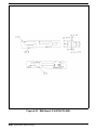
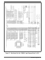
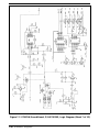
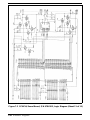
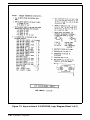
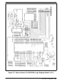
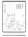
7-1 . . . . Main Board, Part No. 9798803, Logic Diagram
. . . . . . . (22 Sheets) . . . . . . . . . . . . . . . . . . . . . . . . . . . . . . . . 7-2
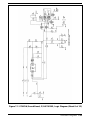
7-2 . . . . PCMCIA/Sound Board, P/N 9786205, Logic Diagram
. . . . . . . (12 Sheets) . . . . . . . . . . . . . . . . . . . . . . . . . . . . . . . . 7-24
Contents xi
Illustrations
Figure
Title
Page No.
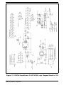
7-3 . . . . Keyscan Board, P/N 9786209, Logic Diagram
. . . . . . . (5 Sheets) . . . . . . . . . . . . . . . . . . . . . . . . . . . . . . . . . 7-36
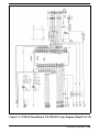
7-4 . . . . Sleep Switch Board, P/N 9786148, Logic Diagram . . 7-41
7-5 . . . . IR Board, P/N 9798813, Logic Diagram (2 Sheets). . . 7-42
7-6 . . . . LED Board, P/N 9796128, Logic Diagram
. . . . . . . (2 Sheets) . . . . . . . . . . . . . . . . . . . . . . . . . . . . . . . . . 7-44
7-7 . . . . 8/16 MB RAM Exp. Board, P/N 9798816,
. . . . . . . Logic Diagram . . . . . . . . . . . . . . . . . . . . . . . . . . . . . . 7-46
7-8 . . . . Inverter Board, P/N 9796134, Logic Diagram
. . . . . . . (2 Sheets) . . . . . . . . . . . . . . . . . . . . . . . . . . . . . . . . . 7-47
7-9 . . . . Display Adapter Board, P/N 9786273, Logic Diagram
. . . . . . . (2 Sheets) . . . . . . . . . . . . . . . . . . . . . . . . . . . . . . . . . 7-49
A-1 . . . . Code Page 437, United States . . . . . . . . . . . . . . . . . . A-2
A-2 . . . . Code Page 850, Multilingual . . . . . . . . . . . . . . . . . . . A-3
A-3 . . . . Code Page 863, Canadian-French . . . . . . . . . . . . . . . A-4
A-4 . . . . Code Page 865, Nordic. . . . . . . . . . . . . . . . . . . . . . . . A-5
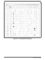
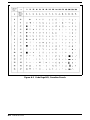
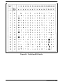
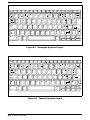
B-1 . . . . U.S. English Keyboard Layout . . . . . . . . . . . . . . . . . . B-1
B-2 . . . . U.K. English Keyboard Layout. . . . . . . . . . . . . . . . . . B-1
B-3 . . . . Danish Keyboard Layout . . . . . . . . . . . . . . . . . . . . . . B-2
B-4 . . . . French Keyboard Layout . . . . . . . . . . . . . . . . . . . . . . B-2
B-5 . . . . German Keyboard Layout . . . . . . . . . . . . . . . . . . . . . B-3
B-6 . . . . Italian Keyboard Layout . . . . . . . . . . . . . . . . . . . . . . B-3
B-7 . . . . Norwegian Keyboard Layout . . . . . . . . . . . . . . . . . . . B-4
B-8 . . . . Spanish Keyboard Layout . . . . . . . . . . . . . . . . . . . . . B-4
B-9 . . . . Swedish/Finnish Keyboard Layout . . . . . . . . . . . . . . B-5
B-10 . . . Swiss Keyboard Layout . . . . . . . . . . . . . . . . . . . . . . . B-5
B-11 . . . Portuguese Keyboard Layout . . . . . . . . . . . . . . . . . . . B-6
B-12 . . . Belgium Keyboard Layout . . . . . . . . . . . . . . . . . . . . . B-6
xii Contents
Tables
Table
Title
Page No.
1-1 . . . . TravelMate 5000 Series Notebook Domestic/
. . . . . . . International Configurations . . . . . . . . . . . . . . . . . . 1-24
1-2 . . . . TravelMate 5000 Series Notebook Specifications . . . . 1-41
4-1 . . . . Self-Test Error Messages . . . . . . . . . . . . . . . . . . . . . . 4-6
4-2 . . . . Self Test Beep Messages . . . . . . . . . . . . . . . . . . . . . . 4-8
5-1 . . . . Cover Display Assembly, Field
. . . . . . . Replaceable Units (FRUs) . . . . . . . . . . . . . . . . . . . . . 5-5
5-2 . . . . Base Assembly, Field Replaceable Units (FRUs). . . . . 5-7
5-3 . . . . Notebook CRUs (Customer Replaceable Units). . . . . . 5-8
6-1 . . . . Dash Number Suffixes for International Countries . . 6-1
6-2 . . . . TM5000 Pentium, 10.4 TFT, 810HD, Domestic
. . . . . . . Notebook with Pack, P/N 9798842-0001 . . . . . . . . . . 6-3
6-3 . . . . TM5000, 10.4 TFT Color, 810HD, Domestic Unit
. . . . . . . Assembly, P/N 9798843, Parts Listing . . . . . . . . . . 6-6
6-4 . . . . 10.4 Inch Color TFT Cover Display Assembly,
. . . . . . . P/N 9786250-0003, Parts Listing . . . . . . . . . . . . . . . 6-10
6-5 . . . . Assessory Kit (P/N 9786168-XXXX) for the TM5000
. . . . . . . Series Notebooks . . . . . . . . . . . . . . . . . . . . . . . . . . . . 6-11
6-6 . . . . Main Board (P54, 75MHz), P/N 9798803-0001,
. . . . . . . Parts Listing . . . . . . . . . . . . . . . . . . . . . . . . . . . . . . . 6-15
6-7 . . . . PCMCIA/Sound Board, P/N 9786205-0001,
. . . . . . . Parts Listing . . . . . . . . . . . . . . . . . . . . . . . . . . . . . . . 6-28
6-8 . . . . Keyscan Board, P/N 9786209-0001, Parts Listing . . . 6-38
6-9 . . . . IR Board, P/N 9798813-0001, Parts Listing . . . . . . . 6-41
6-10 . . . Sleep Board, P/N 9786148-0001, Parts Listing . . . . . 6-43
6-11 . . . LED Board, P/N 9786128-0001, Parts Listing . . . . . . 6-44
6-12 . . . Inverter PWB, P/N 9786134-0001, Parts Listing . . . . 6-46
6-13 . . . DAB Board, P/N 9786273-0001, Parts Listing. . . . . . 6-51
7-1 . . . . Schematic Drawing Index . . . . . . . . . . . . . . . . . . . . . 7-1
C-1 . . . . PC-Doctor Key Assignments . . . . . . . . . . . . . . . . . . . C-2
C-2 . . . . Test Selection Menu Special Keys . . . . . . . . . . . . . . . C-2
E-1 . . . . External Monitors - Standard VGA Modes . . . . . . . . . E-1
Contents xiii
Tables
Table
Title
Page No.
E-2 . . . . External Monitors Extended VGA Modes . . . . . . . . . . E-2
E-3 . . . . Standard VGA LCD-Only Video Modes . . . . . . . . . . . E-5
E-4 . . . . Extended LCD-Only Video Modes . . . . . . . . . . . . . . . E-6
E-5 . . . . Standard SimulSCAN Video Modes . . . . . . . . . . . . . . E-6
E-6 . . . . Extended SimulSCAN Video Modes . . . . . . . . . . . . . . E-7
xiv Contents
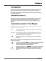
Preface
Introduction
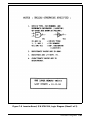
This manual contains operation, installation and maintenance instructions
for the Texas Instruments TravelMate 5000 Series Notebook Computers.
This preface introduces the contents of the manual and lists and describes
all related publications.
Intended Audience
This manual is primarily intended for use by qualified service technicians
assigned to TravelMate computer repair operations. However, several
sections contain overview information useful to a general (less-technical)
audience.
Conventions Used In This Manual
Throughout this manual, the following conventions are used to distinguish
between different elements of text:
Italics
Used to denote setup program items, key words, and references
to other publications
Monospace
Used for prompts and menus that display during operation of
the computer (including text generated by the computer) and
entries to be entered on the keyboard
Bold
Denotes a control panel or keyboard key, switch, or disk drive
designator.
Note that several symbols are used throughout this manual to advise you of
important information.
n
c
This symbol indicates a Note concerning operating or maintenance
procedures or information you should know to help you
operate or maintain the notebook computer.
This symbol alerts you to a Warning or Caution about a potentially
hazardous condition that could cause bodily injury or result in
damage to your computer, computer accessories or computer
data.
Preface xv
Contents
This manual contains seven sections and seven appendices including:
•
•
•
•
•
•
•
xvi Preface
Section 1: General Description— Introduces the TravelMate 5000
series Notebook Computers and identifies all standard and optional
features. This section also provides a functional overview of notebook
computer operation, identifies the major assemblies and subassemblies,
and provides a summary list of specifications.
Section 2: Installation — Provides information needed to unpack the
notebook computer and associated accessories, install all options and
accessories and test the computer for proper operation.
Section 3: Operating instructions — Provides operating instructions
for the notebook computer line. The first part of the section introduces
the notebook computer operating controls and indicators. The second
part of the section describes the notebook computer modes of operation.
The remainder of the section provides notebook computer operation and
configuration procedures.
Section 4: Troubleshooting — Describes the self test and diagnostics
programs and provides instructions for using the tests and interpreting
any error messages; the remainder of the section provides guidelines for
isolating computer malfunctions down to the replaceable subassembly
or component.
Section 5: Field Servicing — Describes the preventive and corrective
maintenance procedures for the TravelMate 5000 Series Notebook
Computers. The first part of the section contains preventive
maintenance instructions and general instructions for the care and
maintenance of the notebook computer; the second part of the section
provides a listing of all field replaceable assemblies and components
and the remainder of the section contains assembly
removal/replacement procedures.
Section 6: Illustrated Parts Listing —Contains assembly drawings
and lists of materials for the TM5000 Pentium, 75 MHz, 10.4 inch active
matrix color, 8MB Memory, 810 Hard Drive notebook computers.
Section 7: Schematic Diagrams — Provides schematic diagrams for
the intial release of the TM5000 Series Notebook Computers..
•
Appendix A: TM5000 Character Sets
•
Appendix B: TM5000 Keyboard Layouts
•
Appendix C: PC-Doctor Diagnostics
•
Appendix D: Configuring TM5000 Memory
•
Appendix E: Supported External Monitors
•
Appendix F: Added Interrupt 15 Functions
•
Appendix G: BIOS Updates
Other Manuals About the Notebook
Computer
The following documents provide additional information about the
TravelMate 5000 Series Computers:
•
•
•
•
•
•
TravelMate 5000 Series Notebook Computers Quick Start Manual,
TI P/N 9786164-0001- provides the basic information needed for
first-time users to configure and begin using the notebook.
TravelMate 5000 Series Notebook Computers, Users Guide, TI P/N
9786163-0001- provides basic operating instructions for the notebook.
TravelMate 5000 Series Notebook Computers User’s Reference
Manual, TI P/N 9786167-0001- provides software loading and
configuration instructions for the TM5000 Series Notebook Computers.
TravelMate 5000 Series Notebook Computers Safety Instructions,
TI P/N 9786165-0001- provides safety instructions for using the
TM5000 Series multi-media notebook ; provides handling and disposal
instructions for battery packs.
Adaptec EZ-SCSI for DOS/Windows User’s Manual- TI P/N
0978866-0001- provides instructions for using the EZ-SCSI install
program when installing SCSI options on the EZ-Dock Plus Port
Replicator (docking system).
PCMCIA PhoenixCARD Manager User’s Guide, TI P/N
9791792-0001- provides user instructions for running the PCMCIA
install program when adding/removing PCMCIA option cards to/from
the TM5000 Series Notebook Computers.
Ordering Parts and Supplies
To order a copy of any TI publication or to order option kits, spare parts or
supplies for your notebook computer, contact your TI Reseller or:
Telephone toll-free: 1-800-TI TEXAS
Preface xvii
1
General Description
1.1
Introduction
This manual contains field and factory level servicing information for the
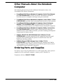
TravelMate 5000 Series of Notebook Computers (Figure 1-1),
manufactured by Texas Instruments, Incorporated.
This section provides a general overview of the TravelMate 5000 Series of
Notebook Computers, describes the standard and optional features, and
identifies the major assemblies and subassemblies. This section also
contains detailed functional and environmental specifications for the
TravelMate 5000 Series Notebook Computers herein referred to as the
Notebook Computer.
Initially, this manual covers the following TravelMate 5000 Notebook:
•
TM5000 Pentium 75 MHz, 10.4 Inch Active Matrix Color Display, 8MB
Memory, 810 Million Byte Hard Drive, Texas Instruments Part No.
9798842
As additional models are introduced, the product differences will be
documented as addendums to this maintenance manual.
General Description 1-1
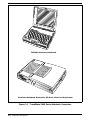
TM5000 Pentium Notebook
Pentium Notebook Docked to EZ-Dock Plus Port Replicator
Figure 1-1 TravelMate 5000 Series Notebook Computers
1-2 General Description
1.2
Product Overview
The TravelMate 5000 Series Notebook Computers are high performance,
multimedia notebooks powered by the Intel P54-C Pentium tm superscalar
processor with built-in co-processor and dual, on-chip, 16KB data and
instruction caches. The 3-volt, Pentium chip, packaged in the TAB TCP
format, generates a 75 MHz clock processing rate. An off-chip, 256KB L2
cache buffer using asynchronous, 15 ns SRAM, is also implemented to
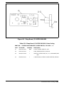
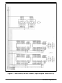
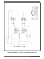
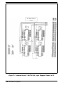
support the power of the Pentium. A simplified block diagram of the TM5000
Pentium Notebook is provided in Figure 1-2.
Figure 1-2 TM5000 Pentium Notebook, Simplified Diagram
General Description 1-3
All members of the TM5000 family come standard with 8MB of 70-ns
page-interleaved, DRAM on the main board (expandable to 32MB with
user-installable RAM Expansion Boards based on 16M DRAM technology).
The Basic Input Output System (BIOS) firmware for the main system and
for the VGA BIOS is stored on a 256K x 8 Flash reprogrammable Flash
ROM. A Boot Block feature permits downloading of new BIOS changes
without having to physically replace the ROMs. Execution from ROM is
initially 8-bits wide but 32-bit performance is available when using the
Shadow ROM feature.
To take full advantage of the Pentium’s powerful multi-tasking capabilities,
the TM5000 series implements a 50MHZ, 64-bit high speed system bus that
interconnects the critical CPU, Memory and hard drive components. The
50-MHz system bus drives a 33 MHz, 32-bit, Peripheral Components
Interface (PCI) bus that supports the video subsystem, expansion
subsystem with other higher speed peripherals. The PCI bus also drives a
conventional 8MHz AT Bus for compatibility with AT peripherals (onboard
1.44MB floppy, keyboard, pointing device, etc.).
1.2.1
MultiMedia Features
As standard features, the notebooks contain powerful audio and video
multimedia capabilities. A built-in SoundBlaster compatible sound board,
Jazz 16 Sound Software, plus internal speaker and microphone, and audio
input and output jacks give the notebooks a wide range of sound
capabilities.
The notebooks also offer powerful new video features on the PCI Expansion
Bus including the MotionVideotm Architecture (MVATM). MVATM supports
storage and playback of video clips (320 x 240 clips can be played back at
30 fps with 24 bpp color quality). The notebook’s video controller has a
feature interface that is VESA VAFC compatible enabling a system to
provide live video overlay capability.
A control/data interface is also available on the PCI bus that allows an
implementation of NTSC/PAL (commercial TV) output required to display
graphics or video on standard TVs.
1-4 General Description
Built-in Microphone
Color LCD
4mm, 83/84
Key Keyboard
Built-In Speaker
Two PCMCIA Option Slots
The Point
(Internal Mouse)
Infra-Red Interface
Dual Intelligent
Battery Packs
1.44MB Floppy Drive
User Replaceable
810 Hard Drive
(Accessible from bottom)
Pentium P54-C Processor
(Internal)
Cover Latch, Right
Audio Inputs and
Outputs
Provisions for up to 24 MB
of Expansion RAM
(Underneath Floppy Drive)
Cover Latch, Left
External PS/2 Mouse
or External PS/2 Keypad
Option
Figure 1-3 TM5000 Pentium Series Notebook Features
General Description 1-5
1.2.2
Dual Intelligent Battery Packs
The TM5000 notebook series support the use of two hot plugable intelligent
battery packs (with front panel charge remaining indicators) that allow for
battery removal and replacement while the system is operational (as long as
one battery contains a partial charge). The notebooks use rechargeable
Lithium-Ion (Li-Ion) batteries. These battery packs are ejected from the
front of the notebook using battery eject switches located just above the
keyboard (See Figure 1-4).
Battery Eject
Switches
Dual Intelligent Battery Packs
Charge LED Indicators
Charge Display Button
Approx.
Charge %
76 to 100%
51 to 75%
26 to 50%
11 to 25%
0 to 10 %
.
LED1 LED2 LED3 LED4
ON
ON
ON
ON
RED
ON
ON
ON
OFF
OFF
ON
ON
OFF
OFF
OFF
ON
OFF
OFF
OFF
OFF
NOTE: When battery is 100% charged, all
LEDs extinguish; also LEDs extinguish when
battery is removed from unit.
Figure 1-4 TM5000 Intelligent Battery Packs
1-6 General Description
1.2.3
Standard Peripherals
As standard features, the TM5000 notebooks include a built-in 3.5 " Floppy
Drive and a user-replaceable, Hard Disk Drive. (Initially, either 810 Million
Byte drive or 524 million Byte Drive).
The hard drive uses the Fast IDE interface (with a 128 KB buffer) and has
an average access time of 12 milliseconds or less. The hard drive is
interfaced to the high speed, 64-bit, VL local bus for increased performance.
Additionally, the notebook includes two PCMCIA sockets and configuration
software that can accommodate additional plug and play PCMCIA devices.
810 or 524 Million Byte
User Replaceable
Hard Disk Drive
Connectors for External
Peripherals
PCMCIA Sockets
(Up to two Option Devices)
1.44 MB Floppy Drive
Figure 1-5 TM5000 Notebook Peripherals
General Description 1-7
1.2.4
Preloaded Software
All members of the TM5000 family are preloaded with the following system
software:
•
DOS v6.2 Operating System (or later version)
•
Windows for Workgroups v3.11 (or later version)
•
Advanced BatteryPro Power Management
•
Jazz 16 Sound Control software
•
•
•
•
Phoenix PCMCIA PhoenixCard Manager Plus tm (for installing PCMCIA
options)
Laptop File Management System- this utility helps you manipulate files
and directories stored on your hard drive. It includes such features as
copying multiple directories to diskette or disk, deleting directories and
files, finding files using wild card characters, renaming directories,
displaying hard disk and floppy statistics, sorting directories, etc.
Variety of productivity enhancement utilities including:
•
WinMode Utility - selects video output to the built-in LCD
screen, CRT, or both
•
Password utility that allows you to install or remove a
password system for files security
•
Super Shutdown Utility that allows you to close open
applications and exit Windows faster than with the
conventional process.
•
Alarms off utility (Walarms)- disables the cover closed alarm
and the low-battery alarm
•
Drop N’Go Utility- allows you to display frequently run
applications as icons on your desktop or as menu items
under the File Manager utility.
•
MIDI Mapper Utility- allows you to select a MIDI setup for a
sound device, create a new setup, edit existing maps, etc.
•
Information Utilities including: Battery Level (Wbattery),
Battery Saving Software Help information (BatteryPro APM),
and Battery Tips (Battips).
PC-Doctor Diagnostics
All system software is shipped preloaded on the hard drive and not supplied
in floppy form (user must create a set of system backup diskettes as
described in Section 3 of this manual or purchase a set of software
diskettes).
The TM5000 Series Notebooks are shipped with only one diskette: the
System Recovery Diskette used to rebuilt system software using the backup
diskettes. Figure 1-6 summarizes the TM5000 software features.
1-8 General Description
FLASH ROM BIOS
MS-DOS Operating System
Microsoft Windows
Online Documentation
TI Utilities
Information
Utilities
BatteryPro
WinMode
Utility
Productivity
Utilities
Drop-N-Go
Utility
Super
Shutdown
Password
Utility
Windows
User's
Guide
MS-DOS
User's
Guide
TM5000
User's
Guide
TM5000 User's
Online Reference
PC-Doctor
Online
Reference
Configuration Software
PCMCIA
Sound Utilities
Pocket
Recorder
Pocket
Mixer
Pocket
CD
MIDI
Mapper
Infrared
Diagnostics
PC-Doctor
Diagnostics
Figure 1-6 TM5000 Software Features
1.2.5
Preloaded Online Documentation
The TM5000 Series Notebooks are also factory-loaded with the following
online manuals:
•
TravelMate 5000 Series Notebook User’s Guide
General Description 1-9
•
TravelMate 5000 Series Notebook Computers Online User’s Reference
Manual, TI P/N 9786167-0001- provides more comprehensive
application loading and configuration instructions for the TM5000
Series Notebook Computers.
•
MS-DOS User’s Guide
•
Windows User’s Guide
•
PC-Doctor Technical Reference Manual- provides user instructions for
the PC-Doctor Diagnostics supplied with the TM5000 Product line.
1.2.6
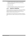
Expansion Capabilities
Expansion capabilities built into the notebook include two Type III PCMCIA
card slots, an external 160 pin Expansion Bus connection that includes the
33 MHz PCI Expansion Bus with sidebands to drive external Port
Expanders, and a wide variety of external connectors for attaching the
notebook to a desktop environment (See Figure 1-7).
Support features are also incorporated into the notebooks to permit user
upgrade of hard drive as larger capacity drives come online. User-installable
expansion RAM is also available to expand system memory from 8 MB to 32
MB.
1-10 General Description
Audio In
(From CD ROM
Player, Tape Player, Etc.
User-Replaceable Hard Drive
(Unit initially equipped with 810 Drive)
Audio Out
(To Headphones
or External Speakers)
External Microphone
Input Jack
RAM Expansion Capabilities
(User Installable Options to Add
Additional 8MB or up to 24MB
of fast RAM Memory)
PS/2 Port (External PS/2 Keyboard or
Mouse; or 101-Type Keyboard
with adapter)
Infra-Red Interface
(Wireless connection
to any device with
InfraRed Interface)
PCMCIA Slots
15-Pin External
VGA Port
25-Pin Parallel
Bi-Directional Port
9-Pin Serial
Port
160-Pin PCI/Sidebands Expansion
Bus for connecting to a Notebook Docking
System or Port Replicator
EZ-Dock PlusPort Replicator adds SCSI
and 16-bit Sound (MIDI) features plus
desktop connectivity to Desktop Environment.
Figure 1-7 Notebook Expansion Features
General Description 1-11
As new versions of BIOS become available, they can be downloaded into
Flash ROM from floppy disk without physically having to replace the ROMs.
(See Appendix G for details.)
Two Port Replicator system options are also available to simplify
removing/installing the notebook into a desktop environment:
•
EZ-Dock Plus Port Replicator
•
EZ-Dock Port Replicator
1.2.6.1
EZ-Dock Plus Port Replicator
The EZ-Dock PLUS Port Replicator (Figure 1-8) is a small footprint, manual
docking system that attaches to the 160-pin, PCI Expansion Bus Connector
and to the 15-pin External VGA Connector on the rear of a TM5000
Notebook.
This replicator breaks out the expansion bus to permit attaching a variety of
desktop devices (external keyboard, mouse, VGA monitor, serial and parallel
devices, etc.) to the TM5000 notebook.
In addition to the port replicator functionality, the EZ-Dock Plus docking
system contains the following features.
•
•
•
•
•
•
PCMCIA Card Slots - Either two Type III PCMCIA option devices (3V, 5V,
and 12V Cards), or one Type I or II device.
SCSI Host Adapter - The SCSI II port can drive up to seven external
SCSI devices.
MIDI/Game Port Interface - can accomodate musical devices
conforming to MIDI specifications or a gaming device such as a Joystick
Multimedia - features including internal stereo speakers, audio balance
and volume.
Audio In/Out Connectors for attaching Tape or CD-ROM players or
driving external speakers/headphones
Microphone Input Connector for use with an external microphone
1-12 General Description
Balance
Volume Control
Attaches to Expansion Bus and
VGA Port on the Rear of the
TM5000 Series Notebook
Power from
AC Adapter
PS/2 Port
for External
Keyboard or
Mouse
Audio In/Out and Mic
Connectors
Speaker
SCSI Port
RS-232 Serial Port
Bi-Directional Parallel Port
External VGA Monitor Port
MIDI/Game Port
Two PCMCIA Slots
(Type III)
Speaker
PS/2 Keyboard Port
Note: The EZ-Dock Port Replicator does not have the enhancements (SCSI, PCMCIA, and audio)
features found on the EZ-Dock Plus Port Replicator.
Figure 1-8 EZ-Dock Plus Port Replicator
General Description 1-13
1.2.6.2
EZ-Dock Port Replicator
The EZ-Dock Port Replicator includes the multi-port adapter features of
EZ-Dock Plus (serial, parallel, external keyboard, external mouse, external
VGA monitor connectors) but does not include the additional features
(PCMCIA, SCSI and multi-media support features). The two port replicators
have the same footprint and basic connectivity features.
1.2.6.3
Notebook External Connectors
External connectors on the notebook support (as shown in Figure 1-7)
connection to a variety of external devices including:
•
External PS/2 keyboard or PS/2 Mouse
•
External VGA Monitor (with simultaneous LCD display if enabled)
•
Serial RS-232-C Port for connecting to an external serial device
•
Parallel, Bi-Directional Printer
•
•
160-Pin PCI Expansion Bus (PCI Bus plus sidebands) to drive a
attached Docking Systemoption
Infrared interface for communication with IRDA-compliant devices.
1.3
1.3.1
Notebook Hardware Features
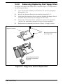
CPU/RAM Subsystem
The Pentium-based notebook runs at a system bus speed of 50 MHz and a
processing clock rate of 75MHz. As a standard feature, the notebook
contains 8MB of 70 ns page-interleaved DRAM and 256KB of 15-ns static
RAM for external cache. DRAM memory can be expanded to 32 MB using
two DRAM Expansion Board options (expansion boards install from the
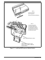
front of the notebook by removing the floppy bezel as shown in Figure 1-9).
c
Caution: The RAM module option contains components that are sensitive to static electricity. When handling the module and the internal
parts of the computer, protect against static electricity by using wrist
or ankle grounding straps and grounded working mats. When moving
or storing items, use the anti-static bags supplied with the items.
The first memory option may be either 8 MB or 16 MB; a second 8 MB board
(Shuttle RAM option) can be installed onto the first expansion module as
shown in Figure 1-9.
1-14 General Description
Up to two RAM Expansion Boards
may be user-installed onto the
Main Board by removing the
Bezel below the Floppy Drive.
8MB or 16MB RAM
Expansion Module
8MB Shuttle RAM Module
Figure 1-9 RAM Expansion Features
As shown in Figure 1-2, the Pentium version of the TM5000 Notebook also
contains a higher performance hard disk subsystem. The IDE hard disk
drive is interfaced to the VL local bus and achieves I/O operations in the 11
million to 14 million operations per second.
1.3.2
ROM Memory
All versions of the TM5000 notebook family use a "Flash" ROM which is a
40-pin TSOP device with "Boot Block" logic that allows for reprogramming of
ROM without destroying its boot capability. The Flash ROM device contains
both the main system BIOS and the VGA BIOS.
General Description 1-15
1.3.3
Hard Disk Subsystem
The TM5000 Notebook family features a user-replaceable, 2.5 inch, (initially
either 810 million byte or 524 million byte capacity) enhanced IDE interface
Hard Disk Drive. Both drives have a 128KB buffer and can transfer data in
or out of the buffer at a 4.5 MB/second rate across the ISA Interface using
the 2 of 7 RLL code recording method.
The hard drive also features built-in power conservation features configured
from the standard CMOS Setup Routine. An Automatic Power Down mode
can be selected which powers down the drive motor during periods of
inactivity. An additional level of power conservation may also be selected
which powers down the motor plus all control circuits.
The hard drives are factory formatted as a single drive (Drive C:) and are
preloaded with software (MS-DOS, Windows and TI Utilities).
In all Pentium-based notebooks, the hard drive is connected to the VL-local
bus for increased performance.
1.3.3.1
Access to Hard Disk Drive
Access to the hard drive is provided through a removable panel on the
bottom of the notebook (removal/replacement instructions for the hard
drive are provided in Section 5).
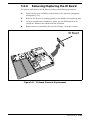
1.3.4
Floppy Diskette Subsystem
The notebook series include a front-mounted, 3.5 inch floppy diskette drive
which is capable of reading/writing 1.44 MB floppy diskettes. An activity
indicator for the floppy drive is located along the front edge of the notebook.
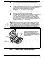
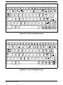
1.3.5
Keyboard Subsystem
The TM5000 Notebook uses an 83-key keyboard (84 keys for international
versions) similar in layout to the TM4000E Notebook Keyboard emulating all
functions of an IBM AT-101/102 keyboard. A Special Function key (Fn
allows some of the TM5000 keyboard keys to take on additional functions
See Figure 1-10).
The keyboard’s 4mm key travel gives the touch and feel of a full-size
workstation keyboard. The Point, which is a pressure-sensitive mouse
device, is embedded in the keyboard. The select switches for the built-in
mouse device are located just below the keyboard.
Some of the major features of the keyboard include:
•
4-mm Key movement
•
Integrated numeric keypad
•
"Inverted T" Cursor Control Key Layout
1-16 General Description
•
•
Special Keys for the following:
•
Setup Menu (Fn-ESC)
•
Standby Mode (Fn-F4)
•
Scroll Lock Mode (Fn-F6)
•
Num Lock Mode (Fn-F7)
•
Real-Time Sound Volume Adjustment (CTRL-ALT-U or
CTRL-ALT-D)
•
Real-Time CPU Speed Adjustment (CTRL-ALT-UP/DOWN
Arrow)
Separate keys for Page Up, Page Down, F11 and F12 plus inverted
"T".
Functionally, the Keyboard Subsystem comprises the following major
circuits:
•
Keyboard Assembly
•
Keyboard Controller (implemented on the Key Scan Board)
•
Bus Interface Logic on the Main Board
Embedded Point Device
83/84 Key, 4mm Keyboard
Special Function Key (Fn)
Point Select Buttons
Figure 1-10 Internal Keyboard for TM5000 Series
General Description 1-17
1.3.6
Video Display Subsystem
The initial offering of the TM5000 Series Notebook Family contains a
built-in TSTN (Triple Super Twist Nematic) active matrix color LCD with
CCFT (Cold Cathode Fluorescent Tube). The LCD has a VGA compatible
resolution of 640 by 480 pixels. All members of the TM5000 family support
simultaneous LCD and external VGA display at 640 x 480 resolution.
At the heart of the notebook’s video subsystem is a powerful video engine,
the Cirrus Logic CL-GD7542 GUI-accelerated Super VGA LCD Controller
with MotionVideo tm implemented on the Main Board. Features of this video
engine include:
•
32-bit Block Transfer Engine with GUI Acceleration
•
640 x 480 LCD support
•
True-color capability
•
Motion-Video architecture with live video overlay
The video subsystem includes a 2 MB RAM memory, 32-bit DRAM bus, and
separate display and memory clocks. An additional frame buffer/accelerator
DRAM increases the available memory band width for CPU accesses. The
video section also uses additional levels of write FIFOs, a read cache, page
mode DRAM and full 32-bit bus access to produce a high performance video
system.
1.3.6.1
High Resolution VESA and Extended Modes
The video engine in the notebook is capable of operating at dot clock rates
programmable up to 85 MHz at 5.0 V or 65 MHz at 3.3 V and supports
standard VGA and VESA high-resolution extended modes at refresh rates
up to 75 MHz. The internal palette can be configured as an
industry-standard RAMDAC to provide a palette of 256K colors or
configured for direct color displays of 32K, and 65K colors.
In addition, the video engine supports the following Super VGA modes:
•
640 x 480 with up to 65K colors on LCD and CRT
•
800 x 600 with up to 65K colors on LCD and CRT
•
1024 x 768 with up to 256 colors on CRT
•
1280 x 1024 with up to 256 colors on CRT (interlaced)
1.3.7
Sound Subsystem
All members of the TM5000 series include a Jazz 16 Sound chip set which
supports stereo digital recording and playback, microphone and line input,
automatic gain control, 20-voice FM music synthesizer, 44.1 Khz audio
recording and playback, built-in file compression/decompression, and
built-in power amplifier with volume control. Jazz 16 software supplied with
the system provides for computer control of all sound features.
1-18 General Description
1.3.8
External Ports
The TM5000 Notebook contains external connectors on the left, right and
rear of the notebook as shown in Figure 1-11. Sound, power and external
keyboard connectors are located on the left side of the notebook; the back of
the unit contains connectors for a parallel printer, external VGA monitor,
serial com, and expansion device such as the EZ-Dock Port Replicator. The
right side of the notebook contains the infrared interface as shown in Figure
1-11.
Audio In (From output of
CD-ROM Player, Tape Player,
Radio, Etc.)
Audio Out (To headphones
or external speakers; disables
internal speaker)
AC Adapter Connector
PS/2 Port- (For connecting
external PS/2 Keyboard, 101
Type Keyboard (With Adapter), PS/2
Mouse or Cable Connect Numeric Keypad
Option)
External Microphone
Input- Disables internal
microphone when external
mic is plugged in.
Infra-Red Interface
15-Pin External
VGA Port
160-pin Expansion Bus
(Connects to docking system option)
9-Pin Serial
Port
25-Pin Parallel
Bi-Directional Port
Figure 1-11 Notebook External Ports
General Description 1-19
1.3.8.1
Bi-Directional Parallel Port
The TM5000 notebooks include a 25-pin Parallel Printer Port with EPP/ECP
bi-directional modes. The parallel port is implemented using a standard
25-pin, female, D-subminiature connector.
1.3.8.2
External VGA Port
The external VGA port is implemented with a high density, 15-pin female,
D-subminiature connector.
n
Note: See Appendix E for additional information regarding supported monitor types.
1.3.8.3
PS/2 Keyboard/Mouse/Numeric Keypad Port
The Notebook is equipped with a 6-pin circular mini-Din connector that may
be used to connect an external PS/2 Mouse, external PS/2 Keyboard (or
101 Keyboard using an adapter), or the PS/2 Numeric Keypad option.
However only one device may be connected to the port.
1.3.8.4
Serial Port
The TM5000 Series Notebooks include a 9-pin, industry standard, RS-232-C
serial (16550 UART) Com port (9-pin, male, D-type connector) as a standard
feature. This port can be used to connect to any external device conforming
to RS-232-C standards.
1.3.8.5
Infrared Interface
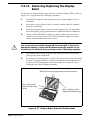
The infrared interface (Figure 1-12), located on the right front area of the
Notebook, contains the serial Infrared transmitters/receivers required to
communicate with an external device containing an industry-standard IRDA
infrared interface (eg. mouse, keyboard, another computer, etc.).
Infrared Interface Port
Figure 1-12 Infrared Interface
1-20 General Description
1.3.8.6
PCI Expansion Bus Interface
The TM5000 Notebook is equipped with a 160-pin PCI expansion bus that
includes the PCI bus, VESA Video Feature interface, MIDI interface, Power
Control and Plug N Play interfaces.
1.4
Notebook Expansion Capabilities
The notebook computer can be equipped with the following field-installable
options:
•
8 MB RAM Expansion Option, P/N 9798816-0001
•
16 MB RAM Expansion Option, P/N 9798816-0002
•
8 MB Shuttle Memory Expansion, P/N 9798816-0003
•
Headset and Microphone Option Kit, P/N 9793399-0001
•
Cable Connect PS/2 Numeric Keypad, P/N 2581381-0001
•
Spare AC Adapter, P/N 9786218-0001
•
External Battery Charger, P/N 9793360-0001
•
Spare Li-Ion Battery Pack Kit, P/N 9786217-0001
•
PCMCIA options
•
14.4KB Data/Send/Receive Fax Modem Option, P/N
9798074-0001
•
Token Ring Option, P/N 9791774-0001
•
Ethernet 10BaseT Twisted Pair Option, P/N 9791773-0001
•
Ethernet 10Base2 Thin Coaxial Cable Option, P/N
9791773-0002
•
Executive Carrying Case, P/N 2567028-0001
•
High Density to High Density SCSI Connector, TI P/N 9794074-0001
•
Third Parity External PS/2 keyboard (or external mouse)
These options are briefly described in the following paragraphs.
1.4.1
Memory Expansion
Three RAM Expansion Option boards are available for the TravelMate 5000
Series including:
•
•
8 MB RAM Module Kit (TI Part No. 9798816-0001)- This kit allows
you to increase RAM memory size from 8 MB to 16 MB.
16 MB RAM Module Kit (TI Part No. 9798816-0002)- This kit allows
you to increase RAM memory size from 8 MB to 24 MB.
General Description 1-21
•
8 MB Shuttle Memory Option Kit (TI Part No. 9798816-0003) - This
Kit installs on one of the other RAM Module options (expands RAM to
32MB if installed on 16MB RAM Option boards)
These RAM expansion kits are user-installed as detailed in Section 2.
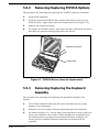
1.4.2
Headset and Microphone Option Kit
The Headset and Microphone Option Kit, Part No. 9793399-0001, contains
an external microphone and set of headphones for use with the multi-media
notebook. When the external devices are installed, the internal microphone
and speaker are disabled.
1.4.3
PS/2 Numeric Keypad Option
The PS/2 Numeric Keypad option, TI P/N 2581381-0001, is available to
support business accounting applications. This option installs on the 6-pin
MINI-DIN connector on the left side of the Notebook. When installed,
numeric data can be entered from the Keypad while the notebook keyboard
remains active.
1.4.4
External Battery Charger
The External Battery Charger option, TI P/N 9793360-0001, permits rapid
charge of the Notebook’s Lithium-Ion battery packs outside of the notebook
environment.
1.4.5
Extra Battery Option
A spare Lithium-Ion battery pack, P/N 9786217-0001, is available to
increase the time the notebook can operate on battery power.
1-22 General Description
1.4.6
Notebook Carrying Case Options
The following carrying cases are available for the TM5000 Notebook
Computer:
•
•
•
Leather Portfolio (TI P/N 2567028-0001) - carries only the notebook
Deluxe Carrying Case (TI P/N 2568069-0001) - carries the notebook
and smaller accessories.
Executive Briefcase (TI P/N 9793372-0001) - a larger carrying case
for the notebook, docking system and accessories.
1.4.7
PCMCIA Card Options
The Notebook contains an onboard PCMCIA Controller (Cirrus CL-GD6720)
and two 64-pin sockets that can accept up to two credit-card size (14.5mm)
Type III or one Type I or II PCMCIA option cards. Some of the options
available from Texas Instruments include:
•
14.4KB Data/Send/Receive Fax Modem Option, P/N 9798074-0001
•
Token Ring Option, P/N 9791774-0001
•
Ethernet 10BaseT Twisted Pair Option, P/N 9791773-0001
•
Ethernet 10Base2 Thin Coaxial Cable Option, P/N 9791773-0002
Other third party PCMCIA options on the market today include hard drives,
flash memory, modems, etc. These options require downloading the
appropriate Phoenix Device Driver software using the PCMCIA
PhoenixCARD Manager software supplied with the Notebook. See manual
in PheonixCard Manager Kit for additional information.
1.5
Standard Test Features
The TravelMate 5000 Series Notebook Computers use modular design and
built-in test features to reduce the mean-time-to-repair. A power on self-test
automatically verifies the operational state of the primary circuits and a
powerful suite of diagnostic tests (known as PC-Doctor) are available to
further test selected parts of the system.
1.5.1
Built-In Self Test
The notebook computer contains a built-in self test that automatically
performs a test of memory and all major circuits each time the computer is
powered up. In the event of a failure, the computer displays a descriptive
error message and issues a series of coded beeps (in case the display
subsystem is not functioning). The coded beeps are listed and described in
Section 4 of this manual.
If self test completes normally, the computer displays the amount of
memory tested and loads the Operating System and Windows environment.
General Description 1-23
1.5.2
Diagnostics Program
The TM5000 Series Notebooks are shipped with PC-Doctor, a powerful
diagnostics tool that determines the hardware configuration of a local or
remote system, benchmarks the system’s performance, analyzes the
performance of all subsystems, and performs a suite of interactive and
non-interactive tests on attached devices (such as printers, joystick devices,
VGA monitors, SCSI devices, CD-ROM drives). The test results are stored in
a log which can be printed out (by pressing F2) or saved in a disk file (by
pressing F3).
Features of the diagnostic program are accessed through a series of
pull-down menus and basic keyboard keys (cursor keys to move highlighted
pointer, Enter key to select a highlighted feature, ESC key to cancel a
function and move back one level.)
PC-Doctor is typically user friendly but if you don’t understand a feature,
context-sensitive "help" information is available at any time by pressing the
F1 function key; pressing the F1 function key twice accesses the online
Technical Reference Manual for PC-Doctor.
A powerful set of utilities within PC-Doctor (that can be run locally or
remotely) simplify the task of determining system configuration data,
allocating and using system memory, IRQ and DMA use, what device drivers
are installed, what COM and LPT ports are assigned and what ports are
available, identifying partitioning data for fixed disk drive(s), determining
the VGA setup information, reading the software interrupts/interrupt
vectors, etc.
n
Note: See Troubleshooting Section for additional information regarding the
Diagnostics Program.
1.6
Product Models
The initial model of the TravelMate 5000 Series, TI Part No. 9798843, is
equipped with a Pentium Processor, 810 million byte (772MB) Hard Drive
and 10.4 inch TFT color display. The unit assembly for this product is
available in one of 15 domestic and international configurations as listed in
Table 1.1.
Table 1-1. TravelMate 5000 Series Notebook Domestic/International
Configurations
Configuration
Dash No.
Domestic Configuration
-0001
UK Configuration
-0002
1-24 General Description
Table 1-1. TravelMate 5000 Series Notebook Domestic/International
Configurations (continued)
Configuration
Dash No.
German Configuration
-0003
French Configuration
-0004
Spanish Configuration
-0005
Swiss/German Configuration
-0006
Italian Configuration
-0007
Portuguese Configuration
-0008
Western European Configuration
-0009
Swedish Configuration
-0010
Swiss/French Configuration
-0011
Danish Configuration
-0012
Norwegian Configuration
-0013
Finish Configuration
-0014
Belgium Configuration
-0015
Austrian Configuration
-0016
Latin American Configuration
-0018
General Description 1-25
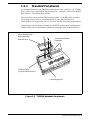
1.7
Notebook Physical Description
The TravelMate 5000 Series Notebooks are modular in design and can be
disassembled for maintenance purposes using a set of TORXTM head,
Phillips head, and straight slot screwdrivers as described in Section 5 of
this manual.
Mechanically, the Notebook Computer consists of two major assemblies
including the Cover-Display Assembly and the System Base Assembly as
shown in Figure 1-13.
Cover-Display
Assembly
System Base Assembly
Figure 1-13 Notebook Major Assemblies
1-26 General Description
1.7.1
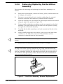
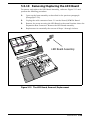
Cover-Display Assembly
The Cover-Display Assembly contains the LCD screen, power inverter
circuits, and associated control circuitry. The assembly, shown in Figure
1-14, contains four major components including:
•
LCD Display
•
Microphone Assembly
•
Inverter Board
•
Display Adapter Board
The Cover-Display Assembly attaches to the System Base Assembly through
seven mounting screws on the bottom of the computer and two screws that
secure the hinges to the Cover-Display Assembly (See Section 5 for
additional detail).
LCD Display Screen
Microphone Assembly
Power Inverter Board
Shown with
Display Bezel
Removed
Display Adapter Board (DAB)
Figure 1-14 Cover Display Assembly FRUs
General Description 1-27
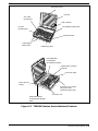
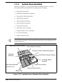
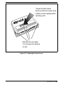
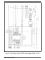
1.7.2
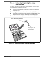
System Base Assembly
As shown in Figure 1-15, the System Base Assembly houses a variety of
field-replaceable subassemblies and components including:
n
•
Main Board Assembly
•
PCMCIA/Sound Board Assembly
•
Sleep Switch Board Assembly
•
LED Board Assembly
•
Infrared Board Assembly
•
Keyscan Board Assembly
•
Keyboard Assembly
•
Hard Disk Drive Assembly
•
Floppy Diskette Drive Assembly
•
The Point Assembly
•
Internal Battery Packs
Note: FRU part numbers and assembly removal/replacement procedures
are provided in Section 5 of this manual. Factory-level parts listings are provided in Section 6.
Sleep Switch Board Assembly
Internal Speaker Assembly
Hard Drive (Under PCMCIA/Sound Board)
LED Board
Assembly
PCMCIA/Sound Board Assembly
IR Interface Board
Assembly
Main Board Assembly
(at base of unit)
Floppy Drive Assembly
Keyscan Board Assembly
Battery Bays
Figure 1-15 Exploded View of Notebook Base Assembly
1-28 General Description
1.8
Notebook Functional Overview
The TravelMate 5000 Series Notebooks consist of eight major functions or
sections including:
•
System Processor- implemented on Main Board
•
Memory Subsystem- implemented on Main Board
•
I/O Subsystem- implemented on Main Board
•
•
Keyboard Subsystem- implemented on part of Main Board, Key Scan
Board, and Keyboard Assembly
Video Subsystem- implemented on Main Board, Display Adapter Board,
and LCD Display
•
Sound Subsystem- implemented on the PCMCIA/Sound Board
•
PCMCIA Adapter and sockets- implemented on PCMCIA/Sound Board
•
•
•
•
Pointing Device Subsystem-implemented on Main Board and Keyboard
Assembly
Hard Disk Subsystem- implemented on Main Board and the Hard Drive
Assembly
Floppy Disk Subsystem- implemented on Main Board and Floppy Drive
Assembly
Power Subsystem- implemented on Power Supply Board, Inverter Board,
battery packs, front panel LEDs, and AC adapter
A simplified block diagram of the computer is shown in Figure 1-16.
General Description 1-29
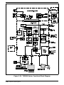
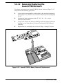
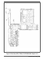
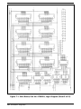
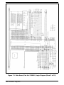
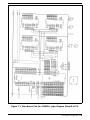
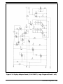
Figure 1-16 TM5000 Series, Functional Block Diagram
1-30 General Description
1.8.1
System Processor
The System Processor function for the notebook is implemented on the Main
Board using an Intel Pentium P54-C Superscalar Processor Chip. The
processor operates in conjunction with RAM and ROM Memory and other
control logic (E.G. the ACC2056 IC) to process software instructions (BIOS,
DOS, Windows, Applications).
The processor communicates with hard disk and the memory components
using a high speed, VL-Local Bus. All other high speed peripheral
components are driven by the 33-MHz PCI Bus.
The PCI Bus Controller Chip (ACC2188) provides the bridge between the
64-bit VL-Local Bus and the 32-bit, 33 MHz Peripheral Components
Interface (PCI) Bus.
The Processor also executes the BatteryPro software and interacts with
other hardware logic to provide the power savings features for the notebook.
These features include controlling CPU clock speeds, reducing clock speeds
whenever possible (eg. when performing floppy drive accesses), powering
down unused devices, etc.
1.8.2
Memory Subsystem
The memory subsystem, implemented on the Main Board, includes ROM
and DRAM memory. Primary control for the memory subsystem is provided
by the ACC2056 Core Logic Chip.
1.8.2.1
DRAM Memory
All Pentium-based notebooks (Intel P54-C CPU) contain 8MB of 70 ns
page-interleaved DRAM and 256KB of 15-ns static RAM for external cache.
DRAM memory on the Pentium versions can be expanded to 32 MB using
two DRAM Expansion Board options. An additional 24 MB may be user
installed using a 16 MB Expansion RAM Module and an 8 MB Shuttle RAM
Expansion Module described in more detail later.
1.8.2.2
ROM Memory
All versions of the TM5000 notebook family use a "Flash" ROM that contains
both the main system BIOS and the VGA BIOS. The Flash ROM contains
"Boot Block" logic that allows downloading new versions of BIOS without
destroying the Boot Load area.
General Description 1-31
1.8.3
I/O Subsystem
The I/O ASIC on the Main Board and an SMC 37C665 GT Combo I/O
Controller Chip control all "AT"-type I/O peripherals. Two cascaded DMA
controllers and two cascaded interrupt processors on the I/O ASIC support
transfers between memory and the 8-bit and 16-bit peripherals (via the
Combo Controller). The supported I/O interfaces include:
•
•
•
•
•
•
Internal Hard Disk Drive Interface - Provides control information and
data exchange (via an integrated drive electronics (IDE)-type interface)
between the computer and the system disk drive.
Internal Floppy Diskette Drive Interface - Provides control and data
exchange between the computer and the 3.5 inch floppy diskette drive.
Internal Pointing Device Interface- internal controller that interfaces the
built-in pointing device with the system processor.
External Parallel Bi-Directional/ECP/EPP Compatible Interface Provides control information and data exchange between the computer
and external parallel peripheral devices via an external DB-25 Port (this
port is configured from the Setup program). The parallel port is
compatible with the port used in the PC-AT but also features the PS/2
like extended mode for bi-directional EPP/ECP operations.
External Serial Port Interface- includes a 16550-compatible UART that
drives an external RS-232 port (configured from the Setup Program).
External PS/2 Keyboard/Mouse Port- six-pin Mini-DIN connector on the
rear of the Notebook which can attach to either an external PS/2
keyboard (or 101 keyboard with adapter), external PS/2 type mouse, or
external numeric keypad (only one of the three device types may
connect to the 6-pin connector).
1.8.4
AT Peripherals Subsystem
The interface between the system processor and the Floppy and Serial and
Parallel ports is provided by the FDC37C665GT combination controller.
1.8.5
Video Subsystem
The video subsystem, implemented on the Main Board and on the LCD
Display Unit, displays text, graphics and drives an external VGA port.
The video subsystem includes 2 MB RAM memory, 32-bit DRAM bus, and
separate display and memory clocks. An additional frame buffer/accelerator
DRAM increases the available memory bandwidth for CPU accesses. The
video section also uses additional levels of write FIFOs, a read cache, page
mode DRAM and full 32-bit bus access to produce a high performance video
system.
The CL-GD7542 video controller chip used in the TM5000 Notebooks also
supports multi-media capabilities using the MotionVideo tm Architecture
(MVATM). This feature permits integrating video clips or live video. In
1-32 General Description
addition to powerful multi-media capabilities, the video controller offers full
hardware and BIOS compatibility with the IBM VGA standard.
1.8.6
External VGA Capability
All members of the TM5000 notebook family provide a 15-pin, female,
D-type, external VGA connector that can be connected to an external video
graphics adapter (VGA) type monitor.
Another feature of the notebook computer is the ability to provide both an
LCD display and simultaneously drive an external CRT (standard VGA
modes) with resolution of 640 X 480 X 256.
1.8.7
Sound Subsystem
The TravelMate 5000 Series Notebook is equipped with the Media-Vision
Jazz tm 16 chip set that is Sound Blaster tm and Sound Blaster Pro tm
compatible. An internal speaker and microphone provide the Notebook with
direct sound generation and recording capabilities. A set of 3.5 mm bayonet
socket connectors allow for external microphone and line inputs and
headphone outputs.
A MIDI adapter cable option permits attaching musical instruments (with
digital interface) to the notebook via the EZ-Dock Plus Port Replicator option.
The sound subsystem also includes a variety of Window’s-based
multi-media software and DOS Utilities that combine to provide the
following multi-media functions:
•
•
•
Digital audio recording and playback
Audio mixing- can mix five audio sources for playback (MIDI, CD-ROM,
Line In, playback waveform files and a microphone). Can mix three
sources for recording (CD-Player, Line In and Microphone)
20 voice FM music synthesizer (plays up to 20 instruments
simultaneously to deliver an orchestra of stereo sound)
General Description 1-33
1.8.8
Pointing Device Subsystem
The pointing device subsystem (Figure 1-17) consists of the built-in "Point"
device on the keyboard and a pre-programmed 82c752 micro-controller that
interfaces the mouse device to the main board. An external PS/2 port also
supports the use of an external PS/2 compatible mouse.
Embedded Point Device
83/84 Key , 4mm Keyboard
Select Switches
Figure 1-17 Notebook Pointing Device
1.8.9
Keyboard Subsystem
The keyboard subsystem is implemented on the keyboard assembly,
Keyscan Board, and part of the System Board.
The TravelMate 5000 Series Keyboard, shown in Figure 1-18, is an
83/84-key, IBM enhanced-type keyboard with the standard character and
function keys plus 12 programmable function keys (F1 through F12).
Using the Special Function (Fn) key which assigns multiple functions to
keys, the keyboard can emulate the IBM 101/102 keyboards using 83 keys
(84 on international models).
The keyboard has a 4mm stroke and features a special keyboard interface
chip that can detect multiple levels of key input (good simulation of N-key
rollover for up to 10 keys).
Some of the major features of the keyboard include:
•
4-mm Key movement
1-34 General Description
•
Integrated numeric keypad
•
"Inverted T" Cursor Control Key Layout
•
Special Keys for the following:
•
•
Setup Menu (Fn-ESC)
•
Standby Mode (Fn-F4)
•
Real-Time Sound Volume Adjustment (CTRL-ALT-U or
CTRL-ALT-D)
•
Real-Time CPU Speed Adjustment (CTRL-ALT-UP/DOWN
Arrow)
Separate keys for Page Up, Page Down, F11 and F12 plus inverted "T".
The notebook keyboard is available in the following versions:
•
U.S. English- This version (also known as the domestic version) has 83
keys and is generally used in the United States and Canada.
•
n
n
U.K. English- This version (also known as the international version) has
84 keys and is generally used in England, Germany, and other
European countries with the appropriate keycap changes.
Note: See Appendix B for international keyboard layouts
Note: The TravelMate 5000 Series Notebook Computer User’s Online Reference Manual provides detailed descriptions of keyboard special function keys.
A six-pin Mini-DIN connector on the left side of the Notebook can attach to
either an external PS/2 keyboard (or 101 Keyboard via an adapter), PS/2
Mouse, or the optional PS/2 Numeric Keypad.
Esc
Set Up
F1
F2
F4
F3
F5
F6
F7
F8
&
7
%
1
2
A
Shift
Fn
S
Ctrl
Alt
R
T
F
D
X
Z
6
5
E
W
Q
Caps
Lock
4
3
C
8
U
4
J
N
F12
9
(
I
1
M
Prt Sc
SysRq
Pause
Break
Del
Ins
0
5
K
NumLk
Scr Lk
)
9
8
H
B
F11
7
Y
G
V
F10
F9
O
2
0
6
L
P
Enter
3
0
Alt
Enter
Enter
Home
Shift
End
PgUp
PgDn
Figure 1-18 Keyboard Layout
General Description 1-35
1.8.9.1
LED Displays
As shown in Figure 1-19, the TravelMate 5000 Series Notebook Computers
contain a set of three LED displays just above the keyboard including:
•
•
•
Caps Lock indicator. This LED indicates that the keyboard is locked in
the uppercase mode. To switch to the lowercase mode, press the Caps
Lock key.
Num Lock indicator. This LED lights when you press the Fn-F7
(NumLk) keys to toggle on the numeric keypad lock function. When the
LED is On, the embedded numeric keyboard keys generate AT-keypad
characters and functions when pressed in conjunction with the Fn key.
When the indicator is Off, pressing the Fn key with the appropriate keys
provides cursor movement, paging and other functions in the normal
mode. When the indicator is blinking, the embedded numeric keypad
becomes a temporary numeric keypad that does not require you to
press any other key.
Scroll Lock indicator. This LED lights to indicate that the keyboard is
locked in the scroll mode.
Two additional indicators are visible with the notebook open or closed.
These include:
•
Power/Standby Indicator. This is a dual-color LED that glows green
when the Power switch is set to the On position. If the LED does not
come on, the AC adaptor may not be connected or the batteries may be
discharged.
This same LED also glows amber when the computer is set to the Suspend
mode and alternately glows amber and green when the computer enters the
Auto Suspend Mode.
•
Low Batt indicator. This LED glows red (and the alarm sounds if
enabled using the Setup Program) to warn of an impending low battery
condition (approximately 1 to 10 minutes of charge remaining in
battery). Both the alarm and indicator remain on until the computer
shuts itself down.
Three additional LEDs are located along the front panel of the notebook.
These include:
•
•
•
Floppy Disk indicator. This LED indicates the computer is reading from
or writing to the floppy diskette drive.
Hard Disk indicator. This LED indicates system disk drive activity, such
as when the computer is writing to or reading from the drive.
Turbo Indicator. This LED lights when the computer is operating in its
high speed mode. The LED extinguishes during reduced speed
operations, when the notebook is in Standby mode, or when accessing
the Floppy Drive and the Auto Speed mode is active.
1-36 General Description
SCR (Scroll Lock)
PCMCIA Release Switches
NUM (Numeric Lock)
CAP (Caps Lock)
Suspend Button
Power Switch
Battery Release
Switches
The Point
Power/Standby
Indicator
Floppy Diskette
Activity Indicator
Turbo Mode Indicator
Hard Disk
Activity Indicator
Low Battery Indicator
Rear Connector Doors
Release Button
Figure 1-19 Notebook Controls/Indicators
1.8.10 Hard Disk Subsystem
The Hard Disk Subsystem, implemented on the Main Board and on the
associated hard disk drive module, provides disk storage for all system
software and user files.
Depending on the model, the notebook is equipped with an 810 million byte,
1/2" hard drive or other high capacity drive. The disk controller for all
models is a Combo SMC 37C665 chip, which is IDE interface compatible.
During the manufacturing process, Texas Instruments formats the hard
disk and then loads all supplied software (DOS operating system, Windows,
application programs, diagnostics and utilities). A diskette supplied with the
system contains a program that simplifies the process of backing
up/restoring all system software.
General Description 1-37
c
Caution: Formatting the disk drive erases any data that may be stored
on the disk. Therefore do not attempt a format of the hard disk unless
the computer self-test and diagnostics confirm that the disk has not
been formatted.
A Hard Drive activity LED is located along the front edge of the notebook
(See Figure 1-19). This LED lights during hard drive read/write accesses.
c
Caution: The notebook should not be moved when the HDD LED is lit
to prevent accidental damage to the hard drive.
1.8.11 Floppy Diskette Drive Subsystem
The Floppy Diskette Drive Subsystem consists of a Floppy Controller (part of
the Combo SMC 37C665 chip) and the Floppy Diskette Drive.
The Floppy Diskette Drive can read/write standard 3.5-inch minidiskettes
(1.44MB capacity).
A Floppy Drive activity LED, located on the front edge of the notebook, lights
during floppy read/write accesses.
1.8.12 Power Subsystem
Each battery pack contains four green LEDs to display charge status of the
pack (when the Display Charge Status button is pressed on the front of the
battery pack). The four LEDs indicate the percent of charge on the batteries
as shown in Figure 1-4.
The Battery Low Indicator on the top case (Figure 1-19) glows amber when
the batteries are low and is off when the batteries are more than 10%
charged.
As long as one battery pack has sufficient charge (25% or more) to operate
the system, the remaining battery pack may be removed with the notebook
operational (in Suspend mode).
Functionally, the Power Subsystem consists of the following major sections:
•
AC Power Adapter
•
Two Internal Battery Packs
•
NVRAM Battery (on Main Board)
•
Power Supply Section (on Main Board)
•
Inverter Board Assembly (in Cover/Display Assembly).
•
Power Conservation Logic (part of Main Board)
1-38 General Description
1.8.12.1 AC Power Adapter
The computer is equipped with a universal AC power adapter that converts
AC voltage (100 to 240 VAC, 50 to 60 Hz) into DC voltage used to operate
the notebook and charge the batteries. The adapter also supplies sufficient
power to drive an attached EZ-Dock or EZ-Dock Plus Port Replicator option
that may be attached to the notebook.
1.8.12.2 Intelligent Battery Packs
The TM5000 Series Notebooks hold up to two intelligent battery packs
(Lithium-Ion) as shown in Figure 1-4. Each intelligent battery pack contains
circuitry to monitor the charge remaining in the pack and recharge the pack
when the AC Adapter is present.
The rechargeable battery packs provide DC power for the computer (and for
the NVRAM and real time clock battery on the Main Board) when the AC
Adapter is not being used.
Each battery pack contain four LEDs to display charge status of the pack
(either when the Display Charge Status button is pressed on the front of the
battery pack or when the batteries are being charged). The four LEDs
indicate the percent of charge on the batteries as shown in Figure 1-4.
As long as one battery pack has sufficient charge (25% or more) to operate
the system, the remaining battery pack may be removed with the notebook
operational (in Standby mode).
To remove a battery pack from the notebook while the notebook is powered
off, press the Battery Eject Button (just above the top left side of the
keyboard) and remove the pack from the front of the notebook. If the
batteries are not totally discharged, you can replace a battery pack with the
system operational (in Suspend Mode) without loosing data. Insert a
charged pack back into the system. Repeat the procedure with the
remaining pack if you have a second replacement battery.
1.8.12.3 NVRAM Battery
The Main Board in the notebook is equipped with a smaller 3.6V, 11 MAH
(milli amphere hours) Nickel Metal Hydride battery which drives the battery
powered CMOS memory (non-volatile memory) and real time clock when the
main batteries are out of the notebook. The NVRAM battery is recharged
from the Vcc supply when the notebook is operating off battery power or
from the AC adapter when attached even if the notebook is powered off.
1.8.12.4 Power Supply Section of Main Board
The Power Supply Section receives approximately 7.2 VDC from the battery
packs and uses this input voltage to generate +3, +5 and +12 regulated
output voltages to provide power for all internal notebook board assemblies.
The output of the +5 volt regulator also drives the LCD inverter circuit on
the Inverter Board Assembly (part of the Cover-Display Assembly)..
General Description 1-39
The outputs of the Power Supply Section include:
•
+3 VDC at 3 Amps
•
+5 VDC at 5 Amps
•
+12 VDC at 60 Milliamps (Flash memory)
1.8.12.5 Inverter Board Assembly
The Inverter Board Assembly, located in the Cover Display Assembly,
converts the +5 VDC input from the Power Supply Section of the Main
Board into a high voltage AC output used to light the CCFT.
1-40 General Description
1.9
TravelMate 5000 Series
Notebook Specifications
Specifications for the TravelMate 5000 Series Notebooks are provided in
Table 1-2.
Table 1-2 TravelMate 5000 Series Notebook Specifications
Functional Characteristics
Characteristics
Specification
Processor
Pentium Model
Intel P54-C, 75 MHz clock rate; 3.3-volt
Memory Subsystem
ROM:
RAM:
2 MB FLASH ROM, Boot Block logic
8 MB RAM Standard; User Expandable to 32 MB
Hard Drive:
Disk Storage Capacity: 810 million bytes (772MB)
Disk Size:
2.5 inches (63.4 mm)
Floppy Drive:
Diskette Size
Diskette Storage
Capacity
3.5 inches (88.8 mm)
1.44 MB
Display:
Type:
Resolution:
Lines/Screen:
Colors:
Video Memory:
10.4 Inch Active Matrix Color
640 X 480 pixels bit-mapped
25
up to 65K colors
2 MByte
Layout:
"Inverted T" Cursor Control Key Layout
Function Keys:
F1 to F12
Sound Features
Full Sound Blaster and Sound Blaster Pro Compatability
MPU-401 UART Mode compatible MIDI/Joystick port (when
using EZ-Dock Plus option)
Built-in power amplifier with volume control
Built-in 2:1, 3:1, and 4:1 compression/decompression for 8-bit
PCM files in both stereo and mono sample
44.1 khz digitized audio playback using 16-bit Digital to
Analog Converter
44.1 khz digitized audio recording; records any kind of sound
input from microphone or line inputs
20-voice FM music synthesizer-plays up to 20 instruments
simultaneously to deliver an orchestra of music.
General Description 1-41
Table 1-2 TravelMate 5000 Series Notebook Specifications (continued)
External Interfaces
Characteristics
Specification
Serial Port
Connector Type:
Transmission Type:
Bits per second:
Line control:
Data Word
9-pin, male, D-type connector
Asynchronous transmission
110, 200, 300, 600, 1200, 2400, 4800, 9600, 19200
READY/BUSY, DC1/DC3
7 or 8 bit
CRT Monitor Interface
15-Pin Female, D-Type Connector (See Appendix E for
Description of Supported Monitors.)
PS/2 Keyboard/
Mouse Interface
6-pin Mini-DIN Connector
Expansion Bus
Interface
160-pin connector for I/O Expansion; includes full PCI bus
with sidebands
Parallel Printer Port
Type:
Modes:
Bi-Directional
ECP/EPP Compatible
PCMCIA Support
Features:
Two 68-pin sockets for One Type III or two Type I/II Cards;
Supports 3V, 5V, and 12V Cards.
Driver/Configuration
Software:
PhoenixCARD MANAGER Plus
Power Subsystem
AC adapter:
Input Voltage:
Input Current:
Input Frequency:
Output Voltage:
100 to 250 VAC
0.7 to 0.4 Amps
50 to 60 Hz
+9.0 Vdc to +18Vdc
Software
Productivity Utilities:
Laptop File Management System, Drop-N-Go Utility, WinMode
Video Utility, Advanced BatteryPro Power Management,
Password for files security, Change Cursor Utility, set of
memory management drivers that increase system speed and
performance and Backup/Restore Utilities and advanced
diagnostics for system maintenance Utility
Sound Software:
Jazz 16 Software Utilities
1-42 General Description
Table 1-2 TravelMate 5000 Series Notebook Specifications (continued)
Physical Characteristics
Width:,
Depth:
Height:
Weight:
11 inches (27.9 cm)
8.5 inches (21.6 cm)
2.2 inches (5.6 cm)
6.7 pounds (2.9 kg) with two Lithium-Ion Battery Packs
Environmental Characteristics
Operational
Temperature:
Altitude:
Vibration:
Shock:
Humidity:
Non-Operating
Temperature:
Altitude:
Shock:
Vibration:
50° F to 95° F (10° C to 35° C)
8200 ft (2500 m) maximum
Derate linearly the maximum temperature by 4 degrees F per
1000 ft of altitude over 2500 ft (2.2 C per 305 m over 762 m)
0.5G, 20 to 500 Hz; .06mm, 5 to 20 Hz
10G applied in 6-orientations (pos. and neg. X, Y, and Z axis)
20% to 80% (non-condensing)
-4 degrees F to 140 degrees F (-20 degrees C to 60 degrees C
49,000 ft (15000 m)
60G applied in X and Y axes: 35G in Z axis
5.0 G peak, 20-500 Hz; .06mm, 5 to 20 Hz
Agency Approvals
All TM5000 Series
products meet the
following standards:
Safety:
UL 1950 2nd Edition, Underwriters Laboratories Inc.
CAN/CSA-C22.2 No. 950-M89; Underwriters Laboratories Inc.
EN 60950 2nd Edition; TUV Rhienland of North America.
IEC950 EMKO-TSE (74-SEC) 207/94; NEMKO
RFI EMI Interference:
CFR47, Part 15, Subpart B, Level B
Canadian DOC Level B
EN 55022/CISPR-22. Level B
VDE 0878, Part 3 and Part 30
Agency Approval
Markings:
FCC CFR 47 Part 15, Subpart B, Class B Certification
NEMKO EN55022 Class B Certification
VDE VDE0878 Part 3 and Part 30 Self Declaration with BZT
General Description 1-43
2
Installation
2.1
Introduction
This section contains unpacking and preparation for use instructions for
the TM5000 Series Notebook Computers. This includes:
•
Removing the computer and all manuals, options and accessories from
the shipping container(s) (Paragraph 2.2)
•
Installing Internal Notebook Options (Paragraph 2.3)
•
Installing External Notebook Options (Paragraph 2.4)
•
Installing Battery Packs (Paragraph 2.5)
•
Installing Desktop Devices (Paragraph 2.6)
•
Installing the AC Adapter (Paragraph 2.7)
•
Checking Out the System (Paragraph 2.8)
•
Configuring the System (Paragraph 2.9)
•
Making Backups of System Software (Paragraph 2.10)
•
Loading Application Software (Paragraph 2.11)
•
Securing Notebook to Workstation (Paragraph 2.12)
2.2
Unpacking Instructions
The packaging diagram for the notebook computer is shown in Figures 2-1
and 2-2. Unpack the computer using the following instructions:
n
1.
Carefully cut the tape that seals the top flap of the shipping carton.
2.
Remove the computer and the accessories Carton from the main shipping
carton (See Figure 2-1).
3.
Remove all protective coverings from the computer.
4.
Remove the holding tape and open up the accessory box; remove the
contents.
Note: Save the two shipping containers and packaging for later reuse.
Installation 2-1
Software License
agreement
Battery Pack
Filler
End
Caps
TM5000
Pack Box
TM5000
Handle
TM5000
Notebook
Computer
Overpack
Box
Figure 2-1 TM5000 Series Notebook Packaging Diagram
2-2 Installation
TM5000 User's Guide
Domestic
Power
Warranty
Cord
Recovery
Diskette
TM5000
TravelMate
Safety
Passport
AC Adapter
Instructions
QuickStart
Pointing Stick
Cap Kit
PhoenixCard
Manager
Kit
TM5000 User's
Reference
Manual
Accessory Pack
Lithium-Ion
Box
Batteries
Certificate of
Authenticity
MS DOS/WIN
Manual Kit
Figure 2-2 TM5000 Series Accessory Kit Packaging
Diagram
2.3
Installing Internal Notebook
Options
If you have no internal options to install at this time, skip to Paragraph 2.4.
Otherwise, continue with Paragraph 2.3.1.
2.3.1
n
Installing RAM Expansion (Optional)
Note: If not installing RAM Expansion option at this time, skip to the next
paragraph.
Three versions of the RAM Expansion Module option are available including
the 8 MB expansion board (P/N 9798816-0001), 16 MB expansion board
(P/N 9798816-0002), and an 8 MB Shuttle Memory Expansion (P/N
97988816-0003). The Shuttle Expansion Board allows installation of two
memory option expansion modules by attaching to either the 8 MB or 16
MB Expansion Boards.
Installation 2-3
The installation process consists of the following steps:
c
Caution: The RAM module option contains components that are sensitive to static electricity. When handling the module and the internal
parts of the computer, protect against static electricity by using wrist
or ankle grounding straps and grounded working mats. When moving
or storing items, use the anti-static bags supplied with the items.
1.
Turn off the Quick Boot in the System Setup (See TM5000 User’s Guide).
2.
Ensure that the notebook is powered off and the AC Adapter
disconnected from the AC outlet. Also ensure that the batteries are
out of the unit.
3.
Remove the RAM module(s) from its shipping container.
4.
If installing a shuttle RAM expansion module (Shuttle Module), plug the
shuttle module onto the first module as shown in Figure 2-3.
Otherwise, skip this step.
5.
Turn the Notebook upside down on a padded surface.
6.
Remove the holding screws and remove the floppy bezel from the right
front of the notebook (area around the floppy drive as shown in Figure
2-3).
7.
Insert the RAM expansion card such that its two connectors are
aligned with the corresponding connectors in the Notebook’s RAM
expansion area. Plug the board in securely.
8.
Replace the Floppy bezel and secure in place with the screws previously
removed. Replace the AC adapter and power on the notebook.
9.
Power up the notebook and reboot. If all of the installed memory is not
recognized, try reseating the Expansion RAM module(s) and
rebooting. You can now turn on Quick Boot so that you don’t have to
go through a memory check each time you boot.
This completes the RAM Module installation procedure.
2-4 Installation
STEP 1:
Remove Front Bezel
Below Floppy Drive
(Remove two Screws from Bottom)
STEP 2:
If installing Shuttle RAM,
Insert Shuttle RAM Module
onto RAM Expansion Module.
Insert RAM Expansion Module
into Main Board and replace the
Front Bezel (See Above).
8MB or 16MB RAM Expansion Option
8MB Shuttle RAM Expansion Option
Installs on either an 8MB or 16MB RAM
Expansion Module.
Figure 2-3 Installing RAM Expansion Module (Option)
Installation 2-5
2.3.2
Installing PCMCIA Options
The Notebook has two connector slots for PCMCIA option cards. These two
slots can be used to install one type III or two type I/II credit card size
PCMCIA option cards. Install the PCMCIA options as follows:
n
1.
Review the installation instructions supplied with the PCMCIA option
card(s).
2.
Hold the card at the end opposite the connector pins with the label side
up. Insert the card into an unused slot on the right side of the
Notebook.
3.
If the option requires external cabling (e.g. Modem option), connect
external cabling at this time.
Note : After installation or removal of PCMCIA option cards, you must run
the Phoenix PCMCIA PhoenixCARD Manager install software supplied on
hard disk to properly configure the PCMCIA card.
Telephone Jack Connection
(PCMCIA Modem Option)
(XJACK PCMCIA Option Shown)
Figure 2-4 Installing PCMCIA Options
2-6 Installation
2.4
2.4.1
Installing External Notebook
Options
Installing the Optional Numeric
Keypad
An optional numeric keyboard can be attached to the notebook via the
keyboard connector as shown in Figure 2-5.
n
Note: To install option, power off the notebook. Then power the unit back
on after the installation is completed
External Numeric Keypad
Option
Figure 2-5 Installing the Optional PS/2 Numeric Keypad
Installation 2-7
2.4.2
Installing External Mic and
Headphone Kit Option
Figure 2-6 shows the recommended installation of the External Microphone
and Headset Kit onto the notebook.
n
Note: Before installing external microphone and headphones, turn off
power to the notebook.
External Microphone
(disables internal Mic)
External Headset
(disables internal speaker)
Figure 2-6 Installing the External Microphone and
Headphone Kit Option
2-8 Installation
2.4.3
n
Installing the EZ-Dock /EZ-Dock Plus
Port Replicator (Option)
Note: Skip this paragraph if not installing a port replicator option at this
time.
The optional Port Replicator is installed as follows:
1.
Remove the port replicator and any accessories from its shipping carton .
2.
Disconnect the AC Adapter from the notebook (if attached).
3.
Clear an area on your workstation surface to permit the notebook and
Port Replicator to rest on the work surface during the docking
procedure.
4.
Press the rear connector door release button on the rear of the notebook
as shown in Figure 2-7.
5.
Attach the port replicator to the notebook as shown in Figure 2-8 and
described in following steps.
6.
Lift the lever on top of the Port Replicator so that the guide pin plate is
extended (see Figure 2-8).
7.
Carefully match the holes on the underside of the notebook with guide
pins portruding from the Port Replicator.
8.
Press the lever on top of the Port Replicator so that the notebook fits
snugly against the Port Replicator.
9.
Refer to Figure 1-8 for Port Replicator connector assignments. Install
additional desktop devices/LANs/etc. as required.
10.
Install the AC Power Adapter to the power connector on the Port
Replicator as shown Figure 2-8.
Rear Cover Doors
Release Button
Figure 2-7 Opening the Notebook Connector Covers
Installation 2-9
Adapter Connections for
a Docked Notebook
Figure
2-8 Installing
the EZ-Dock Port Replicator/Plus
Figure
2-8 Installing
the EZ-Dock/EZ-Dock
Plus Port Replicator
2-10 Installation
2.5
Removing/Installing Battery
Packs
As shown in Figure 2-9, the TM5000 Notebook has provisions for two
Lithium-Ion battery packs.
Battery Pack Removal
1.
If one of the two batteries contains a partial charge (at least one LED lit
on the front of the battery), the remaining battery pack can be
removed with the Notebook in Suspend. Otherwise, power down the
notebook before removing battery packs.
2.
Slide the battery release button and remove the selected battery as
shown in Figure 2-9.
Battery Pack Installation
1.
Remove battery pack fillers, if installed, by sliding the Battery Eject
switches.
2.
Insert battery packs with the LED indicators facing outward.
3.
Press inwards until pack clicks into place.
Battery Eject Switches
Dual Intelligent
Battery Packs
Figure 2-9 Battery Pack Removal/Replacement
Installation 2-11
2.6
Installing Desktop Devices
When using a port replicator or docking system, all external devices connect
to the docking system as shown in Figure 1-8. Otherwise, all external
devices connect to the Notebook via the connectors on the rear and sides of
the notebook as shown Figure 2-10. Device installation procedures and
connector pin outs are described in the following paragraphs.
Audio In
Audio Out
AC Adapter
Connector
PS/2 Port
External Microphone
Input
Infra-Red
Interface
160-pin Expansion Bus
15-pin External
PCMCIA Slots
9-Pin
Serial Port
VGA Port
25-Pin Parallel
Bi-Directional Port
Figure 2-10 Notebook Computer External Ports
2-12 Installation
2.6.1
Installing an External
Keyboard/Mouse/Keypad
A PS/2 compatible Keyboard, mouse or an optional PS/2 Compatible
numeric keypad may be installed on the Notebook via the mouse connector
on the left side of the Notebook. The connector pinouts are shown in Figure
2-11.
Figure
Port
Figure2-11
2-11 External
ExternalKeyboard/Mouse/Keypad
Mouse/Numeric Keypad Port
Connnector Pinouts
Installation 2-13
2.6.2
Installing External Parallel Printer
The Notebook is equipped with an external, bi-directional, ECC/EPP
compatible, 25-pin parallel printer port. The connector pinouts and
connector location are shown in Figure 2-12.
Figure 2-12 Parallel Printer Connector Pinouts
2-14 Installation
2.6.3
Installing External Serial Port Device
The notebook contains an external RS-232 serial port with a male DB-9
connector as shown in Figure 2-13. The serial ports are used to
interconnect such devices as:
c
•
External Modem
•
Serial Printer
•
Any device that uses an RS-232 interface
Caution: Never connect a parallel device to a serial port or a serial device to a parallel port or video port; this may cause damage to the notebook and/or external device. If you are uncertain of what type
connector the external device has, refer to the technical manual for the
external device.
Figure 2-13 Serial Port Pinouts
Installation 2-15
2.6.4
Installing External VGA Monitor
The notebook is capable of driving both its internal LCD display and an
external VGA monitor (LCD only, simultaneous, or CRT only). The external
monitor connector pinouts and connector locations are shown in Figure
2-14.
To install an external monitor:
1.
Turn off power to both the notebook and monitor.
2.
Connect the 15-pin external VGA cable from the monitor to the VGA
connector.
3.
Power up the computer first; the turn on power to the monitor.
4.
Setup for LCD only, simultaneous LCD and external monitor or external
monitor only using SystemSetup or the WinMode Utility in Windows.
You can also use the VGA utility under DOS.
Figure 2-14 External VGA Monitor Connector Pinouts
2-16 Installation
2.6.5
Installing External
Headphone/Microphones
The notebook connectors used for installing a set of external headphones (or
speakers) and an external microphone are shown in Figure 2-15.
n
Note: When external devices are connected to the Audio Out and Microphone In connectors, the internal speaker and microphone are disabled.
The notebook also has an Audio In connector for attaching a CD-ROM
player, Tape Player or Radio to the notebook (Figure 2-15).
Audio In (From output of
CD-ROM Player, Tape Player,
Radio, Etc.)
Audio Out (To headphones
or external speakers; disables
internal speaker)
External Microphone
Input- Disables internal
microphone when external
mic is plugged in.
Figure 2-15 Notebook Audio Connectors
Installation 2-17
2.6.6
Installing Devices With IR Interface
Any device with an Infrared interface conforming to IRDA specifications may
be placed adjacent to the IR connector on the notebook (two IR interfaces
must face each other) as shown in Figure 2-16.
Note: Any device equipped with Infra-Red interface
conforming to IRDA Specifications may be placed adjacent to the
IR Interface on the Notebook (line of sight).
Infra-Red
Interfaces
SPECIFICATIONS
Range:
Angle:
Wavelength:
Backlight envir:
Line of sight:
Comm Parameters:
Modes Supported:
6 inches to 3 feet
+/- 15 degrees
875 nm
Typical indoor environment
Bi-directional, half duplex
115Kbaud, 8 data bits, odd/even/no
Parity, stop bit.
Infra Red Data Assn. (IrDA);
Hewlett-Packard (HPSIR)
Figure 2-16 Installing Devices with Infrared Interface
2-18 Installation
2.7
Installing the AC Power Adapter
Use the following procedures to connect the AC Adapter to the system:
c
Caution: Use only the AC Adapter supplied with the computer; other
adapters can damage the unit.
1.
Remove the AC adapter from the packaging. Connect the round coaxial
connector supplied with the notebook to the DC IN power receptacle
on the left rear of the notebook as shown in Figure 2-17.
2.
Connect the female side of the AC Power cord to the AC Adapter and
connect the male end to a grounded AC outlet.
Notebook without Port Replicator
Attaching AC Adapter to Docked Notebook
Figure 2-17 Installing the AC Adapter
Installation 2-19
2.8
Initial System Checkout
After you’ve installed all internal options and external cabling, you’re ready
for system checkout and software configuration.
To check out the system, set the power switch on the notebook to the On (I)
position which initiates the notebook self test. During self test execution,
the computer checks the operation of all key hardware including memory
and CPU (and displays copyright and version number data during test
execution).
Upon successful conclusion of self test, the computer automatically loads its
operating system and windows environment. If self test fails to complete and
an error message is displayed, try powering down the computer for a couple
of minutes and turning power back on to repeat self test. If the error
message persists, see Section 4 for troubleshooting information.
2.9
Configuring the System
The first time you power up the notebook, it automatically runs the Setup
Program which prompts you for country name and printer type. You exit
Windows and the notebook begins unzipping files and preparing the
software for use.
Thereafter, you automatically boot to the Startup menu each time you power
up the system. You can also access the Setup program at any time by
simultaneously pressing the Fn and Esc keys. From the Windows
environment, you can also access the Setup Program by selecting the TI
Setup icon in the Notebook Group.
n
Note: When making changes to Setup from Windows, you may need to restart Windows.
If you install one or more PCMCIA option cards, you must also run PCMCIA
PhoenixCARD Manager Plus software or reboot the notebook for the changes
to take affect.
2-20 Installation
2.10 Making Backups of System
Software
The Notebook is preloaded with the DOS/Windows operating system
software, Jazz 16 Sound Utilities, PCMCIA drivers, BatteryPro Software, and
other configuration software.
Supplied with your system is a diskette containing backup and restore
utilities, tools and diagnostics. Prior to extended use of the notebook, create
a backup set of system software using the Backup Utility from the Startup
menu or the Disk Maker Utility in Windows (during the backup process, you
will be prompted to insert a number of blank pre-formatted diskettes). In
the event of a disk problem, you can restore your system using the Restore
Utility on the diskette and the set of backup diskettes you’ve just created.
n
Note: At initial release, full backup requires 22 diskettes for domestic units,
23 diskettes for international units. A complete set of notebook software on
3-1/2" diskettes may also be purchased from Texas Instruments by sending
in the Software Fulfillment Card.
2.11 Loading Application Software
For assistance in loading Application Software, refer to the TravelMate 5000
Online User’s Technical Reference Manual.
2.12 Securing Notebook to
Workstation
The notebook is equipped with a steel security ring that may be cabled
connected to your workstation. As shown in figure 2-18, the security ring is
located on the right side of the notebook. Release the ring using a thin
sharp instrument as shown in Figure 2-18. Then attach an anchored
security cable to the notebook.
Figure 2-18 Notebook Security Ring
Installation 2-21
3
Operating Instructions
3.1
Introduction
The first two subsections describe the TM5000 Notebook operating controls
and indicators. The remainder of this section contains a summary of
computer operations related to notebook maintenance including how to
restore system software.
n
Note: For additional operating instructions, see TravelMate 5000 Series
Notebook Computer Users Guide, TI Part No. 9786163-0001 and the TravelMate 5000 Series Online Notebook Computer User’s Reference Manual.
3.2
Notebook Controls and Indicators
As shown in Figure 3-1, the notebook has the following controls and
indicators:
•
•
•
•
•
•
•
•
•
Power and Charge LED Indicators (just below the LCD screen with
notebook open, top of the notebook near the left rear corner of the
notebook with notebook closed)
Group of three keyboard mode LEDs just above the keyboard (CAP,
NUM and SCR) and Power switch located to the left of the three LEDs
Four "Eject" switches; two Battery Eject switches just above the
keyboard on the left side; two PCMCIA Eject switches (above keyboard
on right side)
Two "Cover Release" latches, located at the front edge (left and right side
of top cover)
Point button and two select buttons (point is embedded in the keyboard
(intersection of G,H, and B keys) and the two Select buttons are located
near the bottom of the keyboard.
Group of three status LEDs near the center front edge of the notebook
(Turbo, HDD and FDD)
Group of four LED Battery charge indicators along the front edge of
each removable battery pack
LCD Brightness and Contrast Switches (Dual Scan); Brightness Control
only (TFT Display)
Rear connector door release switch (Upper center of rear panel)
These controls and indicators are described in greater detail in the following
paragraphs.
Operating Instructions 3-1
PCMCIA Eject Switches
Battery Eject Switches
Power/Standby
Indicator
Suspend Button
Low Battery Indicator
Power Switch
Connector Panel Control Button
NUM (Numeric Lock)
SCR (Scroll Lock)
CAP (Caps Lock)
Floppy Diskette
Activity Indicator
Turbo Mode Indicator
Hard Disk
Activity Indicator
Figure 3-1 Notebook Controls and Indicators
3.2.1
Notebook Switches and Controls
The Notebook switches and controls are shown in Figure 3-1 and described
in the following paragraphs. All controls (except the Connector Door Release
switch on the rear of the unit) and many of the LED displays are accessible
only when the notebook is in the open position.
3.2.1.1
LCD Controls
The TFT version of the notebook contains a single brightness control on the
lower right side of the LCD display. The Dual Scan version of the display
contains two controls: a brightness control and a contrast control.
3-2 Operating Instructions
3.2.1.2
Power/Suspend Switches
The notebook contains two power/mode switches including:
•
•
Power On/Off Switch- Horizontal slide type switch that controls power
to the unit (left most position is Off). When initially set to the On (I)
position, power is applied to the Notebook Computer, the PWR LED
glows green and the computer executes power up self test; then loads
Windows. When set to the O or Off position, the Notebook powers down
and all data in RAM memory is lost.
Suspend Switch- an alternate action touch switch that places the unit
in Suspend Mode (if previously On) or On if previously in Suspend Mode.
3.2.1.3
Battery/PCMCIA Eject Switches
The Notebook is equipped with four "eject" switches including:
•
•
Two Battery Eject switches (just above the keyboard on left side). These
switches slide to the left to release the two notebook batteries.
Two PCMCIA Card Eject switches (above the keyboard on the right side
of the unit). These switches are used to release the two PCMCIA cards,
if installed.
3.2.2
Cover Release Latches
The Notebook contains two Cover Release latches (right and left edges of top
cover). To open the notebook, simultaneously slide both release latches
forward (toward the front of the notebook) and lift up on the front edge of
the top cover.
3.2.2.1
The Point (Mouse) Switches
The TM5000 Series Notebook Computers are equipped with a built-in mouse
device called "the Point" physically located at the intersection of the G, H,
and B keys on the keyboard (see Figure 3-2).
The cursor is positioned by applying slight pressure to the rubber ball in the
direction you want the cursor to go. The harder you press, the faster the
cursor moves.
The select functions are performed by the two buttons at the bottom of the
keyboard (Figure 3-2).
Operating Instructions 3-3
Embedded Point Device
Select Buttons
Figure 3-2 The Point
3.2.2.2
Rear Connector Door Release Button
The Rear Connector Door Release Button, located in the center of the rear
panel of the notebook as shown in Figure 3-1, is used to open the two rear
panel connector doors when attaching external devices or installing the
notebook onto a "Docking System" option.
3.2.3
Notebook LED Displays
The notebook is equipped with three groups of LED displays including:
•
Keyboard Mode LEDs
•
Disk Activity and Turbo Mode LED indicators
•
Battery Charge Condition LEDs
These notebook display groups are shown in Figure 3-1 and described in
the following paragraphs.
3.2.3.1
Keyboard Mode LEDs
The notebook contains three "keyboard mode" indicators just above the
keyboard on the left side (notebook cover open). These LEDs include:
•
CAP (Caps Lock) Indicator- this LED indicates that the keyboard is
locked in the Uppercase mode. To switch to the Lowercase mode, press
the Caps Lock key on the keyboard.
3-4 Operating Instructions
•
NUM (Num Lock) Indicator- This LED lights when you press the Fn-F7
(NumLk) keys to toggle on the numeric keypad lock function. When the
LED is On, the embedded numeric keyboard keys generate AT-keypad
characters and functions when pressed in conjunction with the Fn key.
When the NUM indicator is Off, pressing the Fn key with the appropriate
keys provides cursor movement, paging and other functions in the normal
mode.
When the indicator is Blinking, the embedded numeric keypad becomes a
temporary numeric keypad that does not require you to press any other key.
•
SCRL (Scroll Lock) Indicator- This LED lights to indicate that the
keyboard is locked in the scroll mode.
3.2.3.2
Disk Activity and Turbo Mode LED indicators
The notebook disk activity and Turbo Mode indicator LEDs are located along
the front area of the Notebook. These indicators include:
•
c
c
HDD (Hard Disk) Indicator- this LED indicates system disk drive
activity, such as when the computer is writing to or reading from the
drive.
Caution: Do not transport notebook when the Hard Disk Drive LED is
lit.
•
FDD (Floppy Diskette Drive) Indicator- This LED indicates the
computer is reading from or writing to the floppy diskette drive.
Caution: Never remove a diskette from the drive when the FDD LED is
On. Always remove the diskette before powering down the computer.
Failure to observe these precautions could result in damage to the diskette and/or floppy drive unit.
•
TURBO (Turbo Mode) Indicator- lights when the notebook is operating
in its fastest clock speed.
3.2.3.3
Power Subsystem LEDs
The notebook contains two LED indicators (visible with notebook open or
closed) that light when the notebook is powered on and charge condition of
the internal batteries. These indicators include:
•
•
PWR/Suspend Indicator- dual-color LED that glows green when the
Power switch is set to the On (I) position and glows amber when the
computer is in the Suspend Mode. The LED also alternately glows
amber and green when the computer enters the Auto Suspend Mode.
Low Battery Indicator- This LED glows off when the batteries are more
than 10% charged and lights when the battery packs are low in charge.
Operating Instructions 3-5
The Low Battery indicator glows red (and the alarm sounds if enabled
using the Setup Program) when the battery charge is low to warn of an
impending low battery condition (approx. 1 to 10 minutes of charge
remaining in battery). Both the alarm and indicator remain on until the
computer shuts itself down.
c
Caution: Update all work as soon as possible after the Low BAT indicator comes on.
3.2.3.4
Battery Charge Condition LEDs
Each notebook battery pack has a set of four Battery Charge Indicator LEDs
along the front bezel and a Charge Display Button as shown in Figure 3-3.
The more LEDs on, the greater the remaining charge capacity on the battery
pack (all LEDs lit indicate batteries are 90 to 100% charged).
Battery Eject
Switches
Dual Intelligent Battery Packs
Charge LED Indicators
Charge Display Button
Approx.
Charge %
76 to 100%
51 to 75%
26 to 50%
11 to 25%
0 to 10 %
.
LED1 LED2 LED3 LED4
ON
ON
ON
ON
RED
ON
ON
ON
OFF
OFF
ON
ON
OFF
OFF
OFF
ON
OFF
OFF
OFF
OFF
NOTE: When battery is 100% charged, all
LEDs extinguish; also LEDs extinguish when
battery is removed from unit.
Figure 3-3 Battery/Indicators Controls
3-6 Operating Instructions
3.3
Internal Speaker/Microphone
The notebook is equipped with an internal speaker and condenser-type
microphone in the locations shown in Figure 3-4. The internal microphone
and speakers are disabled when using an external microphone and external
headset or speakers.
Internal Microphone
(Disabled when using External Mic)
Internal Speaker
(Disabled when Using External
Headset or Speakers)
Figure 3-4 Internal Speaker/Microphone Locations
3.4
Operating Procedures
Some of the common operating features for the Notebook are provided in the
following paragraphs. For additional operating instructions, refer to the
TM5000 Series Notebook Computer Online User’s Reference Manual.
3.4.1
Adjusting Sound Volume
The notebook volume controls include:
•
Press the CTRL-ALT-D keys in combination to reduce volume
•
Press the CTRL-ALT-U keys in combination to increase volume
•
Use Pocket Mixer software in Windows to adjust Microphone volume
Operating Instructions 3-7
3.4.2
Using Sound Utilities
Several sound utilities are factory installed on the hard drive including:
•
•
•
•
Pocket Recorder- Windows application for recording waveform data in 8or 16-bit format. Started by clicking on Pocket Recorder icon in the
JAZZ group
Object Linking and Embedding (OLE)- a Window’s based utility that
allows applications to transfer and share data by creating a common
link.
Pocket Mixer- A Window’s based utility that provides for adjusting
volumes and line levels from software
Pocket CD-this utility controls CD-ROM volume (if your system is
connected to a CD-ROM.)
3.4.3
Warm Start or Warm Boot
To perform a Warm Start of the Computer, simultaneously press the
CTRL-ALT-DEL keys.
3.4.4
Responding to Low Battery Conditions
The computer generally will notify you when you are reaching a low battery
condition by one of the following:
•
•
•
•
During peak power uses such as disk accesses, the Charge indicator
blinks
In Windows, double-clicking on the "Battery-Level" icon in the Notebook
Group gives an estimate of the percentage of battery charge remaining.
The battery packs contain four LEDs that display relative battery charge
levels (more LEDs lit, the greater the remaining charge). If a single LED
is lit on the front of the battery pack, the charge level is below 25%.
When the battery packs reach 10% charge levels, the Charge LED
blinks and the low-battery alarm begins chirping (if enabled in the
Setup Program). Typically, only a few minutes remain before complete
system shutdown occurs.
3.4.5
Minimizing Power Usage
The following actions can minimize power usage and protect your work
during the critical minutes before you shut the system down or replace on
the battery packs with a fully charged pack:
•
Press CTRL-SUSPEND to shut off the alarm (if its enabled)
•
Turn screen brightness to the lowest possible setting
•
Press CTRL-ALT-DOWN ARROW to reduce processor speed
•
Save all work in progress to prevent losing data
3-8 Operating Instructions
•
Press SUSPEND to spin down the Hard Disk Drive
•
Save RAM Disk to Disk (if using RAM Disk)
•
•
•
n
If using Windows, double-click on the Shutdown icon to exit all active
applications as well as Windows
Press Suspend switch to put the computer in Suspend mode whenever
you are not actively using the computer
Power down the system if you do not need the computer
Note: If the LCD is configured for SimulSCAN or high brightness, the display may flicker when low battery charge condition is encountered. Reducing the screen brightness corrects the problem temporarily.
3.4.5.1
Sleep Mode
The TM5000 Notebook be put into a sleep mode to conserve battery power.
Press FN-F4 (Suspend) which puts the notebook into a light sleep. To come
out of suspend, Press any key.
You can also press the Suspend Key which places the computer in a deeper
sleep mode. To come out of this sleep mode, press any key. Since this is a
deeper sleep, it may take several seconds to come out of sleep.
3.4.6
Removing Battery Packs
The TM5000 Series Notebooks have provisions for installing two intelligent
battery packs. As long as one of the battery packs has sufficient charge to
operate the system, the other battery pack may be removed with the
notebook operational (in Suspend mode), which is entered by pressing
FN-F4.
To remove a battery pack from the notebook, press the Suspend key to
place the notebook in Suspend Mode. Then press the Battery Eject Button
(just above the top left side of the keyboard) and remove the pack from the
front of the notebook (as shown in Figure 3-3). If the batteries are not totally
discharged, you can replace a battery pack with the system operational (in
Suspend Mode) without loosing data. Insert a charged pack back into the
system. Repeat the procedure with the remaining pack if you have a second
replacement battery.
Operating Instructions 3-9
3.4.7
Recharging the Battery Packs
A standalone battery charger option is available to charge notebook battery
packs. The battery packs may also be charged in the notebook as follows:
1.
Install the battery pack in your computer (if not already installed).
2.
Connect the AC Adapter as described in Section 2. The LEDs on the
battery pack(s) will gradually light starting from the left. When all
four LEDs on the battery pack light, this indicates that the battery
pack is at least 90% charged. All four LEDs extinguish when the
battery is 100% charged.
3.
To fully charge the battery packs, leave then charging in the Notebook
for at least another 90 minutes after all four battery LED’s light.
3.4.8
Running the DOS-Based Setup
Program
To run the DOS-Based Setup program, simultaneously press the Fn-ESC
keys. This program allows you to modify time and date, power savings
settings, define the startup condition of the keyboard and screen and other
functions such as defining drive types, set up com ports, etc.
A System Information feature (accessed by pressing the F2 key) gives you
such information as Processor Type, BIOS version number, serial and
parallel port addresses, etc.
n
Note: To run the Windows-based Setup Program, get into Windows and
click on the TISETUP icon in the Notebook Group.
3.4.9
Backing Up Your System Software
When you power up the notebook, it automatically runs the Setup program
and temporarily halts in the Setup Menu. Use the Up/Down Arrow keys to
highlight System Maintenance and press the Enter key to select the
System Maintenance utilities. You are then prompted through the backup
procedure.
n
Note: You will need 22 diskettes (23 for international models) to back up the
system software. These can be unformatted as the system automatically formats the diskettes.
3.4.10 Restoring Missing System Files
When you power up the Notebook, it automatically checks for certain key
files that must be present for normal system operation (E.G.
COMMAND.COM, IO.SYS, MSDOS.SYS, etc.). If any of these files are
accidently erased as indicated by error message, insert the System Recovery
Diskette and reboot the system. The missing files will automatically be
retrieved from floppy.
3-10 Operating Instructions
3.4.11 Rebuilding the System Software
In the event of a hard drive replacement or system board replacement which
resulted in loss of system software, you may need to rebuilt the entire
system software structure.
The following items are required to rebuild the system software:
•
•
•
n
Set of 22 backup diskettes of the system software (international
versions require 23 diskettes)
System Recovery Diskette- contains Backup/Restore Utilities, key
system files and advanced diagnostics for performing system
maintenance
Operational Notebook
Note: See the TM5000 Online User’s Technical Reference Manual for additional information.
Operating Instructions 3-11
4
Troubleshooting Procedures
This section provides an overview of the fault isolation process, provides
guidelines for isolating computer malfunctions to replaceable subassemblies
and provides instructions for executing diagnostics and interpreting error
messages.
4.1
Overview of Fault Isolation
Process
The fault isolation process (summarized in Figure 4-1) consists of the
following:
•
•
•
•
•
•
•
•
Quick Check of the following:
•
Notebook power system (including battery packs and AC
Adapter connections)- See Paragraph 4.4.
•
Switch settings (ensure Power switch is On, and press
Suspend switch to ensure that Notebook is not in Suspend
mode; press Shift to ensure the notebook is not in
Auto-Suspend mode.
•
All external cabling (if any)
•
Check LCD brightness adjustment
•
Ensure that computer is not set for external monitor (cycle
power or use VGA/LCD command).
Record and attempt to resolve any displayed error messages/LED
indications (See Paragraph 4.2.3.1 and Tables 4-1 and 4-2)
Record and attempt to resolve any series of beeps emitted from the
notebook indicating test failure (See Table 4-2)
Try rebooting the system (CTRL-ALT-DEL); restore system from
diskettes, if necessary.
If the computer is capable of running the Setup program; check the
serial and parallel port configurations, Sound System enable/disable,
and other features that may affect system operation.
Run PC-Doctor Diagnostics to further isolate problem area (See
Paragraph 4.2.5).
For indicated hardware failures, cycle power and repeat self test to
verify that a hard failure has occurred.
Remove and replace suspect hardware (as described in Section 5 of this
manual) and retest the system using the diagnostic tests as described in
paragraph 4.2.5.
Troubleshooting Procedures 4-1
The detailed block diagram, shown in Figure 4-2, is useful in performing
fault analysis of various internal subsystems. For example, a sound
hardware problem can be traced to either the PCMCIA/Sound Board, the
main board, or the interconnecting cabling software. A front panel LED
problem can be the LED Board, Main Board or interconnecting cabling
between the two. Other subsystem problems can be isolated in a similar
fashion using the detailed block diagram as a troubleshooting tool.
START
COMPUTER
TROUBLE
INDICATION
?
WHEN POWER SWITCH
SET TO ON,, NO
INDICATION OF POWER;
SCREEN DARK, STATUS
LED's EXTINGUISHED
DEAD
COMPUTER
SYMTOMS
?
NO
YES
See Paragraphs
4.2.1 and 4.2.2
YES
SEE PARAGRAPH
4.2.3.1
YES
SEE PARAGRAPH
4.2.4
YES
See PC-Doctor
Reference Manual
NO
SET POWER SWITCH
TO ON. SELFTEST
AUTOMATICALLY RUNS
RUN
SELF TEST
ERROR
MESSAGE
?
NO
MODEM
PROBLEM
?
NO
RUN
DIAGNOSTICS
DIAGNOSTICS
ERROR MSG
?
NO
Figure 4-1 Notebook Computer Troubleshooting
Flow Chart
4-2 Troubleshooting Procedures
Figure 4-2 Notebook Detailed Block Diagram
Troubleshooting Procedures 4-3
4.2
Troubleshooting Procedures
The built-in self test program and the disk resident diagnostics program
(PC-Doctor) are useful tools in computer troubleshooting. However, if the
computer has a power, keyboard or display problem, you first solve this
problem before running diagnostics. If the computer powers up and displays
messages on the LCD or emits a series of beeps, skip to Paragraph 4.2.3 for
further instructions.
4.2.1
Troubleshooting a Power Supply
Problem
If the computer does not power up when the Power Switch is set to the ON
position, you most likely have a malfunction in the power subsystem (loss of
power at the AC Outlet, faulty AC Adapter, discharged Battery Packs, or
faulty Power Supply on the Main Board). With a power problem, all LEDs
are extinguished, the LCD screen is blank, the system does not respond
when the suspend switch several times consecutively and no drive activity
can be heard. The computer is unable to load software and displays no
visible signs of activity.
To fault isolate a power problem, check the following:
•
•
•
•
AC Adapter and Battery- Plug in the AC adapter and double check all
connections on the Adapter and computer. Ensure that the Notebook
Power switch is set to the On position and that the system is not in
Suspend or sleep mode.
Measure the voltage at the AC Outlet or plug in a known good appliance
(EG. a lamp) to verify that voltage is present. If the voltage is O.K., try
replacing the AC Adapter.
Check to see that the battery packs are installed correctly and that the
battery charge indicators on the front of the battery packs indicate the
batteries are charged (try using a new battery pack if batteries are
discharged).
If the AC outlet voltage, AC Adapter, and battery packs test normal but
the computer will not power up, replace the Main Board as described in
Section 5.
4.2.2
Troubleshooting a Display Problem
If the LCD remains blank when you turn on the computer, and the status
indicators light, check the following controls on the display (See Figure 3-1):
•
•
Brightness - Adjust the Brightness control to a higher setting.
LCD suspend mode - If the LCD backlight remains off, even with the
Brightness Control set to its highest position, the LCD may be in the
Suspend Mode. In Suspend Mode, the power/suspend indicator glows
amber. Press any key to power up the system.
4-4 Troubleshooting Procedures
•
•
•
Notebook Set for External Monitor- use VGA or WinMode Utility
command to reset notebook.
LCD - Replace the cover-display assembly as described in Section 5 of
this manual.
Low battery - Use a fully charged battery.
4.2.3
Fault Isolation Using Selftest
When the computer is first powered up, it automatically performs a self-test
of its central hardware and memory functions. During self-test (which lasts
for a few seconds), the display shows copyright and version number
information.
n
Note: Some procedures in this paragraph require you to use keystroke sequences, such as Ctrl-Alt-Del. To execute a keystroke sequence such as
this, you must press all three keys simultaneously.
4.2.3.1
Self Test Error Messages
Upon successful completion of the self-test, the computer automatically
loads its operating system and other built-in utilities. If the self-test fails to
complete successfully, the display shows one of the error messages
described in Table 4-1.
n
Note: In the event of a hardware problem that affects the display, the Notebook also communicates errors via a series of beeps. The interpretation of
the beep codes is provided in Table 4-2.
Troubleshooting Procedures 4-5
Table 4-1 Self-Test Error Messages
Diskette drive 0 failure
This message indicates the internal floppy diskette (drive A) has failed. Press
CTRL-ALT-ESC to ensure that drive type is correctly set (3.5 inch, 1.44MB).
Run the Diagnostics to check drive A as described in Paragraph 4.2.5. Also
try using a new, correctly formatted diskette.
Diskette read failure - strike F1 to try to retry boot
This message indicates the diskette is defective or not formatted.
Try another known good formatted diskette and press F1:
Fixed disk failure
This message indicates the system disk drive failed to complete the self-test
or that the nonvolatile random-access memory (NVRAM) is configured
incorrectly for the installed drive type.
Press CTRL-ALT-ESC to ensure that the hard disk type is correctly
identified in Setup (should be default for the internal hard drive).
Press the CTRL-ALT-DEL keys to attempt to reboot the system. If the error
occurs a second time, run the diagnostics as described in paragraph 4.2.5.
Fixed disk read failure - strike F1 to retry boot
This message indicates that the hard drive improperly formatted, or that a
hardware failure has occurred in the hard disk subsystem.
Press CTRL-ALT-ESC to ensure that the hard disk type is correctly
identified in Setup (should be default for the internal hard drive).
If the booting process still fails, run the diagnostics as described in
paragraph 4.2.5.
Invalid configuration information
This message indicates the computer has been configured incorrectly.
Check the settings in the Setup program menu. Also, NVRAM battery failure
(resulting in loss of configuration data) can generate this error message.
Install PC Adapter and recharge system. If problem persists, replace Main
Board.
Keyboard clock/data line failure
This message indicates either the keyboard or the external keyboard (if one
is installed) is defective. If the computer has an external keyboard
connected, check the connection to ensure that it is connected correctly. If
the problem still exists, run the diagnostics as described in paragraph 4.2.5.
Keyboard stuck key failure
This message indicates the self-test has detected a stuck key on the
keyboard. Try the keyboard keys to determine if they appear to be working
properly and reboot the computer.
n
Note: Also, ensure that no key is pressed during power up and that no keys
are jammed.
4-6 Troubleshooting Procedures
If the self-test still fails, execute the diagnostics as described in paragraph
4.2.5.
No boot device available - press F1 to retry boot
This message indicates the system disk, the diskette drive, or the diskette is
defective (if loading MS-DOS from diskette) or that the NVRAM is not
correctly configured for the installed disk drive type. Replace the diskette
and reboot the computer. If the self-test still fails, run the diagnostics as
described in paragraph 4.2.5.
No boot sector on system disk - press F1 to retry boot
This message indicates the system disk is not formatted. Try powering down
the system and re-running the self test. Press CTRL-ALT-ESC to ensure
that the drive type is correctly set in Setup. Also, press F1 to try loading
MS-DOS from the hard drive again. If the message persists, the disk must
be reformatted and software reloaded from diskettes (see Section 3).
c
Caution: Reformatting erases all data on the hard drive. Use this remedy only as a last resort.
Non-System Disk or Disk error. Replace and press any key when ready.
This message indicates the diskette installed in floppy diskette drive A is not
a bootable diskette. Format an MS-DOS bootable diskette as described in
the Online MS-DOS User’s Guide. Install diskette in drive A, and reboot the
computer. Also try pressing CTRL-ALT-ESC to ensure the diskette drive
type is correctly set in Setup.
Time-of-day clock stopped
This message indicates that the battery sustaining the system configuration
has failed. Reset the configuration.
n
Note: The following messages are informational messages that do not necessarily indicate a self-test failure:
NNN Main Memory, NNN Extended
This message lists the amount of standard memory and optional extended
memory that has tested successfully during self-test execution. This
message is only displayed if Quick Boot is off in System Setup.
Memory tests terminated by keystroke
This message tells you that you have pressed the Space Bar while the
memory tests were running. Pressing the Space Bar during memory testing
stops the tests.
Press F1 to continue
This message tells you that an error was found during self-test execution.
Press F1 to attempt to reboot the computer.
Troubleshooting Procedures 4-7
4.2.3.2
Self Test Beep Error Messages
In the event of a hardware problem that affects the display, the Notebook
also communicates errors via a series of beeps. These codes may be heard
over the system’s speaker as three bursts of beeps. The interpretation of the
beep codes is provided in Table 4-2.
To recover from a self test error, try cycling power to the computer. Also,
press CTRL-ALT-ESC to ensure that the Setup configuration is correct. In
general, most of the failures are associated with the Main Board and may
require board removal/replacement.
Try running PC-Doctor (Paragraph 4.2.5.3) if possible to verify the source of
problem. Otherwise, replace the Main PWB.
Table 4-2
Self Test Beep Messages
Beep Code
Port 80h
Description
None
01h
CPU Register Test in Progress
1-1-3
02h
CMOS Write/Read Failure
1-1-4
03h
ROM BIOS Checksum Failure
1-2-1
04h
Programmable Interval Timer Failure
1-2-2
05h
DMA Initialization Failure
1-2-3
06h
DMA Page Register Write/Read Failure
1-3-1
08h
DRAM Refresh Verification Failure
None
09h
1ST 64K RAM Test in Progress
1-3-3
0Ah
1ST 64K RAM Chip or Data Line Failure,
Multi-Bit
1-3-4
0Bh
1ST 64K RAM Odd/Even Logic Failure
1-4-1
0Ch
Address Line Failure, 1ST 64K RAM
1-4-2
0Dh
Parity Failure, 1ST 64K RAM
2-1-1
10h
Bit 0, 1ST 64K RAM Failure
2-1-2
11h
Bit 1, 1ST 64K RAM Failure
2-1-3
12h
Bit 2, 1ST 64K RAM Failure
2-1-4
13h
Bit 3, 1ST 64K RAM Failure
2-2-1
14h
Bit 4, 1ST 64K RAM Failure
2-2-2
15h
Bit 5, 1ST 64K RAM Failure
2-2-3
16h
Bit 6, 1ST 64K RAM Failure
2-2-4
17h
Bit 7, 1ST 64K RAM Failure
2-3-1
18h
Bit 8, 1ST 64K RAM Failure
2-3-2
19h
Bit 9, 1ST 64K RAM Failure
4-8 Troubleshooting Procedures
Table 4-2 Self-Test Beep Codes (continued)
Beep Code
Port 80h
Description
2-3-3
1Ah
Bit A, 1ST 64K RAM Failure
2-3-4
1Bh
Bit B, 1ST 64K RAM Failure
2-4-1
1Ch
Bit C, 1ST 64K RAM Failure
2-4-2
1Dh
Bit D, 1ST 64K RAM Failure
2-4-3
1Eh
Bit E, 1ST 64K RAM Failure
2-4-4
1Fh
Bit F, 1ST 64K RAM Failure
3-1-1
20h
Slave DMA Register Failure
3-1-2
21h
Master DMA Register Failure
3-1-3
22h
Master Interrupt Mask Register Failure
3-1-4
23h
Slave Interrupt Mask Register Failure
None
25h
Interrupt Vector Loading In Progress
3-2-4
27h
Keyboard Controller Test Failure
None
28h
CMOS Power Failure and Checksum in
Progress
None
29h
CMOS Configuration Validation in Progress
3-3-4
2Bh
Screen Memory Test Failure
3-4-1
2Ch
Screen Initialization Failure
3-4-2
2Dh
Screen Retrace Test Failure
None
2Eh
Search for Video ROM in progress
None
30h
Screen Believed Operable; running with
Video ROM
None
31h
Monochrome Monitor Believed Operable
None
32h
Color Monitor (40 Column) Believed
Operable
None
33h
Color Monitor (80 Column) Believed Operable
4-2-1
34h
No Time Tick
4-2-2
35h
Shutdown Failure
4-2-3
36h
Gate A20 Failure
4-2-4
37h
Unexpected Interrupt in Protected Mode
4-3-1
38h
Memory High Address Line Failure at
010000h-0A0000h
4-3-3
3Ah
Timer Chip Counter 2 Failed
4-3-4
3Bh
Time of Day Clock Stopped
4-4-1
3Ch
Serial Port Failure
4-4-2
3Dh
Parallel Port Failure
4-4-3
3Eh
Math Co-processor Failure
Troubleshooting Procedures 4-9
4.2.4
PCMCIA Modem Problems
If an optional PCMCIA modem does not work properly, check the following
items:
•
•
•
•
Proper installation of any PCMCIA options (run Phoenix PCMCIA
PhoenixCARD Manager install program).
Dialing problem or wrong number - Try dialing a number that you have
previously dialed successfully.
Faulty phone line - Connect a telephone to the line and listen for a dial
tone.
Software program - Check to ensure that you have installed the
software correctly.
4.2.5
Fault Isolation Using Diagnostics
PC-Doctor supplied with the TM5000 Series Notebooks is a powerful
diagnostics tool that can help you determine the hardware configuration of
a local or remote system, benchmark its performance, analyze the
performance of all subsystems, and perform a suite of interactive and
non-interactive tests on attached devices (such as printers, joystick devices,
VGA monitors, SCSI devices, CD-ROM drives). The test results are stored in
a log which can be printed out (by pressing F2) or saved in a disk file (by
pressing F3).
Features of the diagnostic program are accessed through a series of
pull-down menus and basic keyboard keys (cursor keys to move highlighted
pointer, Enter key to select a highlighted feature, ESC key to cancel a
function and move back one level.
PC-Doctor is typically user friendly but if you don’t understand a feature,
context-sensitive "help" information is available at any time by pressing the
F1 function key; pressing the F1 function key twice accesses the online
Technical Reference Manual for PC-Doctor.
A powerful set of utilities within PC-Doctor (that can be run locally or
remotely) simplify the task of determining system configuration data,
allocating and using system memory, IRQ and DMA use, what device drivers
are installed, what COM and LPT ports are assigned and what ports are
available, identifying partitioning data for fixed disk drive(s), determining
the VGA setup information, reading the software interrupts/interrupt
vectors, etc.
4-10 Troubleshooting Procedures
Functionally, PC-Doctor includes the following:
•
•
•
•
Group of nine non-Interactive diagnostic tests that perform a
non-destructive test of the major hardware functions in the notebook
(Processor, Memory, System board, video section, serial and parallel
ports (when loopback adapters are installed), hard disk and floppy disk.
Group of seven Interactive tests (require operator input) for testing the
keyboard, video sections, sound subsystem, mouse, joystick, diskette
drive, printer subsystem and the SCSI/CD-ROM Drive subsystems
supported by the docking station options.
Utility that provides detailed system information such as configuration
data, allocation and use of system memory, IRQ and DMA use, what
device drivers are installed, what COM and LPT ports are assigned and
what ports are available, partitioning data for fixed disk drive(s), VGA
setup information, software interrupts and interrupt vectors, and
installed SCSI options.
Group of special purpose utilities to run other tests from PC-Doctor,
perform a virus scan of the system, edit configuration files, surface scan
hard drives, measure system performance, open a DOS prompt,
provides terminal access to devices connected to serial ports, supports
memory debug operations, enables remote operations, permits deep
discharge of notebook batteries and provides an extensive test reporting
function.
The PC-Doctor diagnostic program contains a group of nine non-Interactive
diagnostics, available from the Diagnostics heading in the main menu, that
permits testing various hardware sections without operator input. You can
select one, several, or all tests from the Diagnostics menu. These tests are
non-destructive; the serial and parallel port tests require disconnecting
external devices from your notebook and installing loopback plugs. The
Non-Interactive test categories include:
•
CPU and Co-Processor Tests
•
Base RAM memory test
•
System Board test
•
Video Test
•
Com1 and LPT1 serial port tests
•
Parallel Port Test
•
Fixed Disk test
•
Diskette Drive tests
•
Other devices (Sound card, PCMCIA options, etc.)
Troubleshooting Procedures 4-11
Interactive Tests
The PC-Doctor diagnostic test includes a suite of seven Interactive tests that
require operator input during the course of the test. The Interactive Tests
category includes:
•
Keyboard- tests the keyboard keys, LEDs and repeat
function
•
Video-tests the LCD and external VGA character sets, and
colors.
•
Speaker-tests the volume response at different frequencies.
•
Mouse-tests the mouse driver, buttons and functionality
•
Joystick*- calibrates the external joystick connected to the
system and tests the joystick buttons
•
Diskette Drive- checks diskette drive functionality
•
Maximum System Load- thoroughly exercises system to the
maximum extent possible for performing system "burn-in and
test
•
Printer Test- tests the operation of a connected printer
•
SCSI Test*- sends test codes to attached SCSI devices
(requires use of a Docking System with SCSI)
•
CD-ROM Test* - checks out any attached CD-ROM Drive
(requires attachment of a Docking System with CD-ROM
capability)
*devices available when certain external options are installed.
Supporting Online Documentation
The PC-Doctor Diagnostic contains the following online information sources:
•
•
Online Technical Manual- selected at any time by pressing F1 key twice
or by clicking on the Question Mark in the upper left hand corner of any
PC-Doctor Menu
On-line Help system that provides context sensitive information from
every PC-Doctor screen- accessed by pressing F1 key once (pressing F1
twice gets you into the online manual)
4-12 Troubleshooting Procedures
4.2.5.1
User Interface to PC-Doctor
PC-Doctor is structured as a text-mode, windowed user interface with
pull-down menus. Program operation requires the use of the following keys:
•
Cursor Keys- move the highlighted pointer
•
ENTER Key- Selects the highlighted option
•
ESC Key- Cancels current function and goes back one step
•
F1 Key- Activates the context-sensitive help feature (pressing F1 twice
in a row calls up the online Technical Reference Manual for PC-Doctor)
Scrolling windows, which show the results of various operations, use the
following keys:
•
Page Up/Page Down - moves the screen one page at a time
•
F2- Prints the log to PRN
•
F3- saves the log to a file
You can also use the mouse or Point to interact with PC-Doctor. The
leftmost Select key is used to choose objects (menu entries and action
codes typically enclosed in brackets). The rightmost Select key is equivalent
to the ESC key which takes you back to your previous step.
4.2.5.2
Creating a Bootable Floppy Diskette
Prior to using PC-Doctor, create a bootable floppy diskette using the
following procedure:
1.
Using DOS, format a floppy diskette.
2.
From the A: prompt, copy the basic MS-DOS files to the diskette using
the following command:
Format A: /F:1440 /S
Where the value 1440 is the capacity of the diskette (1.44 MB in this
example).
3.
Get into the PC-Doctor directory and copy the PC-Doctor files to the
bootable diskette using the following command:
XCOPY C:. A:.
After completion of this command, you should have a bootable diskette
containing PC-Doctor.
Troubleshooting Procedures 4-13
4.2.5.3
Running PC-Doctor
PC-Doctor is a DOS-resident program that can be run from either hard disk
or from the bootable diskette you previously created.
1.
From the C:\ prompt, type:
PCDR
and press Enter
2.
n
The Diagnostics Program loads into system memory, and the LCD
displays the diagnostics Header.
Note: There are a number of command-line switches that can be entered
when starting up PC-Doctor to enable loopback testing of serial/parallel
ports, work from the remote menu if performing remote operations, etc. To
get a listing of the available command-line switches, startup PC-Doctor with
the following command:
PCDR /?
and press Enter.
4.2.5.4
Quitting PC-Doctor
To exit PC-Doctor, Select the Quit pull down menu and then select the Quit
to DOS option.
n
Note: For additional information, press F1 twice to access the online Reference manual for PC-Doctor.
4-14 Troubleshooting Procedures
5
Field Service
5.1
Introduction
This section contains preventive and corrective maintenance procedures for
the TravelMate 5000 Series Notebook Computers. The first part of the
section describes the computer cleaning procedures and preferred handling
procedures for sensitive components (e.g. disk drives, batteries).
The second part of the section identifies all field replaceable parts; the
remainder of the section contains removal and replacement procedures for
the field replaceable parts.
5.2
Preventive Maintenance
Preventive maintenance is limited to cleaning the plastic case, the keyboard,
and the display screen and cleaning the floppy drive heads as required.
5.2.1
Cleaning the Computer
When it is necessary to clean the plastic case and keyboard, use a soft,
lint-free cloth, slightly dampened with a mild detergent solution or use the
contents of any commercially available computer cleaning kit.
c
c
Caution: Never use alcohol, petroleum-based solvents, or harsh detergents to clean your computer. Also never spray any liquids directly on
the computer case, keyboard, or screen. If the liquid-crystal display
(LCD) screen has become smeared or dusty, clean the screen by first applying a mild glass cleaner to a soft, clean, lint-free cloth, and gently
wipe the glass. Never apply liquids directly on the screen surface.
Caution: Do not use paper towels to clean the display screen. Paper can
scratch the display screen matte.
5.2.2
Protecting the Disk Drives
To protect the disk drives and data, back up the system disk periodically on
floppy diskettes. Periodically use a head-cleaning diskette in the floppy
diskette drive to prolong the life of the drive and to help maintain data
integrity.
Field Service 5-1
5.2.3
Handling the Computer Battery Packs
The battery packs furnished with the computer require reasonable care and
handling to ensure efficient operation and maximum life. Periodically
inspect the battery terminals and the batteries for evidence of corrosion and
oxide build-up; clean if necessary.
To ensure that the battery packs endure normal life cycle, always observe
the following precautions when handling the battery packs:
•
•
Do not drop the battery packs or subject them to excessive shock and
vibration.
Do not expose the battery packs to direct sunlight, moisture, or
chemical compounds.
•
Do not disassemble the battery packs.
•
Do not use the battery packs to power other devices.
•
•
•
Do not short the battery leads or connect the battery with reversed
polarity.
Never attempt to charge the battery packs in any way other than as
described in this manual.
Always charge the battery packs as soon as possible after a low battery
indication.
5.2.4
Restoring System Software
The hard drive on the TM5000 Notebook is factory loaded with MS-DOS,
Windows and TI Utilities and ready for operation. Supplied with the system
is a "Recovery"diskette containing software to support rebuilding your
system from diskettes in the event of a disk crash or other catastrophic
event resulting in loss of software (see Section 3 for details). If the system
software is lost and a backup copy is not available on diskettes, you can
purchase a set of diskettes as described in the Preface to this manual.
5.3
Required Tools and Equipment
All TravelMate 5000 corrective maintenance procedures can be performed
using the following tools:
•
Tweezers
•
Small flat-blade screwdriver
•
Small Phillips screwdriver
•
•
5-2 Field Service
No. 9 Torx tm Driver (approx. 3" length shank to reach screws in
recessed areas of the chassis).
No. 3 Torx Driver
c
Caution: All boards, options and peripherals contain components that
are sensitive to static electricity. When handling any of these items, protect against static electricity by using wrist or ankle grounding straps
and grounded working mats. When moving or storing items, use the
anti-static bags supplied with the items.
5.4
Notebook Field-Replaceable
Parts and Assemblies
All TravelMate 5000 Series Notebooks contain two major assemblies:
•
System Base Assembly
•
Cover-Display Assembly
The major assemblies are shown in Figure 5-1.
Cover-Display
Assembly
System Base Assembly
Figure 5-1 Notebook Major Assemblies
Field Service 5-3
5.4.1
Cover-Display Assembly
As shown in Figure 5-2, the Cover-Display Assembly contains the LCD
screen, Power Inverter Board, Display Adapter Board, Microphone, and four
cable assemblies (Inverter Cable Assembly, TFT Display cable assembly, and
two DAB to Base Cable Assemblies (Left).
The field replaceable components within the Cover Display Assembly are
listed in Table 5-1.
LCD Display Screen
Microphone Assembly
Power Inverter Board
Shown with
Display Bezel
Removed
Display Adapter Board (DAB)
Figure 5-2 Cover Display Assembly,
Field Replaceable Units (FRUs)
5-4 Field Service
Table 5-1 Cover Display Assembly, Field Replaceable Units (FRUs)
FRU Description
TI Part No.
Removal/Replacement
Paragraph No.
TM5557, Pentium-Based Color LCD, 810 Drive, P/N 9798843
10.4 inch LCD
9786279-0001
5.5.14, 5.5.15
Cover Display Assembly with
LCD Panel,Inverter Board,
Display Adapter Board ,
Microphone Assembly,
and cables
9786250-8003
5.5.16
Inverter Board
9796134-8001
5.5.17
DAB Board Assembly
9786273-8001
5.5.15
Display Bezel
9786072-0005
5.5.14
Display Cover*
9786263-0001
Ref.
TFT Display Cable
9786223-0001
Ref.
Inverter Cable
9786231-0001
Ref.
DAB to Base Cable (Left) (Qty 2) 9786222-0001
Ref.
Brightness/Contrast Button
9786147-0001
Ref.
LCD Cover Label
9786201-0001
Ref.
Microphone Assembly
9786221-8001
*Not for sale domestically
Field Service 5-5
5.4.2
System Base Assembly
As shown in Figure 5-3, the System Base Assembly houses a variety of
field-replaceable subassemblies and components. The various assemblies,
associated TI part numbers and paragraphs numbers containing
removal/replacement procedures are listed in Table 5-2. Table 5-3 contains
a listing of Customer (non-technical user) replaceable units (CRUs).
Sleep Switch Board Assembly
Internal Speaker Assembly
Hard Drive (Under PCMCIA/Sound Board)
LED Board
Assembly
PCMCIA/Sound Board Assembly
IR Interface Board
Assembly
Floppy Drive Assembly
Main Board Assembly
(at base of unit)
Keyscan Board Assembly
Battery Bays
Figure 5-3 TM5000P Base Assembly
5-6 Field Service
Table 5-2 Base Assembly, Field Replaceable Units (FRUs)
FRU Description
TI Part No.
Removal/Replacement
Paragraph No.
TM5557, Pentium-Based Color LCD, 810 Drive, P/N 9798843
Keyboard Assembly
9791004-00XX
5.5.3
Hard Disk Drive, 810
9786285-8001
5.5.4
Expansion RAM
See Section 2
(Three options)
5.5.5
Base Top Cover Assembly
9786227-8001
5.5.6
PWB Assemblies
Keyscan Board Assembly
9786209-8001
5.5.7
IR Transceiver Board Assembly
9766319-8001
5.5.8
Floppy Diskette Drive
9786185-8001
5.5.9
LED Board Assembly
9786128-8001
5.5.10
PCMCIA/Sound Board Assy
9786205-8001
5.5.11
Sleep Switch Board Assembly
9786148-8001
5.5.12
Main Board Assembly,
(P54, 75MHz)
9798803-8001
5.5.13
Miscellaneous
Speaker Kit
9786322-0001
Spring, rear door
9786115-0001
Cable Assemblies
Floppy Drive Cable
9786226-0001
5.5.9
HDD Cable
9798838-0001
5.5.4
Labels and Insulators
Medallion Label, TM5000P
9786251-0001
Nameplate
9786162-0001
Tamper Evident Label
9798834-0002
Covers, Doors, and Buttons
Lens Cover
9786249-0001
PCMCIA Eject Button
9786086-0001
PCMCIA Door
9786074-0001
Rear Connector Door
9786073-0001
Base*
9786069-8001
*(not for sale domestically)
Field Service 5-7
Table 5-3 Notebook CRUs (Customer Replaceable Units)
CRU Description
TI Part No.
Removal/Replacement
Paragraph No.
All TM5000 Models
Battery Pack Kit, LI-ON
9786217-0001
5.5.1
PCMCIA Options
(See Section 1)
5.5.2
AC Power Adapter
9786094-0001
Section 2
8 MB RAM Expansion Kit
9798816-0001
5.5.5
16MB RAM Expansion Kit
9798816-0002
5.5.5
8 MB Add On(Shuttle)
Memory Option Kit
9798816-0003
5.5.5
User Replaceable 810HDD
9796291-0003
5.5.4
5-8 Field Service
5.5
Notebook Sub-Assembly
Removal and Replacement
Procedures
The following paragraphs contain field service-level removal/replacement
procedures for the Notebook.
5.5.1
Removing/Replacing the Notebook
Battery Pack
The procedure for removing and replacing the battery pack(s) is as follows:
1.
Turn off the computer.
2.
Press the associated Battery Eject button, for the battery you are
removing, to the left; remove the battery pack from the unit (see
Figure 5-4).
3.
Insert the replacement battery until it snaps in place.
Figure 5-4 Battery Pack Removal/Replacement
Field Service 5-9
5.5.2
Removing/Replacing PCMCIA Options
The procedure for removing and replacing the PCMCIA options is as follows:
1.
Turn off the computer.
2.
Press the associated PCMCIA Eject button (left button ejects the top
PCMCIA device, right button ejects the bottom device (see Figure 5-5).
3.
Remove the PCMCIA device(s).
4.
To replace the PCMCIA Device, open the cover door and insert the device.
Reinstall any external cabling required for the device.
PCMCIA Eject Switches
PCMCIA Slots
Figure 5-5 PCMCIA Device, Removal/Replacement
5.5.3
Removing/Replacing the Keyboard
Assembly
The procedure for removing and replacing the keyboard assembly is as
follows:
1.
Turn off the computer and close the cover; disconnect the ac power
adapter (if it is attached).
2.
Slide the two cover release latches forward and open the notebook.
3.
As shown in Figure 5-6, the top edge of the keyboard is held in place by
three pairs of plastic tabs. Insert a small straight slot screwdriver into
the slots along the top edge of the keyboard as shown in Figure 5-6.
Gently tilt the screwdriver forward and allow the keyboard to lift
upwards.
5-10 Field Service
n
4.
Repeat this procedure until the top edge of the keyboard is free.
5.
Tilt the top edge of the keyboard toward you to gain access to the two
keyboard cable connectors underneath the keyboard.
6.
Note that the wide keyboard connector attaches to the Main Board using
a ZIF (zero insertion force ) type connector. To disconnect this cable,
gently pry the connector release mechanism to the right
approximately 1/8" which releases the ribbon cable.
7.
Gently lift upwards on the narrow ribbon cable (point cable) and remove
the cable from the main board connector.
8.
Remove the keyboard assembly from the notebook.
9.
When installing the replacement keyboard, essentially reverse the above
procedures. Insert the two cables into the connectors on the main
board; then tilt the keyboard and allow the three protruding metal
tabs along the front edge of the keyboard to enter the recessed areas.
Then gently press the top edge of the keyboard down beginning at the
left side and working across to the right side.
Note: When installing the keyboard cables, note the orientation of the two
cables: the wide cable has a half- twist which places the metalized connector pins upwards. The small cable has the blue side pointing toward the left.
The ZIFconnector release mechanism must be open before inserting the cable; then press the locking mechanism to the left until it is fully seated.
F10 Key
DEL Key
Step 1:
Insert smalll straight-slot Screwdriver into the slots
directly behind the indicated keys along the top
edge of the keyboard starting with the ESC Key slot.
Gently pry the keyboard upwards at each release point
until the keyboard is free.
F5 Key
ESC Key
Step 2:
Tilt the base of the keyboard upwards to
access the two keyboard cables underneath;
Disconnect the two cables from the
Keyscan Board.
Figure 5-6 Keyboard Assembly, Removal/Replacement
Field Service 5-11
5.5.4
Removing/Replacing the Hard Drive
Assembly
The procedure for removing and replacing the Hard Drive assembly is as
follows:
n
1.
Power down the notebook, remove the battery packs, and disconnect the
AC Adapter, if installed.
2.
Disconnect any peripheral device interface cables from the external
interface connectors and remove any installed PCMCIA options.
3.
Turn the computer over and remove the two Phillips head screws located
along the edge of the panel (see Figure 5-7).
4.
Using a small straight slot screwdriver, gently pry upwards on the disk
assembly. Then pull slightly to the left side to free the plastic lip along
the right side of the drive assembly.
5.
Carefully flip the disk assembly on its back towards the left side of the
notebook.
6.
Using a small straight slot screw driver, gently pry on each end of the
connector on the Disk Drive and rock it back and forth util the
connector is removed from the drive assembly.
Note: To detach the hard drive from the plastic door, remove the four Torx
screws.
7.
n
Replacement is essentially the reverse of steps 1 through 7.
When reinstalling the connector, align the edge of the cable connector with
the edge of the drive connector (nearest to you). Then press the cable connector on securely working from side to side. Then flip the drive over and insert the protruding lip along the right edge of the drive into the right side of
the notebook. Then press down on the left side of the drive and install the
two screws previously removed.
Figure 5-7 Hard Drive Assembly, Removal/Replacement
5-12 Field Service
5.5.5
Removing/Replacing Expansion RAM
Boards
To remove and replace the expansion RAM board(s),perform the following
procedure:
1.
Power down the notebook, remove the battery packs, and disconnect the
AC Adapter, if installed.
2.
Disconnect any peripheral device interface cables from the external
interface connectors and remove any installed PCMCIA options.
3.
Turn the notebook upside down on a padded surface.
4.
Remove the two holding screws and remove the floppy bezel as shown in
Figure 5-8.
5.
Remove the RAM expansion PWB and Shuttle RAM PWB (if installed).
6.
Replacement is essentially the reverse of Steps 1 through 3 above.
Figure 5-8 Expansion RAM Board(s), Removal/Replacement
Field Service 5-13
5.5.6
Opening/Replacing the Base Cover
Assembly
The Top Cover Assembly protects all internal components housed in the
base assembly (Boards, Floppy Drive, Speaker, etc. To open up the Base
Assembly for maintenance operations, perform the following procedure:
n
n
Note: Removing the Top Cover Assembly will cause the PCMCIA Button
(P/N 9786086-1) and the Tamper Evident Warranty Label (P/N 9798834-2)
to become unusable. Ensure that these components are in stock before removing the Top Cover.
1.
Power down the notebook, remove the battery packs, and disconnect the
AC Adapter, if installed.
2.
Disconnect any peripheral device interface cables from the external
interface connectors and remove any installed PCMCIA options.
3.
Remove the Keyboard Assembly as described in Paragraph 5.5.3.
4.
Open the notebook. Using a small straight slot screwdriver, gently pry
at the base of the two hinge covers (one on each side of the notebook)
and remove both hinge covers; set these aside for later installation.
5.
Close the notebook and then rotate the notebook such that the rear
connectors are facing the front. Remove the two Torx head screws,
one adjacent to each notebook hinge. Tape this set of screws together.
4.
With the notebook open, remove the three Torx-head screws and two
Phillips head screws from the perimeter of the keyboard recessed
area. Using tape, tape the screws together for ease of installation
later (label if you have difficulty remembering which screws go where).
5.
Close the Display Cover and flip the notebook over. Remove the three
Torx head screws from the three recessed areas (Figure 5-9) using the
long shank Torx driver. Then remove the Torx head screw located
under the Taper Evident Label near the Hard Drive assembly. Tape
this set of screws together.
6.
Place a 1" thick, 8-1/2" X 11" book on the work surface behind the
notebook. Flip the notebook right side up with the floppy drive facing
outwards. Then lift upwards gently allowing the Display and the Top
Cover Assembly to lay back over the book as a support.
7.
Replacement is essentially the reverse of Steps 1 through 6 above.
Note: Do not replace the PCMCIA buttons and Warranty Label until After
the unit has passed all tests.
5-14 Field Service
Tamper Evident Label;
Remove label to access screw
(Label must be replaced after
servicing unit)
Remove four recessed
Torx Screws from Bottom
of Unit
Figure 5-9 Opening the Base Cover
Field Service 5-15
5.5.7
Removing/Replacing the Keyscan
Board
To remove and replace the Keyscan Board, perform the following procedure:
1.
Open up the base assembly as described in the previous paragraph.
2.
Gently lift the floppy drive cable up and backwards to gain access to
the Keyscan Board.
3.
Using a straight slot screwdriver, gently pry the Keyscan Board upwards
(held in place by its bottom connector). Remove the board from the
notebook (see Figure 5-10).
4.
Replacement is essentially the reverse of Steps 1 through 3 above.
Keyscan Board
Main Board Connector
Figure 5-10 Keyscan Board, Removal/Replacement
5-16 Field Service
5.5.8
Removing/Replacing the IR Board
To remove and replace the IR Board, perform the following procedure:
1.
Open up the base assembly as described in the previous paragraph
(Paragraph 5.5.6).
2.
Remove the IR lens by bowing gently to the middle and removing lens.
3.
Using a straight slot screwdriver, gently pry the IR Board from its
connector. Remove the board from the notebook.
4.
Replacement is essentially the reverse of Steps 1 through 3 above.
IR Board
Figure 5-11 IR Board, Removal/Replacement
Field Service 5-17
5.5.9
Removing/Replacing the Floppy Drive
To remove and replace the Floppy Drive, reference Figure 5-12 and perform
the following procedure:
1.
Open up the base assembly as described in the previous paragraph
(Paragraph 5.5.6).
2.
Remove the Keyscan Board as described in Paragraph 5.5.7.
3.
Unlock the Zero Insertion Force connector holding the floppy cable to
the Main Board. Disconnect the Floppy Interface cable.
4.
Using a No. 9 Torx head driver, remove the screw in the right front
corner of the notebook securing the drive to the base assembly.
5.
Replacement is essentially the reverse of Steps 1 through 4 above.
Floppy Drive Assembly
Remove two screws from right
side of Floppy Drive
Remove Keyboard Scan Board;
remove floppy connector from
Main Board
Figure 5-12 Floppy Drive, Removal/Replacement
5-18 Field Service
5.5.10 Removing/Replacing the LED Board
To remove and replace the LED Board Assembly, reference Figure 5-13 and
perform the following procedure:
1.
Open up the base assembly as described in the previous paragraph
(Paragraph 5.5.6).
2.
Unplug the cable connector from J11 on the Sound/PCMCIA Board.
3.
Remove the screw securing the LED Board to the metal bracket above the
Expansion Bus Connector. Remove the LED Board assembly.
4.
Replacement is essentially the reverse of Steps 1 through 4 above.
LED Board Assembly
Figure 5-13 The LED Board, Removal/Replacement
Field Service 5-19
5.5.11 Removing/Replacing the Sleep
Switch Board
To remove and replace the Sleep Switch Board Assembly, reference Figure
5-14 and perform the following procedure:
1.
Open up the base assembly as described in the previous paragraph
(Paragraph 5.5.6).
2.
Unplug the cable connector from J11 on the Sound/PCMCIA Board.
3.
Remove the screw securing the LED Board to the metal bracket above
the Expansion Bus Connector. Remove the LED Board assembly.
4.
Replacement is essentially the reverse of Steps 1 through 4 above.
Sleep Switch Board Assembly
To Connector J12
on Main Board
Figure 5-14 Sleep Board Assembly, Removal/Replacement
5-20 Field Service
5.5.12 Removing/Replacing the
Sound/PCMCIA Board
To remove and replace the Sound/PCMCIA Board, reference Figure 5-15
and perform the following procedure:
1.
Open up the base assembly as described in the previous paragraph
(Paragraph 5.5.6). Remove any installed PCMCIA options (Paragraph
5.5.2).
2.
Unplug the cable connectors from J5, J10, J11, J12, on the
Sound/PCMCIA Board.
3.
Gently rock and lift the board to dislodge from the bottom connector
holding it to the Main Board. Remove the Sound/PCMCIA Board
assembly.
4.
Replacement is essentially the reverse of Steps 1 through 3 above.
Figure 5-15 Sound/PCMCIA Board, Removal/Replacement
Field Service 5-21
5.5.13 Removing/Replacing the Main Board
To remove and replace the Main Board Assembly, reference Figure 5-16 and
perform the following procedure:
c
1.
Open up the base assembly as described in the previous paragraph
(Paragraph 5.5.6).
2.
Remove the Keyscan Board, the IR Board, the Floppy Drive, the
Sound/PCMCIA Boards as described in previous paragraphs. Also
remove the Display Bezel (Paragraph 5.5.14) and remove the right
side screw from the DAB Board to free the grounding strap that
attaches to the Main Board.
3.
Remove the LED Board and install on the replacement Main Board
Assembly.
4.
Remove the Keyscan Board, the IR Board, the Floppy Drive, the
Sound/PCMCIA Boards as described in previous paragraphs.
5.
Disconnect the LCD cables from P90 and P91 (upper center of the Main
Board).
6.
Remove the six screws from around the perimeter of the Main Board.
7.
Remove the screw holding the Latch Spring between the two metal
brackets at the top of the Main Board. Transfer this spring to the
replacement board.
8.
Using tweasers, remove the connector door spring from the rear
connector doors and from around the plastic post near the top center
of the Main Board. Save this spring for later installation.
9.
Replacement is essentially the reverse of Steps 1 through 8 above.
10.
When installing the replacement Main Board, insert the front of the
board into the base at an angle and then set the board down over the
positioning pins built into the base. Ensure that the rear connector
doors are installed correctly (lip towards bottom of base), the Latch
Spring is correctly installed on the replacement Main Board, the door
spring hooked to each rear connector door and looped over the notch
at the base of the round plastic standoff. Also check that the heat
sink is correctly installed on the replacement board.
Caution: Ensure that you remove the protective plastic film on the top
of the heat sink on the replacement Main Board. Otherwise, proper
heat transfer will not occur that could damage the unit.
11.
5-22 Field Service
Replace all connectors and boards; ensure that connectors are snug.
Reattach the base cover, keyboard, grounding strap underneath the
right side of the DAB Board. Install the Display Bezel and verify that
the notebook is functioning properly.
1
Shown with
Display Bezel
Removed
2
Remove LCD Bezel; disconnect grounding
strap from Main Board to DAB Board.
Grounding strap goes under
rightmost screw holding DAB
Board to Cover Assembly.
Remove PCMCIA/Sound Board,
Keyscan Board , IR Board and Floppy Drive
3
Remove screws and cable connections
from Main Board; then remove board.
Figure 5-16 Main Board, Removal/Replacement
Field Service 5-23
5.5.14 Removing/Replacing the Display
Bezel
To remove the Display Bezel (to gain access to Cover-Display FRU’s), refer to
Figure 5-17 and perform the following procedure:
c
1.
Turn off the computer and disconnect the ac power adapter (if it is
attached).
2.
Disconnect any peripheral device interface cables from the external
interface connectors.
3.
With the notebook open, remove the two hinge covers by squeezing
them and gently prying upwards with a small flat-blade screwdriver.
4.
Using a small flat-blade screwdriver, gently remove the two screw
covers near the base of the LCD/Cover Assembly. Remove the two
screws located behind the screw covers.
Caution: If the notebook is powered up with the LCD bezel removed,
you can be exposed to high voltages which could result in shock and
equipment damage. Ensure that the batteries and AC adapter are removed from the notebook when working on the LCD/Display assembly.
5.
The display bezel is held in place with clips and can be removed by
gently prying each snap loose.
6.
To reinstall the Display Bezel, reverse the removal procedure described
in Steps 1 through 5 above. Carefully reposition the microphone unit
at the top of the display and ensure all cables are tucked in before
closing up the Cover-Display Assembly.
Step 2: Remove two plugs and remove recessed screws..
Step 1: Remove two
Snap On Plastic Hinge
Covers
Step 3: Gently pry off the
Display Bezel (held by clips)
Figure 5-17 Display Bezel, Removal/Replacement
5-24 Field Service
5.5.15 Removing and Replacing the DAB
Board
To remove the DAB Board, refer to Figure 5-18 and perform the following
procedure:
c
n
1.
Turn off the computer, remove the battery packs and disconnect the
ac power adapter (if it is attached).
2.
Remove the Display Bezel as described in paragraph 5.5.14.
Caution: If the notebook is powered up with the LCD bezel removed,
you can be exposed to high voltages which could result in shock and
equipment damage. Ensure that the batteries and AC adapter are removed from the notebook when working on the LCD/Display assembly.
3.
Peel back the protective insulator from the DAB Board.
4.
Remove the two screws that secure the DAB board to the cover.
Carefully disconnect all cables that mate with the DAB Board.
Note: The display cable connects on the bottom side of the board with a ZIF
connector.
5.
Remove the DAB Board protective insulator from the cover.
6.
To install a replacement DAB Board, reverse steps 1 through 4 above.
Carefully insert the video cable (ribbon cable) into the ZIF connector
on the DAB Board (unlock the connector, insert the cable and then
lock the connector) and insert the small connector on Connector J2
on the Power Inverter Board. Ensure that the grounding strap is
placed underneath the right side of the DAB board and tightly
secured by the right side screw. Tighten down the DAB Board, secure
the DAB Board insulator to the top of the board, and replace the LCD
plastic bezel.
Field Service 5-25
Shown with
Display Bezel
Removed
Display Adapter Board (DAB)
Figure 5-18 Removing/Replacing the DAB Board
5.5.16 Removing and Replacing the LCD
Cover Assembly
To remove the LCD Cover Assembly with LCD Panel, Microphone, DAB,
Inverter Board, Cover Plastics and Video Driver Board components , refer to
Figure 5-19 and use the following procedure:
c
1.
Turn off the computer, remove the battery packs and disconnect the ac
power adapter (if it is attached).
2.
Remove the LCD bezel as described in the previous paragraph.
Caution: If the notebook is powered up with the LCD bezel removed,
you can be exposed to high voltages which could result in shock and
equipment damage. Ensure that the batteries and AC adapter are removed from the notebook when working on the LCD/Display assembly.
3.
On the original Cover Assembly, peel back the DAB Board insulator and
disconnect the two video cable connectors from the front of the DAB
Board (coming from the Main Board). Also remove the right side
screw and disconnect the grounding strap.
4.
Disconnect the microphone cable and remove the four screws holding the
Cover-Display hinges to the base and remove the old Cover Assembly.
Also secure the grounding strap underneath the DAB board with the
right side screw that secures the DAB board.
5-26 Field Service
5.
Install the replacement LCD Cover Assembly onto the base of the
notebook and secure using the hinge screws. Reconnect the two video
cables under the DAB Board and secure the DAB insulator to the top
of the board.
6.
Install the original LCD bezel .When replacing the bezel, ensure that
the microphone is correctly positioned between the plastic tabs to
prevent binding when snapping the bezel in place. Also ensure that
the two locking pawls come throught the slits in the bezel (near the
top of the bezel). Replace the bezel screws and bezel screw rubber
inserts. Also replace the hinge covers. Test unit by carefully opening
and closing the notebook and looking for and correcting any signs of
binding.
Step 2: Remove two plugs and remove recessed screws..
Step 1: Remove two
Snap On Plastic Hinge
Covers
Step 3: Gently pry off the
Display Bezel (held by clips)
Removing the Bezel
Microphone Assembly
Left Side Hinge Screws
Right side Hinge Screws
Removing the Hinge Screws
Figure 5-19 LCD Cover Assembly, Removal/Replacement
Field Service 5-27
5.6
Removing/Replacing the Inverter
Board
To remove/replace the Inverter Board (Figure 5-20), use the following the
procedure;
1.
c
Remove the Display Bezel as described in Paragraph 5.5.14.
Caution: Ensure that the AC Adapter is disconnected from the notebook and both batteries removed. Otherwise, you could be exposed to
high voltages.
2.
Remove the screws securing the Inverter Board to the cover. Carefully
disconnect all cables that mate with the board.
3.
Remove the Inverter Board from the cover assembly. Replacement
procedures are the reverse of steps one and two.
5-28 Field Service
Step 2: Remove two plugs and remove recessed screws..
Step 1: Remove two
Snap On Plastic Hinge
Covers
Step 3: Gently pry off the
Display Bezel (held by clips)
Removing/Replacing Bezel
Screws Holding Inverter
Board to Cover
Removing/Replacing Inverter Board
Figure 5-20 Removing/Replacing the Inverter Board
Field Service 5-29
6
Illustrated Parts Listing
6.1
Introduction
This section contains an illustrated parts listing for the TM5000 Pentium,
75MHz, 10.4 inch Active Matrix Color, 8MB Memory, 810 Drive, TI P/N
9798842.
The first part of the section provides a top-down illustrated parts listing
starting with the overall pack assembly, unit assembly and notebook
accessories. The remainder of the section contains a board-level illustrated
parts listing covering the following board assemblies:
n
•
Main Board, P/N 9798803-0001
•
PCMCIA/Sound Board, P/N 9786205-0001
•
Keyscan Board, P/N 9786209-0001
•
IR Board, P/N 9798813-0001
•
Sleep Board, P/N 9786148-0001
•
LED Board, P/N 9786128-0001
•
Inverter Board, P/N 9786134-0001
•
DAB Board, P/N 9786273-0001
Note: For units and kits that contain customization for the destination
country (containing a "XXXX" suffix), see Table 6-1 for the appropriate dash
number suffix.
Table 6-1 Dash Number Suffixes for International Countries
Configuration
Domestic
UK
German
French
Spanish
Swiss
Italian
Portuguese
Western European
Dash No.
-0001
-0002
-0003
-0004
-0005
-0006
-0007
-0008
-0009
Configuration
Swedish
Swiss/French
Danish
Norwegian
Finish
Belgium
Australian
Latin American
Dash No.
-0010
-0011
-0012
-0013
-0014
-0015
-0016
-0018
Illustrated Parts Listing 6-1
6.2
TM5000 Pentium, 10.4 TFT
810HD, Domestic Notebook with
Pack, P/N 9798842-0001
Figure 6-1 and Table 6-2 contain an illustration and parts listing for the
TM5000 Pentium 10.4 inch TFT, 810 Drive, TI Part No. 9798842-0001
(Domestic version only shown for clarity).
6-1
Figure 6-1 TM5000 Pentium, 10.4Figure
TFT, 810HD,
Domestic Notebook with Pack,
P/N 9798842-0001
6-2 Illustrated Parts Listing
Table 6-2 TM5000 Pentium, 10.4 TFT, 810HD, Domestic Notebook
with Pack, P/N 9798842-0001
PART NO: 9798842-0001TM MDL 5557, 810HD, 10.4TFT, W/PACK, DOM REV:
B/B
Item
TI Part No.
Quantity
Description
01
9798842-0100
1
COMMON PARTS FOR 9798842-XXXX
02
9798843-0001
1
UNIT ASSY,MDL 5557,810HD,10.4TFT,DOM
03
9786168-0001
1
ACCESSORY KIT,TM5000,ENGLISH
06
2566358-0002
1
LABEL,CSL/TI EXPRESS,USA/CANADIAN
Note: The following is a breakout of the common parts associated with P/N 9798842 (item 1
above).
PART NO:
978842-0100
COMMON PARTS FOR 9798842-XXXX REV: B/ B
Item
TI Part No.
Quantity
Description
04
9786161-1011
REF
LABEL,BLANK,UPC BARCODE,PACK
05
9786161-1012
REF
LABEL,BLANK,UPC BARCODE,OVERPACK (REF)
10
2560764-0010
1
BAG,CLEAR,13.50W X 13.00L X .0015T
12
2568134-0001
1
FOAM SHEET,7.50 X 10.25
13
9786169-0001
1
PACK BOX,TM5000 (LILY)
14
2568053-0001
1
HANDLE,TM,BLACK
17
2568100-0001
1
SOFTWARE LICENSE AGREEMENT,TM2000
19
2581273-0002
1
OVERPACK BOX,TM5000
20
2581250-0002
2
EPP ENDCAPS,TM NB COLOR SERIES
21
9786161-1015
REF
LABEL,BARCODE,SERIAL/PN,PACK (REF)
22
9786161-1016
REF
LABEL,BARCODE,SERIAL/PN,OVERPACK (REF)
23
9786161-1001
REF
LABEL,CONFIG (REF)
24
9786161-1002
REF
LABEL,INT’L AGENCY(REF)
25
9786161-1007
REF
LABEL,BLANK (REF)
26
9786161-1013
REF
LABEL,BLANK,(REF)
27
9786161-1017
REF
LABEL,BLANK (REF)
28
2568121-0008
.0010
LABEL,INTEL,PENTIUM,INSIDE,RED/CLEAR
29
9798851-0001
REF
PRNTG PRO,CONFIG,MODEL 5557P,TM5000
30
9798840-0001
2
LABEL,PENTIUM,TM5000P
35
9786290-0001
2
BATTERY PACK FILLER,TM5000 SERIES
(REF)
Illustrated Parts Listing 6-3
6.2.1
TM5000, 10.4 TFT Color, 810HD,
Domestic Unit Assembly, P/N
9798843, Parts Listing
A breakout of the parts listing for the unit level assembly for the TM5000
Pentium, 10.4 inch TFT, 810 Drive is shown in Figure 6-2. The associated
parts listing is provided in Table 6-3.
Figure 6-2 Notebook Major Assemblies
Figure 6-2 TM5000, 10.4 TFT Color, 810HD, Domestic Unit Assembly,
P/N 9798843 (Sheet 1 of 2)
6-4 Illustrated Parts Listing
Figure 6-2 TM5000, 10.4 TFTFigure
Color, 6-2
810HD, Domestic Unit Assembly,
P/N 9798843 (Sheet 2 of 2)
Illustrated Parts Listing 6-5
Table 6-3 TM5000, 10.4 TFT Color, 810HD, Domestic Unit Assembly,
P/N 9798843, Parts Listing
PART NO: 9798843-0001
REV: J/ M
UNIT ASSY, MDL 5557, 810HD, 10.4 TFT, DOM
Item
TI Part No.
Quantity
Description
01
9798843-0100
1
COMMON PARTS FOR 9798843-XXXX
02
9786285-0101
1
HDD,2.5 IN,810HD,DOS 6.22 PRELOAD
03
9791004-0001
1
KEYBOARD,BROTHER,W/POINTER,DOMESTIC
Note: The following is a breakout of the common parts associated with P/N 9798843 (item 1
above).
PART NO:
9798843-0100
COMMON PARTS FOR 9798843-XXXX REV: J/ M
Item
TI Part No.
50
9786069-0001
1
BASE,TM5000
51
9786227-0001
1
COVER ASSY,TOP,TM5000 SERIES
54
9786073-0001
2
CONNECTOR DOOR,TM5000
55
9786074-0001
1
PCM DOOR,TM4100
57
9786250-0003
1
LCD ASSY,10.4" TFT SHARP,TM5000 SERIES
58
9786072-0005
1
BEZEL.LCD,SHARP 10X TFT,TM5000
60
9786079-0001
1
LIGHT PIPE,BASE,TM5000
61
9786080-0001
1
BUTTON,BATTERY EJECT,LEFT,TM5000
62
9786081-0001
1
BUTTON,BATTERY EJECT,RIGHT,TM5000
63
9786082-0001
1
BUTTON,POWER SWITCH,TM5000
65
9786084-0001
1
DOOR,HARD,DRIVE,TM5000
66
9786085-0001
1
HINGE COVER,RIGHT,TM5000
68
9786297-0001
1
HINGE COVER ASSY,LEFT,TM5000
71
9786090-0001
2
LATCH,BUTTON,TM5000
72
9786091-0001
1
RAM CARD,FRONT TRIM,TM4100
77
9786096-0001
2
SPRING,PAWL,LILY
78
9786097-0001
1
HINGE,RIGHT,CONSTANT TORQUE,TM4100
79
9786098-0001
1
HINGE,LEFT,CONSTANT TORQUE,TM4100
81
9786100-0001
1
HINGE,BRACKET,RIGHT,TM5000
82
9786101-0001
1
HINGE,BRACKET,LEFT,TM5000
84
9786103-0001
1
PAWL,RIGHT,TM5000
85
9786104-0001
1
PAWL,LEFT,TM5000
86
9786184-0001
1
BRACKET,LEFT,FLOPPY DRIVE,TM4100
90
9786109-0001
1
BRACKET,FLOPPY DRIVE,LILY
91
9786110-0001
1
RELEASE ARM,I/O DOOR,RIGHT,TM4100
92
9786111-0001
1
RELEASE ARM,I/O DOOR,LEFT,TM4100
93
9786112-0001
1
RELEASE BUTTON,I/O DOOR,TM4100
94
9786113-0001
1
PIN,MOUNTING,.340 LONG,TM5000
95
9786114-0001
1
SPRING,I/O DOOR LATCH,LILY
96
9786115-0001
1
EXTENSION SPRING,I/O DOOR,TM5000
6-6 Illustrated Parts Listing
Quantity
Description
Table 6-3 TM5000, 10.4 TFT Color, 810HD, Domestic Unit Assembly,
P/N 9798843, Parts Listing (continued)
Item
TI Part No.
Quantity
Description
103
9786147-0001
1
BUTTON,LCD,CONTRAST,BRIGHTNESS,TM5000
104
9786123-0001
1
HEATSINK,CPU,TM5000
105
9786259-0001
1
HEATSINK CUSHION,TM5000 SERIES
106
9786128-0001
1
PWB ASSY,LED BOARD,LILY
107
9786148-0001
1
PWB ASSY,SLEEP SWITCH,LILY
110
9798803-0001
1
PWB ASSY,MAIN BOARD,TM5000P
111
9786205-0001
1
PWB ASSY,PCMCIA/SOUND BOARD,TM4100
112
9786209-0001
1
PWB ASSY,KEYSCAN BD (II),TM4100
113
9786185-0001
1
MICROFLOPPY DRIVE,11 MM,TM4100 (LILY)
115
9786161-0001
1
LBL,SINGLE SHT,LASER PRINTABLE,#9
116
9786161-1005
REF
LABEL,RATING (REF)
117
9786161-1008
REF
LABEL,BARCODE/SERIAL ID/P/N (TRAVELER)
118
9786161-1009
REF
LABEL,BARCODE/SERIAL ID/P/N,UNIT (REF)
119
9786161-1002
REF
LABEL,INT’L AGENCY(REF)
120
9786161-1020
REF
LABEL,COPYRIGHT (REF)
121
9798807-0001
REF
SET UP IN ERROR
122
9786162-0001
1
NAMEPLATE,TM5000
126
9786177-0001
2
COVER,LCD SCREWS,TM5000
127
0418331-0012
0
SCREW,MACHINE,FLAT HEAD,4-40 X .188,PHIL
*ALT PN 2248976-0012(PRI)
*LM ITEM 137
128
2248407-0056
3
SCREW,TORX,PLASTITE,PAN,2-28 X .500
129
2248407-0128
2
SCREW,TORX,PLASTITE,4-20 X .250
130
2248407-0311
0
SCREW,TORX,PLASTITE,PAN,2-28 X .375
*ALT PN 2248840-0002(PRI)
*LM ITEM 143
131
2248407-0071
2
SCREW,TORX,MACHINE,BUTTON,2-56 X .1250
132
2581299-0003
4
SCREW,W/THREAD LOCK,M2.5X3,PAN,CROS
RECE
133
2248407-1306
4
SCREW,SLOT-TORX,MACHINE,PAN,4-40 X .188
134
2248407-0309
2
SCREW,TORX,MACHINE,FLAT,4-40 X .375
135
2248340-0007
4
SCREW,METRIC,TORX,MACH,FLH,M3-0.5 X 6
136
2211895-0406
3
SCREW,TORX,4-20 X.375",CARBON STEEL
137
2248976-0012
4
SCREW,MACH,FLAT,PH,4-40 X .188
*ALT PN 0418331-0012(SEC)
*LM ITEM 127
138
2248407-0310
2
SCREW,TORX,MACHINE,PAN,4-40 X .125
139
2248407-0078
6
SCREW,TORX,MACHINE,4-40 X .250
140
2248407-0315
1
SCREW,TORX,PLASTITE,PAN,4-20 X 1.125
Illustrated Parts Listing 6-7
Table 6-3 TM5000, 10.4 TFT Color, 810HD, Domestic Unit Assembly,
P/N 9798843, Parts Listing (continued)
Item
TI Part No.
Quantity
Description
141
2248407-1307
2
SCREW,SLOT-TORX,PLASTITE,PAN,2-28 X .188
142
2248407-0073
3
SCREW,TORX,MACHINE,2-56 X .250
143
2248840-0002
2
SCREW,PLASTITE,PAN HEAD,PH,2-28 X .375
*ALT PN 2248407-0311(SEC)
*LM ITEM 130
144
9786222-0001
1
CABLE ASSY,LCD,LEFT,TM5000 SERIES
145
9786222-0002
1
CABLE ASSY,LCD,RIGHT,TM5000 SERIES
148
9798838-0001
1
FLEX CABLE,HARD DISK DRIVE,TM5000SERIES
149
9786226-0001
1
CABLE ASSY,FDD,TM5000 DX4
150
9786220-0001
1
SPEAKER ASSY,TM5000 SERIES
151
9798834-0002
1
WARRANTY LABEL,FCC,TAMPER EVIDENT,
TM5000
152
9798834-0001
1
WARRANTY LABEL,CPU,TM5000P
153
9786252-0001
1
CABLE EXTENSION MICROPHONE,TM5000
SERIES
154
9786251-0001
1
MEDALLION LABEL,TM5000 "P"
155
9786183-0001
1
SECURITY RING
162
9798813-0001
1
PWB ASSY,UNIVER IR TRANSCEIVER
163
9786249-0001
1
LENS COVER,IR,TM5000
168
9786295-0001
1
ADHESIVE PAD,HEATSINK,TM5000 SERIES
169
2247795-0023
1
WSHR,FL,NYLON,.194" ID,.437" OD,.030 THK
170
9786255-0001
1
COMPRESSION FOAM,STANDBY SWITCH,TM5000
171
9786256-0001
1
BUTTON,STANDBY SWITCH,TM5000 SERIES
172
2248238-0025
1
RING,RETAINING,PUSH-ON,STNLS STL
173
2211933-0024
2
SPR,CPRSN,MUSIC W,4.6 LB/IN SPR RT,9/16L
174
9786294-0001
1
SPEAKER GRILL ASSY,TM5000 SERIES
175
2248938-0001
1
VALOX STRIP,.5 WIDE X 1.5 LONG
176
9798846-0001
1
INSULATOR,HDD/PCMCIA,TM5000 SERIES
177
9798846-0002
1
INSULATOR,HDD DOOR,TM5000 SERIES
178
9798846-0003
1
INSULATOR,HEATSINK,BASE,TM5000 SERIES
179
2248989-0001
AR
TAPE,PSA,POLYCRBNT,1.0" W X .0055" T,CLR
180
9786302-0001
1
HEATSINK,BASE,TM5000 SERIES
181
9786280-0001
1
PLATE,HEATSINK,TM5000 SERIES
185
2211895-0004
3
SCREW,TORX,SLOTTED,2-28 X.375",CARBON
186
2248836-0003
2
CORE,FERRITE,SPLIT,FPC
187
2247871-0001
AR
TAPE,TRANSFER,ADHESIVE,.005" THICK
188
9798846-0004
1
INSULATOR,MAIN BOARD,TM5000 SERIES
190
0972146-0006
.0080
TUBING,HEAT SHRINK,.250 ID, BLACK
191
0972146-0006
.0040
TUBING,HEAT SHRINK,.250 ID, BLACK
6-8 Illustrated Parts Listing
6.2.2
10.4 Inch TFT Cover Display
Assembly
The 10.4 Inch Color TFT Cover Display Assembly, TI Part No.
9786250-0003/8003, is shown in Figure 6-3. The associated parts listing is
provided in Table 6-4.
Figure
6-3Cover Display Assembly,
Figure 6-3 10.4 TFT Color
TFT,
P/N 9786250-0003
Illustrated Parts Listing 6-9
Table 6-4 10.4 Inch Color TFT Cover Display Assembly,
P/N 9786250-0003, Parts Listing
PART NO: 9786250-0003 LCD ASSY,10.4" TFT SHARP,TM5000 SERIES REV: M/ R
Item
TI Part No.
Quantity
Description
52
9786263-0001
1
LCD COVER,10X,TM5000 SERIES
98
9786117-0001
1
BAFFLE,LCD,MICROPHONE,TM5000
99
9786264-0001
1
BRKT,LCD MOUNT,UPPER LEFT,SHARP10X TFT
100
9786264-0002
1
BRKT,LCD MOUNT,UPPER RIGHT,SHARP10X TFT
101
9786264-0003
1
BRKT,LCD MOUNT,LOWER LEFT,SHARP10X TFT
102
9786264-0004
1
BRKT,LCD MOUNT,LOWER RIGHT,SHARP10X TFT
108
9786131-0001
1
LCD MIC,BAFFLE,BOTTOM,TM5000
109
9786134-0001
1
PWB ASSY,INVRTR,SHARP TFT UNI,TM5000
114
9786279-0001
1
LCD DSPLY,SHARP 10.4 TFT COLOR
121
9786201-0001
1
LOGO LABEL,TM5000 SERIES (LILY)
127
9786221-0001
1
MICROPHONE ASSY,TM5000 SERIES
134
2248407-0078
7
SCREW,TORX,MACHINE,4-40 X .250
138
2248407-0310
3
SCREW,TORX,MACHINE,PAN,4-40 X .125
143
9786231-0001
1
CABLE ASSY,INVERTER,TFT,TM5000 SERIES
146
9786223-0001
1
CABLE ASSY,TFT DISPLAY,TM5000 SERIES
147
9786273-0001
1
PWB ASSY,DAB #2,SHARP 10.4TFT,TM5000
150
2362817-0003
AR
TAPE,PRESSURE SENSITIVE ADH,APPL,ORANGE
151
2363830-0008
.0030
LABEL,SYMBOLIZATION (.375" X .375")
*PRINT AS FOLLOWS
*9786250-0003; WWYY
155
9798863-0001
6-10 Illustrated Parts Listing
1
INSULATOR,DAB BOARD,10.4TFT,TM5000
6.3
Assessory Kit Parts Listing for
TM5000 Series Notebooks.
A breakout of the parts associated with the Assessory Kit for the TM5000
Series Notebooks is provided in Table 6-5. This parts list is applicable to all
TM5000 Series Notebooks.
Table 6-5 Assessory Kit (P/N 9786168-XXXX) for the TM5000 Series
Notebooks
PART NO:
9786168-0001
ACCESSORY KIT, TM5000, ENGLISH REV: A/ A
Item
TI Part No.
Quantity
Description
01
9786180-0001
1
PACK BOX, ACCESSORY KIT, TM5000
03
9786094-0001
1
AC ADAPTER, TM5000 SERIES
04
9798099-0001
1
CAP KIT, POINTING STICK, TM4000M SERIES
* 9793368-1 IS ALTERNATE (ITEM 34)
06
2248854-0001
1
POWER CORD,DOMESTIC
07
2248695-0002
1
HANKING TIE,BLACK COLOR
08
2607788-0001
1
WARRANTYOPTIONS,TM3000SERIESCOMPUTER
09
9786164-0001
1
QUICK START,TM5000 SERIES
10
9786181-0001
1
DIVIDER,ACCESSORY KIT,TM5000
17
9798829-0001
1
FDA,RECOVERY DISK,TM5000
18
9786163-0001
1
USER’S MANUAL,TM4100 (LILY)
19
9786167-0001
1
USER REFEENCE GUIDE,TM4100
22
9786165-0001
1
SAFETY INSTRUCTIONS,TM5000 SERIES
25
2550504-0003
.0480
LABEL,BLANK,POLYESTER,LASER(1.50 X 2.25)
* PRINT THE FOLLOWING
* ACCESSORY KIT,
* P/N 9786168-0001
* ABOVE SHOULD BE PRINTED
* IN BARCODE 3 OF 9
* HUMAN READABLE
29
9792553-0002
1
KIT,PHOENIXCARD MANAGER,W/O DISKETTE
34
9793368-0001
0
KIT,CAP,POINTING STICK,PAINTBRUSH
* 9786219-1 IS ALTERNATE (ITEM 4)
43
9786247-0001
2
BATTERY,LI-ION,TM5000 SERIES
51
9786296-0001
1
TRAVELMATE PASSPORT,TM NOTEBOOKS
55
9798053-0001
1
MANUAL KIT,MSDOS/WIN ESSENTIAL,ENGLISH
56
9798053-0011
1
CERT OF AUTHENTICITY,TM4000M,ENG
Illustrated Parts Listing 6-11
6.4
Board Level Illustrated Parts
Listings
The remainder of this section contains board-level illustrated parts listings
that are common to various product models (see unit level breakout for a
particular model; reference the internal PWB part numbers and refer to
paragraph 6.4 to locate the correct drawing and parts listing for a specific
TM5000 product model). The boards documented to this section include:
•
Main Board (P54, 75MHz), P/N 9798803-0001 (Table 6-6, Figure 6-4)
•
PCMCIA/Sound Board, P/N 9786205-0001 (Table 6-7, Figure 6-5)
•
Keyscan Board, P/N 9786209-0001 (Table 6-8, Figure 6-6)
•
IR Board, P/N 9798813-0001 (Table 6-9, Figure 6-7)
•
Sleep Board, P/N 9786148-0001 (Table 6-10, Figure 6-8)
•
LED Board, P/N 9786128-0001 (Table 6-11, Figure 6-9)
•
DAB Board, P/N 9786273-0001 (Table 6-12, Figure 6-10)
•
Inverter Board, P/N 9786134-0001 (Table 6-13, Figure 6-11)
6-12 Illustrated Parts Listing
Figure 6-4 Main Board (P54, 75MHz), P/N 9798803-0001
Figure 6-4 Main Board (P54, 75MHz) P/N 9798803-0001 (Sheet 1 of 2)
Illustrated Parts Listing 6-13
Figure 6-4 Main Board (P54, 75MHz) P/N 9798803-0001 (Sheet 2 of 2)
6-14 Illustrated Parts Listing
Table 6-6 Main Board (P54, 75MHz), P/N 9798803-0001, Parts Listing
PART NO: 9798803-0001PWB ASSY,MAIN BOARD, TM5000P REV: R/AA
Item
TI Part No.
Quantity
Description
02
9798805-0001
REF
LOGIC,MAIN BOARD,TM4100P
28
2248849-0001
1
CONNECTOR,RCPT,160-POS,2-ROW,RT ANGLE
P9
29
2248877-0001
1
CONN,RCPT,D-SUB,15-POS,3-ROW,SLIM-W/FERR
P90
30
2248877-0002
1
CONN,RCPT,D-SUB,25-POS,2-ROW,SLIM-W/FERR
P171
31
2248882-0001
1
CONN,PLUG,D-SUB,9-POS,2-ROW,SLIM-W/FERRI
P170
32
2248436-0010
1
RCPT,RT ANG,CIRC DIN,6-POS-W/FERRITE,BLK
P142
33
2248885-0004
1
HDR,VRT,44-POS,2-R,2.0MM,T-HOLE,KEY P-20
P21
40
2248897-0001
1
CONNECTOR,JACK,DC POWER,3 CONTACTS,
2.5MM
J5
45
2248827-0001
1
BTRY,NI-HYDRIDE,BUTTON CELL,3.6V,11 MAH
B110
71
2248800-0001
1
THERMAL SWITCH,SOLID STATE,15V,1.3A
PTC140
82
2248731-0005
4
CAP,TANT CHIP,10 UF,20%,7V,1206 PKG
C1204
101
2248863-0037
1
C1217
C1218
C193
RES,CHIP,330 OHM,5%,.063W,0603 PKG
R1912
128
2548277-0002
1
DIODE,SCHTKY BARR,BAT54A,200 M IF,30V
CR190
133
2248522-0012
1
FUSE,MOLDED,MICRO,FAST ACTING,4 A,125V
F1
135
9786234-0002
1
INDUCTOR,LINE INPUT,W/HEADER,TM5
SERIES
L183
136
2248918-0001
1
FERRITE BEAD,EMI FILTER,50 VDC
L184
137
9786237-0002
2
INDUCTOR,35UH,3 AMP,AWG 24,W/ HEADER
L210
138
9786235-0001
1
L211
INDUCTOR,COUPLED,VCC 3,TM5000 SERIES
T20
139
2248749-0012
2
CAP,AL ELECT,ORG,220UF,10%,10V,RAD LEADS
C2005
C2006
Illustrated Parts Listing 6-15
Table 6-6 Main Board, P/N 9798803-0001, Parts Listing (continued)
Item
141
TI Part No.
9786236-0001
Quantity
1
Description
INDUCTOR,13UH,5 AMP,TM5000 SERIES
L201
142
2248749-0010
1
CAP,AL ELECT,ORG,100UF,10%,20V,RAD LEADS
C201
143
2248730-0018
1
CAP,AL ELECT,68UF,20%,25V,RADIAL
C206
165
2248730-0012
1
CAP,AL ELECT,100UF,20%,16V,RADIAL
C190
171
2248863-0105
1
RES,CHIP,220 K OHM,5%,.063W,0603 PKG
R1911
186
9786170-0001
4
CONTACT,BATTERY OUTER,TM4100
P182
187
9786171-0001
6
P183
P184
P185
CONTACT,BATTERY INNER,TM4100
P210
P211
P180
P181
P212
P213
191
9798803-6001
1
TAB PARTS FOR 9798803-0001
202
9786093-0001
1
CONNECTOR,BRACKET,TM5000
207
2248566-0001
6
JACKSCREW,HEX HEAD,.500" LONG
208
2363830-0008
.0030
LABEL,SYMBOLIZATION (.375" X .375")
209
0415804-0007
AR
224
2248863-0027
1
SEALING,COMPOUND,RETAINING, PURPLE, E
RES,CHIP,120 OHM,5%,.063W,0603 PKG
R1210
226
9786311-0001
1
GROUND CLIP,SPRING,TM5000 SERIES
*ALT PN 9786313-0001(SEC)
*LM ITEM 230
227
2248812-0001
4
WIRE,PRECUT,STPD,SOLID,30AWG,.250"L,WHT
228
2248812-0002
2
WIRE,PRECUT,STPD,SOLID,30AWG,.300"L,WHT
230
9786313-0001
0
GROUND CONTACT,MAINBOARD,MODIFIED
*ALT PN 9786311-0001(PRI)
*LM ITEM 226
231
2248812-0036
1
WIRE,PRECUT,STPD,SOLID,30AWG,8.00"L,WHT
232
2248812-0015
1
WIRE,PRECUT,STPD,SOLID,30AWG,1.00"L,WHT
233
2248812-0006
1
WIRE,PRECUT,STPD,SOLID,30AWG,.500"L,WHT
234
2265966-0010
2
TAPE, FOAM, DOUBLE STICK, 3.8MM X 3.8MM
6-16 Illustrated Parts Listing
Table 6-6 Main Board, P/N 9798803-0001, Parts Listing (continued)
Item
TI Part No.
Quantity
Description
Note: The following is a breakout of the tab parts associated with item 191.
PART NO: 9798803-6001
TAB PARTS FOR 9798803-0001 REV: R/AA
Item
TI Part No.
Quantity
Description
04
9798803-3301
1
BACKSIDE PARTS FOR 9798803-0001
59
2563194-0001
1
IC,80502,64-BIT MICROPRCSR,75MHZ,CER TCP
U2
203
9798833-0001
1
PLATFORM,CPU,TM5000P
204
9798827-0001
1
TAB COVER,CPU,TM5000
205
9798828-0001
2
ADHESIVE STRIP,COVER,TM5000P
Note: The following is a breakout of the backside parts associated with item 04 above.
PART NO: 9798803-3301BACKSIDE PARTS FOR 9798803-0001 REV: R/AA
Item
TI Part No.
Quantity
Description
03
9798803-3001
1
TOPSIDE PARTS FOR 9798803-0001
43
2548370-0002
1
IC,ACT32,QUAD 2-INPUT OR PLASTIC SOIC
U136
44
2563213-0003
1
IC,LM45B,TEMPERATURE SENSOR,PLSTC
SOT-23
RT140
47
2563135-0031
0
IC,DRAM,256K X 16,60NS,PLSTC,TSOP II
*ALTERNATE FOR P/N 2563135-32 (PRI)
*LM ITEM 220
*U83,U84
52
2220535-0004
1
IC,CURRENT SOURCE,LM334M,PLASTIC SOIC
U90
53
2563133-0003
1
IC,FDC37C665GT,SUPR I/O FLPY CONT,PL QFP
U15
55
2563195-0001
1
IC,2042,KYBD CONT/BUFFER LOGIC,PL QFP
U11
56
2563186-0002
4
IC,DRAM,1M X 16-BIT,70 NS MAX,PLSTC TSOP
U41
60
2248623-0004
1
U42
U43
U44
CRYSTAL OSC,14.3180 MHZ,+/-100PPM,SMT PK
U121
61
2248623-0016
1
XTAL,OSCILLATOR,50.0000 MHZ,+/-100,SMT
U120
62
2248623-0014
1
CRYSTAL,OSCILLATOR,33.333 MHZ,+/-100,SMT
U122
65
2563202-0002
1
IC,74LVT573,OCT TRANS D TYPE LCH,P TSSOP
U502
Illustrated Parts Listing 6-17
Table 6-6 Main Board, P/N 9798803-0001, Parts Listing (continued)
Item
66
TI Part No.
2563196-0003
Quantity
4
Description
IC,74LVT16245,16-B BUS XCVR,S-R,PL TSSOP
U61
67
2563197-0003
2
2563201-0003
1
U63
U64
IC,74LVC08,QUAD 2-INP AND GATE,PL TSSOP
U504
68
U62
U505
IC,74LVT244,OCTAL BUFFER/DRIVER,PL TSSOP
U125
70
72
2248939-0028
2248937-0019
6
2
RES,NET,QSOP,16-PIN,20 K OHMS,2%,.75W,BU
RN21
RN22
RN25
RN71
2563151-0005
3
2248846-0114
4
2548256-0002
1
CR977
CR978
RES,CHIP,150 OHM,1%,.10W,0805 PKG
R976
75
RC91
DIODE,CHIP,SWITCHING,MBD7000,200MA,100V
CR976
74
RN24
NTWK,R/C,FLTR,25 OHM,20%,1W,200PF,20%,QS
RC90
73
RN23
R977
R978
R91
IC,74HCT14,HEX 1-INPUT SCHM TRIG,SOIC
U124
76
2248939-0010
2
RES,NET,QSOP,16-PIN,10 K OHMS,2%,.75W,BU
RN112
77
2563174-0003
2
IC,74ABT245,OCTAL BUS XCVR,PLASTIC SSOIC
U65
78
2548447-0001
1
RN110
U66
IC,74ACT138,1-OF-8,DECODER/DEMULTI,SOIC
U110
81
2248872-0061
6-18 Illustrated Parts Listing
99
CAP,CER CHIP,.1 UF,+80/-20%,25V,Y5V,0603
C111
C112
C113
C114
C115
C116
C117
C118
C1201
C1202
C124
C130
C131
C132
C133
C134
C135
C140
C147
C150
C153
C175
C176
C177
C1800
C191
C1901
C200
C205
C301
C304
C305
C306
C307
C308
C309
C310
C302
C312
C313
C314
C411
C121
C122
Table 6-6 Main Board, P/N 9798803-0001, Parts Listing (continued)
Item
TI Part No.
Quantity
Description
Note: The following is a breakout of the topside parts associated with item 003 above.
PART NO:
Item
9798803-3001
TI Part No.
TOPSIDE PARTS FOR 9798803-0001 REV: R/AA
Quantity
Description
01
9798804-0001
1
PWB,LILY MAIN (TM5000P)
27
2248870-0001
1
CONN,PLUG,60-POS,5MM STK,0.8MM PITCH,SMT
P141
34
2248500-0054
1
FLAT CABLE CONN,ZIF,26-POS,1MM CTR,2-ROW
P22
35
2248930-0001
1
HEADER,EXPANSION CARD CONN,2-ROW,
136-POS
P40
36
2248879-0001
1
CONN,RCPT,140-POS,13MM STK,0.8MM PITCH,S
P140
37
2248919-0001
2
HEADER,STRAIGHT,20-POS,2-ROW,1.25MM,
SMT
P91
41
2248956-0001
1
P92
RECEPTACLE,2MM PITCH,8-POS,2-ROW,RT ANG
P150
42
2542400-0004
1
IC,TLC555,TIMER,PLASTIC SOIC
U184
46
9798845-0002
1
SYSTEM BIOS,V.1.0,TM5000P
U111
47
2563135-0031
0
IC,DRAM,256K X 16,60NS,PLSTC,TSOP II
*ALTERNATE FOR P/N 2563135-32 (PRI)
*LM ITEM 220
*U81,U82
49
2563192-0001
1
IC,2056,CONTROLLER,PLASTIC QFP
U3
50
2563176-0001
1
IC,GD7428,VIDEO CONTROLLER,PLASTIC QFP
U8
51
2563193-0001
1
IC,2188,PCI CONTROLLER,PLASTIC QFP
U7
54
2548416-0016
1
IC,RS232 XCVR,3-DRVRS,5-RCVRS,PLSTC SSOP
U160
57
2563189-0001
9
IC,SRAM,32K X 8-BIT,15 NS MAX,PLSTC SOJ
U51
U52
U53
U54
U55
U56
U57
U58
U59
58
2563188-0002
1
IC,RTC-6583,REAL TIME CLOCK-W/RAM,P SOIC
U112
Illustrated Parts Listing 6-19
Table 6-6 Main Board, P/N 9798803-0001, Parts Listing (continued)
Item
63
TI Part No.
2248889-0015
Quantity
1
Description
CRYSTAL,MINIATURE,24.000 MHZ,CERAMIC,SMT
Y15
64
2248657-0002
1
XTAL,QUARTZ,32.768 KHZ,SMT,8X 3.8 X 2.5
Y110
65
2563202-0002
2
IC,74LVT573,OCT TRANS D TYPE LCH,P TSSOP
U501
69
2563220-0003
1
U503
IC,74ABT273,OCTAL FLIP-FLOP,PLSTC TSSOP
U134
70
2248939-0028
3
RES,NET,QSOP,16-PIN,20 K OHMS,2%,.75W,BU
RN26
73
2563151-0005
2
2563174-0003
3
9798844-0001
1
CR973
IC,74ABT245,OCTAL BUS XCVR,PLASTIC SSOIC
U113
79
RN70
DIODE,CHIP,SWITCHING,MBD7000,200MA,100V
CR972
77
RN27
U152
U153
EPLD,SMI,TM5000P
U13
80
2563219-0003
2
IC,74ABT244,OCTAL BUFFER,PLASTIC TSSOP
U151
81
82
2248872-0061
2248731-0005
66
5
CAP,CER CHIP,.1 UF,+80/-20%,25V,Y5V,0603
C110
C119
C120
C1200
C123
C136
C1500
C151
C152
C156
C157
C160
C161
C162
C163
C164
C165
C166
C178
C182
C1801
C2002
C207
C311
C303
C410
C412
C420
C421
C422
C430
C431
C432
C440
C441
C451
C459
C610
C611
C612
C613
C620
C621
C622
C623
C630
C631
C632
C633
C640
C641
C642
C643
C810
C811
C821
C91
C840
C903
C915
C930
C940
C830
C841
C2007
C2008
CAP,TANT CHIP,10 UF,20%,7V,1206 PKG
C41
C194
6-20 Illustrated Parts Listing
U135
C42
C1501
C60
Table 6-6 Main Board, P/N 9798803-0001, Parts Listing (continued)
Item
83
TI Part No.
2248731-0001
Quantity
1
Description
CAP,TANT CHIP,4.7 UF,20%,10V,1206 PKG
C1810
84
2248872-0013
2
CAP,CER CHIP,10 PF,10%,100V,COG,0603 PKG
C1212
86
2248872-0016
2
CAP,CER CHIP,18 PF,10%,100V,COG,0603 PKG
C154
87
2248950-0001
53
C1213
C155
CAP,CER CHIP,.033UF,80/20%,25V,Z5U,0402
C1701
C1702
C1703
C1704
C1705
C1706
C1707
C1708
C1709
C1710
C1711
C1712
C1713
C1714
C1715
C1716
C1717
C1718
C1719
C1720
C1721
C1722
C1723
C1724
C1725
C1726
C1727
C1728
C1729
C1730
C1731
C1732
C1733
C1734
C1735
C1736
C1737
C1738
C1739
C1740
C1741
C1742
C1743
C1744
C1745
C1746
C1747
C1748
C1749
C1750
C1751
C1752
C1753
88
2248872-0021
2
CAP,CER CHIP,47 PF,10%,100V,COG,0603 PKG
C158
89
90
91
2248863-0130
2248863-0073
2248863-0057
8
30
1
C952
RES,CHIP,0 OHM,5%,.063W,0603 PKG
R155
R1800
R1801
R147
R148
R149
R1201
R190
RES,CHIP,10 K OHM,5%,.063W,0603 PKG
R117
R118
R120
R1819
R1905
R194
R1907
R201
R2011
R205
R209
R210
R211
R220
R221
R222
R223
R224
R225
R226
R227
R238
R245
R247
R249
R739
R740
R741
R946
R1811
RES,CHIP,2.2 K OHM,5%,.063W,0603 PKG
R196
Illustrated Parts Listing 6-21
Table 6-6 Main Board, P/N 9798803-0001, Parts Listing (continued)
Item
92
93
TI Part No.
2248863-0009
2248863-0080
Quantity
48
4
Description
RES,CHIP,22 OHM,5%,.063W,0603 PKG
R500
R501
R502
R503
R504
R505
R506
R507
R508
R512
R513
R514
R515
R516
R517
R518
R519
R520
R521
R522
R523
R524
R800
R801
R802
R803
R804
R828
R829
R954
R1631
R1632
R1633
R1634
R1635
R1636
R1637
R1638
R1639
R1640
R1641
R1642
R1643
R1644
R1646
R261
R1202
R1204
RES,CHIP,20 K OHM,5%,.063W,0603 PKG
R203
94
2248863-0065
2
96
2248863-0049
2248863-0025
15
2
104
105
2248863-0013
2248872-0028
2248654-0007
6-22 Illustrated Parts Listing
22
6
1
R50
R738
RES,CHIP,1 K OHM,5%,.063W,0603 PKG
R1100
R853
R854
R150
R151
R152
R153
R154
R160
R161
R162
R163
R164
R188
R970
RES,CHIP,100 OHM,5%,.063W,0603 PKG
R184
100
R852
RES,CHIP,4.7 K OHM,5%,.063W,0603 PKG
R192
95
R208
R191
RES,CHIP,33 OHM,5%,.063W,0603 PKG
R95
R700
R702
R704
R706
R707
R709
R711
R713
R714
R717
R719
R721
R722
R724
R725
R732
R733
R734
R929
R982
R240
CAP,CER CHIP,180 PF,10%,100V,COG,0603 PK
C1608
C950
C957
C958
C954
C955
FERRITE CHIP,WIDE BAND,125 OHMS @ 100MHZ
FB31
FB32
FB33
FB91
FB92
FB93
FB96
FB99
FB120
FB1901
Table 6-6 Main Board, P/N 9798803-0001, Parts Listing (continued)
Item
106
TI Part No.
2248654-0005
Quantity
4
Description
FERRITE CHIP,WIDE BAND,400 OHMS @ 100MHZ
FB171
107
2248463-0005
2
2248858-0065
1
FB173
FB174
EMI SUPRESSOR,CHIP,Z=80 OHMS,25%
FB95
110
FB172
FB123
CAP,TANT CHIP,100 UF,20%,4V,F-CASE,L-PRO
C43
112
0996709-0002
1
IC,LM393,DIFF.COMPARATOR,PLASTIC SOIC
U211
113
2548277-0001
3
DIODE,SCHOTTKY BARRIER,BAT54,SMT
CR181
114
2548278-0001
1
CR1801
CR192
DIODE,SWITCHING,100V(BR),SMT
CR114
115
2563168-0011
1
VOLT REF,UPWR,2.500 VR,20MA MAX IR,SOT23
CR182
116
2548483-0001
1
TRANSISTOR,PNP,DTA114YK,SOT-23 PKG
Q131
117
118
2548482-0001
2548330-0008
8
1
TRANSISTOR,NPN,DTC114YK,SOT-23 PKG
Q181
Q194
Q195
Q218
Q1801
Q196
Q212
Q130
DIODE,ZENER,6.0V,5%,225 M W,SOT-23
CR183
120
2548579-0010
1
XSTR,9430,MOSFET,SNGL P-CHAN,ENHANC,8-P
U195
122
2211416-0004
2
XSISTOR,2907A,NPN,SMALL SGNL,60 VCEO,.6W
Q211
123
2211415-0004
1
Q216
XSISTOR,2222A,NPN,SMALL SGNL,40VCEO,1.5W
Q191
124
2563170-0002
2
DIODE,CHIP,SCHOTTKY,PWR RECT,80 IF,40 VR
CR1804
125
2548468-0001
4
FET,BST82,N-CHANNEL,80V VDS,PLAS SOT-23
Q201
128
2548277-0002
2
2563148-0002
1
Q183
Q199
Q190
DIODE,SCHTKY BARR,BAT54A,200 M IF,30V
CR196
130
CR1805
CR202
XSTR,MOSFET,N-CHN,30VDS,30AID,50W,TO-252
Q23
131
2563205-0001
1
IC,ML4873,BATTERY POWER CONTROL,PL SSOP
U200
140
2248342-0022
2
INDUCTOR, SURFACE MOUNT, 5.6UH, 20%
L190
L191
Illustrated Parts Listing 6-23
Table 6-6 Main Board, P/N 9798803-0001, Parts Listing (continued)
Item
144
TI Part No.
2248834-0001
Quantity
1
Description
CAP,TANT CHIP,CNFRML,100UF,20%,15V,H-PKG
C208
145
2248252-0067
2
TANTALUM CHIP CAPACITOR,10UF+/-20%,16VDC
C2001
147
2248813-0025
2
RES,CHIP,.150 OHM,1%,1W,2512 PKG
R2111
148
2248813-0001
1
C195
R2120
RES,CHIP,.030 OHM,1%,1W,2512 PKG
R2006
149
2248846-0289
1
RES,CHIP,10.0 K OHM,1%,.10W,0805 PKG
R2010
150
2248846-0339
2
RES,CHIP,33.2 K OHM,1%,.10W,0805 PKG
R181
151
2221287-0316
2
CHIP RES,1.40 K OHMS,1/8 W,1%
R2121
153
2248846-0261
2
2248846-0284
2
2563151-0002
3
2548330-0007
1
R2117
DIODE,CHIP,SWITCHING,BAV70,250 M IF,70 V
CR211
168
R2110
RES,CHIP,8.87 K OHM,1%,.10W,0805 PKG
R2104
161
R2122
RES,CHIP,5.11 K OHM,1%,.10W,0805 PKG
R2102
155
R182
CR218
CR110
DIODE,ZENER,5232B,5.6V,5%,225 M W
CR115
169
2548579-0011
1
XSTR,9410,MOSFET,SNGL N-CHAN,ENHANC,8-P
U201
174
2248863-0067
1
RES,CHIP,5.6 K OHM,5%,.063W,0603 PKG
R1816
175
2248863-0108
1
RES,CHIP,300 K OHM,5%,.063W,0603 PKG
R1817
176
2248863-0089
4
RES,CHIP,47 K OHM,5%,.063W,0603 PKG
R2002
177
2248863-0079
2
2248863-0061
3
2248872-0029
1
R1909
R2119
RES,CHIP,3.3 K OHM,5%,.063W,0603 PKG
R751
179
R197
RES,CHIP,18 K OHM,5%,.063W,0603 PKG
R2113
178
R2003
R752
R1910
CAP,CER CHIP,220 PF,10%,100V,COG,0603 PK
C210
180
2248872-0049
1
CAP,CER CHIP,.01 UF,10%,50V,X7R,0603 PKG
C1809
6-24 Illustrated Parts Listing
Table 6-6 Main Board, P/N 9798803-0001, Parts Listing (continued)
Item
181
TI Part No.
2248872-0053
Quantity
1
Description
CAP,CER CHIP,.022 UF,+80/-20%,25V,Z5U,06
C202
183
2248872-0045
3
CAP,CER CHIP,4700 PF,10%,50V,X7R,0603 PK
C197
185
2248863-0121
1
C198
C2003
RES,CHIP,1 M OHM,5%,.063W,0603 PKG
R1902
220
2563135-0032
2
IC,DRAM,256K X 16,70NS,PLSTC,TSOP II
*ALTERNATE P/N 2563135-31 (SEC)
*LM ITEM 47
U81
221
2248873-0009
1
U82
CAP,TANT CHIP,CNFML,22.0 UF,20%,6.3V,B C
C910
223
2248863-0017
4
RES,CHIP,47 OHM,5%,.063W,0603 PKG
R950
R955
R957
R958
Illustrated Parts Listing 6-25
Figure 6-5
Figure 6-5 PCMCIA/Sound Board, P/N 9786205-0001 (Sheet 1 of 2)
6-26 Illustrated Parts Listing
FigureP/N
6-6 9786205-0001 (Sheet 2 of 2)
Figure 6-5 PCMCIA/Sound Board,
Illustrated Parts Listing 6-27
Table 6-7 PCMCIA/Sound Board, P/N 9786205-0001, Parts Listing
PART NO: 9786205-0001 PWB ASSY, PCMCIA/SOUND BOARD, TM4100
REV: K/L
Item
TI Part No.
Quantity
Description
02
9786207-0001
REF
LOGIC,PCMCIA/SOUND BOARD,TM5000
03
2363830-0008
.0030
LABEL,SYMBOLIZATION (.375" X .375")
04
2248898-0001
3
CONNECTOR,JACK,AUDIO,3.5MM,BLACK
J1,J2,J3
05
2248902-0002
1
CONNECTOR,PCMCIA,UPPER
J8B
06
2248901-0001
1
EJECTOR,DUAL SLOT,TOP BUTTON TYPE
07
2248632-0002
1
SWITCH,SLIDE,SPDT,THRUHOLE MTG,.358 HIGH
SW3
08
2248533-0001
1
HEADER,STRAT,MALE,2-PINS,1-ROW,2MM PITCH
J10
09
2248611-0030
4
SCREW,METRIC,M2 X 12,FLAT HEAD
10
2410030-0002
4
NUT,HEX,M2,STEEL,PASSIVATED
13
2248395-0001
1
TRANSDUCER,2400 HZ,5 VOLTS
SP1
37
2548482-0001
1
TRANSISTOR,NPN,DTC114YK,SOT-23 PKG
131
9786205-3301
1
BACKSIDE SMT PARTS FOR 9786205-0001
134
2248812-0015
1
WIRE,PRECUT,STPD,SOLID,30AWG,1.00"L,WHT
135
2248812-0012
1
WIRE,PRECUT,STPD,SOLID,30AWG,.800"L,WHT
136
2248812-0006
3
WIRE,PRECUT,STPD,SOLID,30AWG,.500"L,WHT
137
2247658-0001
.0160
CONTACT STRIP,FINGER,ADHESIVE BACKED
138
2248731-0005
2
CAP,TANT CHIP,10 UF,20%,7V,1206 PKG
139
2248812-0003
1
WIRE,PRECUT,STPD,SOLID,30AWG,.350"L,WHT
Note: The following is a breakout of the backside parts associated with item 131 above.
PART NO: 9786205-3301
K/L
Item
27
TI Part No.
2248878-0001
BACKSIDE SMT PARTS FOR 9786205-0001 REV:
Quantity
1
Description
CONN,PLUG,140-POS,6MM STK,0.8MM PITCH,SM
J6
37
2548482-0001
5
TRANSISTOR,NPN,DTC114YK,SOT-23 PKG
Q5
Q6
Q7
Q8
Q10
38
2563214-0001
3
XSTR,MOSFET,DL N-CHN ENHNCMNT,20VDS,TSSO
U23
41
2548509-0001
3
2548579-0005
2
Q23
Q24
XSISTOR,9953,MOSFET,DUAL P-CHAN,8-P SOIC
U1
6-28 Illustrated Parts Listing
U26
MOSFET,N-CHANNEL,60V,SOT-23 PKG
Q22
42
U24
U38
Table 6-7 PCMCIA/Sound Board, P/N 9786205-0001, Parts Listing
(continued)
Item
54
TI Part No.
2563212-0001
Quantity
1
Description
IC,AD720,RGB TO NTSC ENCODER,PLCC
U29
55
9798685-0003
1
CM,IC,74HC157,HI-SPEED CMOS,16-PIN,SOIC
U28
56
2548254-0002
1
IC,74HCT08,QUAD 2-INPUT AND,PLASTIC SOIC
U22
59
2248884-0001
1
CONV,DC/DC,MICROPWR,ADJ V,PLASTIC SOIC
U39
61
2248342-0022
4
INDUCTOR, SURFACE MOUNT, 5.6UH, 20%
L19
62
2248808-0005
2
2548478-0003
2
2563126-0002
1
L27
L25
DIODE,SCHOTTKY,SOD-87 PKG
CR2
66
L26
COIL,ELECT,22UH,.68A,4.5MM DIA,SMT PKG
L23
65
L22
CR8
IC,CL-PD6720,PCMCIA CONT,PL QFP,REV B
U21
67
2548649-0001
1
IC,MIC2558,LOGIC CONT SWITCH,PLSTC,SOIC
U25
71
2248463-0001
4
EMI SUPRESSOR,CHIP,Z=26 +/-25% OHMS
L3
72
2248623-0018
1
L6
L7
L21
XTAL OSC,17.734480MHZ,+/-100 PPM,SMT
OSC2
73
75
2248600-0061
2248873-0022
50
2
CAP,CER CHIP,.1 UF,20%,50V,Z5U,805 PKG
C1
C19
C26
C59
C74
C78
C79
C87
C91
C93
C96
C106
C107
C109
C110
C111
C112
C113
C114
C115
C116
C118
C120
C121
C122
C123
C124
C125
C126
C129
C130
C131
C132
C133
C134
C137
C138
C139
C150
C151
C152
C159
C160
C162
C163
C166
C169
C170
C63
C25
CAP,TANT CHIP,CNFML,47.0 UF,20%,16V,C CA
C171
78
2248252-0042
2
C172
TANTALUM CHIP CAP,0.47UF +/-20%,10VDC
Illustrated Parts Listing 6-29
Table 6-7 PCMCIA/Sound Board, P/N 9786205-0001, Parts Listing
(continued)
Item
TI Part No.
Quantity
Description
C20
80
2248600-0037
2
CAP,CER CHIP,1000 PF,10%,50V,COG,805 PKG
C13
83
2248600-0042
2
2248600-0017
2
2248731-0001
1
C33
CAP,CER CHIP,22 PF,10%,50V,COG,805 PKG
C164
85
C37
CAP,CER CHIP,2700PF,10%,50V,X7R,805 PKG
C31
84
C21
C165
CAP,TANT CHIP,4.7 UF,20%,10V,1206 PKG
C108
86
2221947-0015
1
CAP,CERAMIC,470 PF,50V,10%,COG,CHIP
C32
88
2248600-0049
3
CAP,CER CHIP,10000PF,10%,50V,X7R,805 PKG
C22
89
2221092-0006
1
C23
C158
IC,74HCT244,OCTAL BFR/LINE DRVR,PL TSSOP
U36
90
91
2248873-0021
2248834-0001
7
4
CAP,TANT CHIP,CNFML,15.0 UF,20%,16V,B CA
C2
C12
C72
C117
C119
C167
CAP,TANT CHIP,CNFRML,100UF,20%,15V,H-PKG
C86
94
2248846-0114
2
2248601-0049
1
C168
C180
C181
RES,CHIP,150 OHM,1%,.10W,0805 PKG
R35
95
C105
R36
CHIP RESISTOR,1.0K OHM,.1W,5%,0805 PKG
R153
99
2248601-0080
4
CHIP RES,20 K OHM,.1 W,5%,0805 PKG
R124
100
2248601-0033
2
2248601-0081
1
R80
R81
CHIP RESISTOR,220 OHM,.1W,5%,0805 PKG
R145
101
R143
R154
CHIP RESISTOR,22K OHM,.1W,5%,0805 PKG
R44
104
2248601-0061
1
CHIP RESISTOR,3.3K OHM,.1W,5%,0805 PKG
R49
107
2248846-0431
1
RES,CHIP,301 K OHM,1%,.10W,0805 PKG
R155
108
2248601-0013
1
CHIP RESISTOR,33 OHM,.1W,5%,0805 PKG
R129
111
2248601-0017
1
CHIP RESISTOR,47 OHM,.1W,5%,0805 PKG
R144
6-30 Illustrated Parts Listing
Table 6-7 PCMCIA/Sound Board, P/N 9786205-0001, Parts Listing
(continued)
Item
117
TI Part No.
2248846-0178
Quantity
3
Description
RES,CHIP,698 OHM,1%,.10W,0805 PKG
R102
118
2248523-0085
3
2248846-0385
1
R104
RES,CHIP,75.0 OHM,1%,.25W,1210 PKG
R105
119
R103
R106
R107
RES,CHIP,100 K OHM,1%,.10W,0805 PKG
R156
120
121
2248601-0130
2248846-0207
6
3
CHIP RESISTOR,0.0 OHM,.1W,5%,0805 PKG
R75
R76
R141
R142
2248601-0025
1
R125
RES,CHIP,1.40 K OHM,1%,.10W,0805 PKG
R126
122
R87
R127
R128
CHIP RESISTOR,100 OHM,.1W,5%,0805 PKG
R91
123
126
2248601-0097
2548483-0001
7
2
CHIP RESISTOR,100K OHM,.1W,5%,0805 PKG
R158
R147
R85
R86
9786205-3001
1
R84
R152
TRANSISTOR,PNP,DTA114YK,SOT-23 PKG
Q21
130
R83
Q25
TOPSIDE SMT PARTS FOR 9786205-0001
Note: The following is a breakout of the topside parts associated with item 130 above.
PART NO:
A BML: R
Item
9786205-3001TOPSIDE SMT PARTS FOR 9786205-0001REV: K/ L PT:
TI Part No.
Quantity
Description
01
9786206-0001
1
PWB,PCMCIA/SOUND BOARD,TM5000
25
2237085-0002
1
LABEL,BARCODE,.25 X .50,CODE I 2 OF 5
31
2248932-0001
1
HEADER,STRAIGHT,2-POS,1-ROW,1.25MM CTR
J12
32
2248932-0002
1
HEADER,STRAIGHT,3-POS,1-ROW,1.25MM CTR
J5
33
2248932-0004
1
HEADER,STRAIGHT,5-POS,1-ROW,1.25MM CTR
J11
34
2248500-0022
1
FLAT CBL CONN,ZIF,5-POS,1MM CENTERS,2-R
J9
36
2248969-0001
1
SWITCH,PUSHBUTTON,MOMENTARY,SMT,80G
SW2
37
2548482-0001
1
TRANSISTOR,NPN,DTC114YK,SOT-23 PKG
Q26
Illustrated Parts Listing 6-31
Table 6-7 PCMCIA/Sound Board, P/N 9786205-0001, Parts Listing
(continued)
Item
39
TI Part No.
2563157-0001
Quantity
1
Description
IC,YMF262,FM SOUND SOURCE,PLASTIC SOIC
U13
40
2563158-0001
1
IC,YAC512,2-CH FLOATING D/A CONV,PL SOIC
U14
41
2548509-0001
1
MOSFET,N-CHANNEL,60V,SOT-23 PKG
Q9
43
2568719-0001
1
IC,74HCT00,SMT,QUAD NAND GATE
U8
44
2248889-0008
1
CRYSTAL,MINIATURE,16.000 MHZ,CERAMIC,
SMT
X1
45
2211090-0002
1
IC,TL082,OPAMP,PLASTIC SOIC
U9
46
2211415-0004
2
XSISTOR,2222A,NPN,SMALL SGNL,40VCEO,1.5W
Q1
47
2211416-0004
2
XSISTOR,2907A,NPN,SMALL SGNL,60 VCEO,.6W
Q2
48
2247532-0003
2
2211219-0002
2
2563178-0001
1
U11
IC,TL084,OPAMP,PLASTIC SOIC
U15
50
Q3
IC,74HC04,HEX 1-INPUT INVERTER,PLAS SOIC
U10
49
Q4
U17
IC,TDA7284,RECORD/PLAYBACK-W/ALC,PL
SOIC
U18
51
2563224-0001
1
IC,TDA2822,STEREO PWR AMP,PLASTIC SOIC
U19
52
2563185-0002
5
IC,CMOS,3L384,BUS SWITCH,10-BIT,PL QSOP
U2
U3
U4
U5
U35
53
2548256-0002
1
IC,74HCT14,HEX 1-INPUT SCHM TRIG,SOIC
U6
57
9786246-0001
1
PAL,PROGRAMMED,PCMCIA,TM5000
U27
58
2576070-0001
1
IC,74HCT32,SOIC
U33
59
2248884-0001
1
CONV,DC/DC,MICROPWR,ADJ V,PLASTIC SOIC
U31
60
2563182-0004
3
LED,GREEN,SMT PKG
CR4
6-32 Illustrated Parts Listing
CR5
CR6
Table 6-7 PCMCIA/Sound Board, P/N 9786205-0001, Parts Listing
(continued)
Item
62
TI Part No.
2248808-0005
Quantity
1
Description
COIL,ELECT,22UH,.68A,4.5MM DIA,SMT PKG
L8
63
2248623-0004
1
CRYSTAL OSC,14.3180 MHZ,+/-100PPM,SMT PK
OSC1
64
2548278-0001
1
DIODE,SWITCHING,100V(BR),SMT
CR1
65
2548478-0003
1
DIODE,SCHOTTKY,SOD-87 PKG
CR9
68
2563155-0001
1
IC,MVA514,MIXER/VOL CONTROL,PLSTC SOIC
U16
69
2563153-0001
1
IC,JAZZ16,16-BIT AUDIO CONTROLLER,PQFP
U7
70
2563156-0001
1
IC,MVA416,CODEC,16-BIT ADC/DAC,PLCC
U12
71
73
74
2248463-0001
2248600-0061
2248873-0018
12
42
2
EMI SUPRESSOR,CHIP,Z=26 +/-25% OHMS
L1
L2
L10
L11
L13
L14
L15
L16
L17
L24
2248873-0022
6
C8
C9
C17
C24
C35
C36
C39
C40
C41
C42
C43
C44
C45
C46
C47
C49
C60
C61
C73
C75
C76
C77
C80
C88
C89
C90
C92
C94
C95
C97
C127
C128
C140
C142 C143
C154
C155
C175 C176
1
C16
C27
C70
CAP,TANT CHIP,CNFML,47.0 UF,20%,16V,C CA
C135
2248873-0009
C10
CAP,TANT CHIP,CNFML,330.0 UF,20%,10V,R C
C3
76
L9
CAP,CER CHIP,.1 UF,20%,50V,Z5U,805 PKG
C67
75
L20
C48
C55
C64
C136
CAP,TANT CHIP,CNFML,22.0 UF,20%,6.3V,B C
C53
77
2248600-0044
1
CAP,CER CHIP,3900PF,10%,50V,X7R,0805 PKG
C57
Illustrated Parts Listing 6-33
Table 6-7 PCMCIA/Sound Board, P/N 9786205-0001, Parts Listing
(continued)
Item
79
TI Part No.
2248600-0025
Quantity
2
Description
CAP,CER CHIP,100PF,10%,50V,COG,0805 PKG
C4
80
2248600-0037
1
C7
CAP,CER CHIP,1000 PF,10%,50V,COG,805 PKG
C38
81
2248252-0044
1
TANTALUM CHIP CAP,1.0 UF +/-20%,10V DC
C58
82
2248600-0041
3
CAP,CER CHIP,2200PF,10%,50V,X7R,0805 PKG
C14
83
2248600-0042
1
C15
C52
CAP,CER CHIP,2700PF,10%,50V,X7R,805 PKG
C30
84
2248600-0017
4
CAP,CER CHIP,22 PF,10%,50V,COG,805 PKG
C5
86
2221947-0015
4
C6
C156
C157
CAP,CERAMIC,470 PF,50V,10%,COG,CHIP
C34
C173
C174
C179
87
2248600-0023
1
CAP,CER CHIP,68 PF,10%,50V,0805 PKG
C29
88
2248600-0049
2
CAP,CER CHIP,10000PF,10%,50V,X7R,805 PKG
C50
90
2248873-0021
4
CAP,TANT CHIP,CNFML,15.0 UF,20%,16V,B CA
C18
91
2248834-0001
5
C51
C28
C54
C141
CAP,TANT CHIP,CNFRML,100UF,20%,15V,H-PKG
C56
C177
C178
C182
C183
92
2248601-0027
1
CHIP RESISTOR,120 OHM,.1W,5%,0805 PKG
R60
93
2248601-0099
1
CHIP RES,120 K OHM,.1 W,5%,0805 PKG
R4
95
2248601-0049
6
CHIP RESISTOR,1.0K OHM,.1W,5%,0805 PKG
R2
R96
96
2248601-0121
2
2248601-0139
3
2248601-0057
6-34 Illustrated Parts Listing
6
R58
R53
R45
CHIP RESISTOR,2.2 OHM,.1W,5%,0805 PKG
R64
98
R52
CHIP RES,1.0 M OHM,.1W,5%,0805 PKG
R42
97
R24
R67
R68
CHIP RESISTOR,2.2K OHM,.1W,5%,0805 PKG
R28
R29
R61
R21
R51
R55
Table 6-7 PCMCIA/Sound Board, P/N 9786205-0001, Parts Listing
(continued)
Item
99
TI Part No.
2248601-0080
Quantity
2
Description
CHIP RES,20 K OHM,.1 W,5%,0805 PKG
R130
100
2248601-0033
1
R131
CHIP RESISTOR,220 OHM,.1W,5%,0805 PKG
R115
101
2248601-0081
1
CHIP RESISTOR,22K OHM,.1W,5%,0805 PKG
R46
103
2248601-0083
1
CHIP RESISTOR,27K OHM,.1W,5%,0805 PKG
R31
104
2248601-0061
4
CHIP RESISTOR,3.3K OHM,.1W,5%,0805 PKG
R6
105
2248601-0124
1
R8
R11
R13
CHIP RESISTOR,1.3M OHM,.1W,5%,0805 PKG
R146
106
2248601-0128
1
CHIP RES,2.0 M OHM,.1W,5%,0805 PKG
R57
107
2248846-0431
1
RES,CHIP,301 K OHM,1%,.10W,0805 PKG
R116
108
2248601-0013
1
CHIP RESISTOR,33 OHM,.1W,5%,0805 PKG
R41
109
2248601-0147
2
CHIP RESISTOR,4.7 OHM,.1W,5%,0805 PKG
R174
111
2248601-0017
3
CHIP RESISTOR,47 OHM,.1W,5%,0805 PKG
R5
112
2248601-0089
1
R175
R48
R50
CHIP RESISTOR,47K OHM,.1W,5%,0805 PKG
R25
113
2248601-0066
2
CHIP RESISTOR,5.1K OHM,.1W,5%,0805 PKG
R26
114
2248601-0091
1
R27
CHIP RES,56 K OHM,.1 W,5%,0805 PKG
R56
115
2248601-0045
2
CHIP RESISTOR,680 OHM,.1W,5%,0805 PKG
R33
119
2248846-0385
1
R34
RES,CHIP,100 K OHM,1%,.10W,0805 PKG
R117
120
122
2248601-0130
2248601-0025
8
5
CHIP RESISTOR,0.0 OHM,.1W,5%,0805 PKG
R161
R162
R163
R164
R165
R138
R139
R140
CHIP RESISTOR,100 OHM,.1W,5%,0805 PKG
R37
R38
R39
R40
R59
Illustrated Parts Listing 6-35
Table 6-7 PCMCIA/Sound Board, P/N 9786205-0001, Parts Listing
(continued)
Item
123
TI Part No.
2248601-0097
Quantity
8
Description
CHIP RESISTOR,100K OHM,.1W,5%,0805 PKG
R1
R95
124
2248601-0073
5
R23
R62
R30
R54
R63
R176
CHIP RESISTOR,10K OHM,.1W,5%,0805 PKG
R22
R43
R47
R172
R173
125
2548157-0002
1
IC,HCT273,OCTAL D-TYPE FLIP-FLOP,PL SOIC
U37
127
2248902-0001
1
CONNECTOR,PCMCIA,LOWER
J7
128
2248903-0001
1
CONN,RECTANGULAR,RECEPTACLE,68-POS,
2-ROW
J8A
132
2548579-0010
1
XSTR,9430,MOSFET,SNGL P-CHAN,ENHANC,8-P
Q27
133
2210989-0002
1
IC,LM2574,SWITCHING V RGLTR,PL SOIC
U40
6-36 Illustrated Parts Listing
Figure 6-7 Keyscan Board, P/N 9786209-0001
Illustrated Parts Listing 6-37
Table 6-8 Keyscan Board, P/N 9786209-0001, Parts Listing
PART NO:9786209-0001 PWB ASSY,KEYSCAN BD (II),TM4100 REV: H/ J
Item
TI Part No.
Quantity
Description
01
9786211-0001
REF
LOGIC,KEYSCAN BD (II),TM4100
04
9786209-3301
1
BACKSIDE SMT PARTS FOR 9786209-0001
27
2248743-0002
1
CONN,PCB,FPC ZIF,RT ANGLE,28-POS,HI-TEMP
P2
33
2548631-0001
1
IC,KB-AMP2,OPAMP,CERAMIC SIP
U3
71
2363830-0008
.0030
LABEL,SYMBOLIZATION (.375" X .375")
76
9798847-0001
1
SPRING,KEYBOARD GROUND,TM5000P
*ALT PN 9786308-0001(SEC)
*LM ITEM 78
SP1
78
9786308-0001
0
SPRING,GROUND,MODIFIED,TM5000 SERIES
*ALT PN 9798847-0001(PRI)
*LM ITEM 76
Note: The following is a breakout of the backside parts associated with item 4 above.
PART NO: 9786209-3301 BACKSIDE SMT PARTS FOR 9786209-0001 REV: H/J
Item
TI Part No.
Quantity
Description
03
9786209-3001
1
TOPSIDE SMT PARTS FOR 9786209-0001
28
2248871-0001
1
CONN,RCPT,60-POS,5MM STK,0.8MM PITCH,SMT
P1
32
2548445-0001
1
IC,74HC4051,8-CHANNEL ANALOG MULTIPLEXER
U2
34
2548186-0002
1
IC,HCT00,QUAD 2-INPUT NAND GATE,PL SOIC
U4
35
2548377-0002
1
IC,HCT125,QUAD BUFFER,PLASTIC SOIC
U10
38
2248863-0121
2
RES,CHIP,1 M OHM,5%,.063W,0603 PKG
R34
40
2248863-0085
1
R35
RES,CHIP,33 K OHM,5%,.063W,0603 PKG
R5
41
45
2248863-0073
2248872-0017
7
2
RES,CHIP,10 K OHM,5%,.063W,0603 PKG
R1
R19
R20
R22
R29
R45
CAP,CER CHIP,22 PF,10%,100V,COG,0603 PKG
C12
6-38 Illustrated Parts Listing
R21
C13
Table 6-8 Keyscan Board, P/N 9786209-0001, Parts Listing (continued)
Item
TI Part No.
46
2248872-0019
Quantity
2
Description
CAP,CER CHIP,33 PF,10%,100V,COG,0603 PKG
C17
47
50
2248872-0061
2548468-0001
8
1
C18
CAP,CER CHIP,.1 UF,+80/-20%,25V,Y5V,0603
C1
C2
C4
C5
C6
C7
C22
C23
FET,BST82,N-CHANNEL,80V VDS,PLAS SOT-23
Q1
51
2248939-0029
1
RES,NET,QSOP,16-P,10.0 K OHM,2%,.75W,ISO
RP1
52
2248863-0130
4
RES,CHIP,0 OHM,5%,.063W,0603 PKG
R2
57
2248846-0466
2
2248846-0339
2
2248601-0130
1
R33
R37
RES,CHIP,33.2 K OHM,1%,.10W,0805 PKG
R38
59
R32
RES,CHIP,698 K OHM,1%,.10W,0805 PKG
R36
58
R6
R39
CHIP RESISTOR,0.0 OHM,.1W,5%,0805 PKG
R25
61
2248731-0005
3
CAP,TANT CHIP,10 UF,20%,7V,1206 PKG
C9
62
2548445-0003
2
2248846-0235
1
C11
IC,74HC4053,8-CHANNEL ANALOG MULTI,SOIC
U5
65
C10
U6
RES,CHIP,2.74 K OHM,1%,.10W,0805 PKG
R41
66
2248863-0058
2
RES,CHIP,2.4 K OHM,5%,.063W,0603 PKG
R30
67
2563223-0001
1
R31
DIODE,CHIP,SW,DUAL,100V,100MA,SOT-23
CR4
68
2248863-0029
4
RES,CHIP,150 OHM,5%,.063W,0603 PKG
R46
72
2248846-0378
1
R47
R49
R50
RES,CHIP,84.5 K OHM,1%,.10W,0805 PKG
R27
73
2248846-0354
1
RES,CHIP,47.5 K OHM,1%,.10W,0805 PKG
R28
74
2248872-0049
1
CAP,CER CHIP,.01 UF,10%,50V,X7R,0603 PKG
C20
77
2248863-0065
1
RES,CHIP,4.7 K OHM,5%,.063W,0603 PKG
R23
Illustrated Parts Listing 6-39
Table 6-8 Keyscan Board, P/N 9786209-0001, Parts Listing (continued)
Note: The following is a breakout of the topside parts associated with item 3 above.
PART NO:
9786209-3001 TOPSIDE SMT PARTS FOR 9786209-0001 REV: H/ J
Item
TI Part No.
Quantity
Description
02
9786210-0001
1
PWB,KEYSCAN BD (II),TM5000
29
2248912-0001
1
CONNECTOR,FFC,5-PIN,1.25MM,STRAIGHT,SMT
P3
31
9798831-0001
1
OTP,KYBD CONTROLLER,TM5000
U1
36
2248745-0002
1
CRYSTAL,QUARTZ,20.000MHZ,PLASTIC,SMT
X1
37
41
2248601-0035
2248863-0073
7
3
CHIP RESISTOR,270 OHM,.1W,5%,0805 PKG
R7
R8
R16
R17
2248872-0061
1
R10
R18
RES,CHIP,10 K OHM,5%,.063W,0603 PKG
R3
47
R9
R4
R54
CAP,CER CHIP,.1 UF,+80/-20%,25V,Y5V,0603
C8
49
2248872-0031
1
CAP,CER CHIP,330 PF,10%,100V,X7R,0603 PK
C3
50
2548468-0001
1
FET,BST82,N-CHANNEL,80V VDS,PLAS SOT-23
Q2
52
2248863-0130
2
RES,CHIP,0 OHM,5%,.063W,0603 PKG
R40
53
2563142-0002
1
R55
IC,LMC6482IM,DUAL OPAMP,PLASTIC,SOIC
U9
54
2563141-0001
1
IC,DS1267,DUAL POT,10K OHM,PLSTC,SOIC
U8
55
2548508-0001
1
MOSFET,P-CHANNEL,60V,SOT-23 PKG
Q3
60
2248969-0002
2
SWITCH,PUSHBUTTON,MOMENTARY,SMT,200G
SW1
63
2247914-0003
1
SW2
IC,74HCT04,HEX INVERTER,PLASTIC SOIC
U7
64
2563179-0003
3
LED,SUB-MINIATURE,1.65MM,GREEN
CR1
68
2248863-0029
2
CR2
CR3
RES,CHIP,150 OHM,5%,.063W,0603 PKG
R48
R51
70
2237085-0002
1
LABEL,BARCODE,.25 X .50,CODE I 2 OF 5
77
2248863-0065
1
RES,CHIP,4.7 K OHM,5%,.063W,0603 PKG
R24
6-40 Illustrated Parts Listing
Figure 6-8 IR Board, P/N 9798813-0001
Table 6-9 IR Board, P/N 9798813-0001, Parts Listing
PART NO: 9798813-0001
REV: A/ C
PWB ASSY, UNIVER IR TRANSCEIVER, TM5000
Item
TI Part No.
Quantity
Description
01
9798815-0001
REF
LOGIC,UNIVERSAL IR TRANSCEIVER,TM5000
04
2248954-0002
2
LED,INFRARED EMITTING,T-1 PKG
CR1,CR2
05
2563216-0001
1
DIODE,IR DETECTING,60VR,1VF
CR3
14
2248332-0007
1
CRYSTAL RESONATOR,3.6864 MHZ,50%,3.6MM H
X1
17
2363830-0008
.0030
LABEL,SYMBOLIZATION (.375" X .375")
19
9798813-3301
1
BACKSIDE SMT PARTS FOR 9798813-0001
Illustrated Parts Listing 6-41
Table 6-9 IR Board, P/N 9798813-0001, Parts Listing (continued)
Note: The following is a breakout of the backside parts associated with item 19 above.
PART NO: 9798813-3301 BACKSIDE SMT PARTS FOR 9798813-0001REV: A/ C
Item
TI Part No.
Quantity
Description
02
9798814-0001
1
PWB,UNIVERSAL IR TRANSCEIVER,TM5000P
06
2248600-0061
1
CAP,CER CHIP,.1 UF,20%,50V,Z5U,805 PKG
C4
10
2248601-0130
1
CHIP RESISTOR,0.0 OHM,.1W,5%,0805 PKG
R4
13
2248885-0003
1
HEADER,VERT,8-POS,2-ROW,2.0MM,THRU-HOLE
P1
15
2248601-0073
3
CHIP RESISTOR,10K OHM,.1W,5%,0805 PKG
R6,R7,R8
16
2237085-0002
1
LABEL,BARCODE,.25 X .50,CODE I 2 OF 5
18
9798813-3001
1
TOPSIDE SMT PARTS FOR 9798813-0001
20
2548278-0001
1
DIODE,SWITCHING,100V(BR),SMT
CR4
Note: The following is a breakout of the topside parts associated with item 18 above.
PART NO: 9798813-3001 TOPSIDE SMT PARTS FOR 9798813-0001 REV: A/ C
Item
TI Part No.
03
2563211-0002
Quantity
1
Description
IC,CS8130,MULTI-STD,IR XCVR,PL SSOP,RV D
U1
06
2248600-0061
2
CAP,CER CHIP,.1 UF,20%,50V,Z5U,805 PKG
C2,C3
07
2248731-0005
1
CAP,TANT CHIP,10 UF,20%,7V,1206 PKG
C5
08
2248252-0054
1
TANTALUM CHIP CAP,47UF +/-20%,10V DC
C1
09
2248342-0022
1
INDUCTOR, SURFACE MOUNT, 5.6UH, 20%
L1
10
2248601-0130
1
CHIP RESISTOR,0.0 OHM,.1W,5%,0805 PKG
R1
11
2248601-0001
1
CHIP RES,10 OHM,.1 W,5%,0805 PKG
R5
12
2248455-0011
2
RES,CHIP,27 OHM,5%,.250W,1210 PKG
R2,R3
6-42 Illustrated Parts Listing
Figure 6-9 Sleep Board, P/N 9786148-0001
Table 6-10 Sleep Board, P/N 9786148-0001, Parts Listing
PART NO:
9786148-0001 PWB ASSY, SLEEP SWITCH, LILY REV: / A
Item
TI Part No.
Quantity
Description
01
9786150-0001
REF
LOGIC, SLEEP SWITCH, LILY
02
9786149-0001
1
PWB, SLEEP SWITCH, TM5000
03
2248941-0002
1
SWITCH, DETECTOR,30V, 0.1A, STRAIGHT,SMT
SW1
04
9786244-0001
1
CABLE ASSY,COVER CLOSED SWITCH,TM5000
Illustrated Parts Listing 6-43
Figure 6-10 LED Board, P/N 9786128-0001
Table 6-11 LED Board, P/N 9786128-0001, Parts Listing
PART NO: 9786128-0001 PWB ASSY, LED BOARD, LILY
Quantity
REV: B/ D
Item
TI Part No.
Description
01
9786130-0001
REF
LOGIC,LED BOARD,LILY
03
2567988-0003
2
LED,RED/GREEN-SHARP (VHPGL3ED8//-1)
D1,D2
04
9786245-0001
1
CABLE ASSY,LED PCB,TM5000
07
9786128-3301
1
BACKSIDE SMT PARTS FOR 9786128-0001
Note: The following is a breakout of item 7 above.
PART NO: 9786128-3301 BACKSIDESMT PARTS FOR 9786128-0001 REV: B/ D
Item
TI Part No.
Quantity
Description
02
9786129-0001
1
PWB,LED HINGE,TM5000
05
2548483-0001
2
TRANSISTOR, PNP, DTA114YK, SOT-23 PKG
Q1
06
2248601-0035
4
CHIP RESISTOR, 270 OHM, .1W, 5%, 0805 PKG
R1
6-44 Illustrated Parts Listing
Q2
R2
R3
R4
Figure 6-11 Inverter Board, P/N 9786134-0001
Illustrated Parts Listing 6-45
Table 6-12 Inverter PWB, P/N 9786134-0001, Parts Listing
PART NO:9786134-0001 PWB ASSY,INVRTR,SHARP TFT UNI,TM5000 REV: E/E
Item
TI Part No.
Quantity
Description
02
9786136-0001
1
LOGIC,INVERTER,SHARP,9.5/10.4TFT,TM5000
03
2248831-0001
1
CAP,MTLZ PLYEST,N-IND,.068UF,10%,63V,RAD
C1
06
2581049-0002
1
INDUCTOR L1,POWER CHOKE (52100267R2)
L1
07
2581049-0003
1
INDUCTOR L2,CCFT CHOKE (52100268R2)
L2
08
2581049-0005
1
SLIDE POTENTIOMETER,VR SLIDE(18210335R1)
VR2
09
2581049-0004
1
XFORMER T1,POWER XFORMER(52300113R6)
T1
61
2363830-0008
.0030
LABEL,SYMBOLIZATION (.375" X .375")
100
9786134-3301
1
BACKSIDE SMT PARTS FOR 9786134-0001
Note: The following is a listing of the Backside surface mount parts for the Inverter Board
(item 100 above).
PART NO: 9786134-3301 BACKSIDE SMT PARTS FOR 9786134-0001 REV: E/E
21
2248600-0045
2
CAP,CER CHIP,4700PF,10%,50V,X7R,0805 PKG
C2,C27
22
2248600-0035
2
CAP,CER CHIP,680PF,10%,50V,COG,0805 PKG
C4,C25
23
2248600-0061
6
CAP,CER CHIP,.1 UF,20%,50V,Z5U,0805 PKG
C5,C9,C24,C26,C55,C56
24
2248600-0059
1
CAP,CER CHIP,68000 PF,20%,50V,Z5U,0805 P
C6
25
2248600-0055
1
CAP,CER CHIP,33000 PF,10%,50V,X7R,0805 P
C12
26
2248600-0037
1
CAP,CER CHIP,1000 PF,10%,50V,COG,805 PKG
C19
27
2248600-0049
1
CAP,CER CHIP,10000PF,10%,50V,X7R,805 PKG
C20
28
2248601-0147
1
CHIP RESISTOR,4.7 OHM,.1W,5%,0805 PKG
R3
29
2248601-0049
1
CHIP RESISTOR,1.0K OHM,.1W,5%,0805 PKG
R56
30
2248846-0177
1
RES,CHIP,681 OHM,1%,.10W,0805 PKG
R5
31
2248846-0235
1
RES,CHIP,2.74 K OHM,1%,.10W,0805 PKG
R6
6-46 Illustrated Parts Listing
Table 6-12 Inverter PWB, P/N 9786134-0001, Parts Listing (continued)
Item
TI Part No.
32
2248601-0073
Quantity
1
Description
CHIP RESISTOR,10K OHM,.1W,5%,0805 PKG
R7
33
2248846-0322
1
RES,CHIP,22.1 K OHM,1%,.10W,0805 PKG
R8
34
2248846-0265
1
RES,CHIP,5.62 K OHM,1%,.10W,0805 PKG
R9
35
2248846-0281
1
RES,CHIP,8.25 K OHM,1%,.10W,0805 PKG
R10
36
2248601-0033
1
CHIP RESISTOR,220 OHM,.1W,5%,0805 PKG
R11
37
2248601-0009
1
CHIP RESISTOR,22 OHM,.1W,5%,0805 PKG
R17
38
2248846-0346
1
RES,CHIP,39.2 K OHM,1%,.10W,0805 PKG
R18
39
2248601-0115
1
CHIP RESISTOR,560 K OHM,.1W,5%,0805 PKG
R19
40
2248601-0081
1
CHIP RESISTOR,22K OHM,.1W,5%,0805 PKG
R20
41
2248601-0113
2
CHIP RESISTOR,470 K OHM,.1W,5%,0805 PKG
R22,R39
42
2248601-0121
3
CHIP RES,1.0 M OHM,.1W,5%,0805 PKG
R23,R52,R53
44
2248601-0041
1
CHIP RESISTOR,470 OHM,.1W,5%,0805 PKG
R54
45
2248846-0114
1
RES,CHIP,150 OHM,1%,.10W,0805 PKG
R33
46
2248601-0097
2
CHIP RESISTOR,100K OHM,.1W,5%,0805 PKG
R38,R47
49
2563151-0001
2
DIODE,CHIP,SWITCHING,BAS19,200 M IF,100V
D2,D3
50
2563151-0003
2
DIODE,CHIP,SWITCHING,BAV99,250 M IF,70 V
D4,D10
51
2563151-0002
1
DIODE,CHIP,SWITCHING,BAV70,250 M IF,70 V
D6
56
2563150-0002
2
XSTR,CHIP,PNP GP,45 V,500 M AIC,SOT-23
Q15,Q16
57
2548482-0001
1
TRANSISTOR,NPN,DTC114YK,SOT-23 PKG
Q17
Illustrated Parts Listing 6-47
Table 6-12 Inverter PWB, P/N 9786134-0001, Parts Listing (continued)
Item
TI Part No.
58
2548534-0014
Quantity
1
Description
DIODE,VOLTAGE REGULATOR,BZX84,8.2V,1%
Z2
*ALT P/N 2548534-0051 (SEC)
*LM ITEM 0059
*ALT P/N 2548534-0125 (SEC)
*LM ITEM 0060
59
2548534-0051
0
DIODE,VOLTAGE REGULATOR,BZX84,8.20V,2%
Z2
*ALT P/N 2548534-0014 (PRI)
*LM ITEM 0058
60
2548534-0125
0
DIODE,VOLTAGE REGULATOR,BZX84,8.20V,5%
Z2
*ALT P/N 2548534-0014 (PRI)
*LM ITEM 0058
101
9786134-3001
1
TOPSIDE SMT PARTS FOR 9786134-0001
Note: The following is a listing of the Topside surface mount parts for the Inverter Board.
PART NO:9786134-3001 TOPSIDE SMT PARTS FOR 9786134-0001 DWG: FR
REV: E/E PT: A BML: R MCN: 002
Item
TI Part No.
Quantity
Description
01
9786135-0001
1
PWB,INVERTER,9.5, SHARP TFT
04
2248911-0001
1
HEADER,SHROUDED,RT ANG,2-POS,1-ROW,HI-V
J1
10
2248830-0001
1
CAP,CER DISK,MINATURE,33PF,5%,3KV,RADIAL
C17
12
2248932-0006
1
HEADER,STRAIGHT,7-POS,1-ROW,1.25MM CTR
J4
13
2237085-0002
1
LABEL,BARCODE,.25 X .50,CODE I 2 OF 5
14
2248834-0001
2
CAP,TANT CHIP,CNFRML,100UF,20%,15V,H-PKG
C3,C10
15
2221287-0059
2
CHIP RESISTOR,2700 OHMS,+/-5%,.125W
R1,R2
16
2221287-0057
2
CHIP RESISTER,2200 OHM,.125 W,+/-5%
R43,R44
17
2563152-0001
1
IC,LM613,DUAL OPAMP,DUAL COMP,VREF,PSOIC
U1
18
2563132-0003
1
DIODE,SCHOTTKY,PWR RECT,6 IF,40 VRRM,SMT
D1
19
2563154-0001
2
XSTR,NPN,PWR SW,50V(BR)CEO,2 AIC,SOT-89
Q1,Q2
6-48 Illustrated Parts Listing
Table 6-12 Inverter PWB, P/N 9786134-0001, Parts Listing (continued)
Item
TI Part No.
20
2563148-0001
Quantity
2
Description
XSTR,MOSFET,N-CHN,50VDS,25AID,50W,TO-252
Q12,Q14
23
2248600-0061
1
CAP,CER CHIP,.1 UF,20%,50V,Z5U,0805 PKG
C22
25
2248600-0055
1
CAP,CER CHIP,33000 PF,10%,50V,X7R,0805 P
C11
26
2248600-0037
2
CAP,CER CHIP,1000 PF,10%,50V,COG,805 PKG
C13,C14
29
2248601-0049
1
CHIP RESISTOR,1.0K OHM,.1W,5%,0805 PKG
R4
32
2248601-0073
1
CHIP RESISTOR,10K OHM,.1W,5%,0805 PKG
R40
40
2248601-0081
1
CHIP RESISTOR,22K OHM,.1W,5%,0805 PKG
R51
43
2248846-0243
1
RES,CHIP,3.32 K OHM,1%,.10W,0805 PKG
R24
44
2248601-0041
3
CHIP RESISTOR,470 OHM,.1W,5%,0805 PKG
R32,R36,R50
46
2248601-0097
1
CHIP RESISTOR,100K OHM,.1W,5%,0805 PKG
R41
47
2248846-0314
1
RES,CHIP,18.2 K OHM,1%,.10W,0805 PKG
R42
48
2248601-0001
1
CHIP RES,10 OHM,.1 W,5%,0805 PKG
R46
52
2548508-0001
1
MOSFET,P-CHANNEL,60V,SOT-23 PKG
Q5
53
2548468-0001
1
FET,BST82,N-CHANNEL,80V VDS,PLAS SOT-23
Q6
54
2563150-0001
1
XSTR,CHIP,NPN GP,45 V,500 M AIC,SOT-23
Q13
55
2248813-0104
1
RES,CHIP,1.00 OHM,1%,1W,2512 PKG
R57
62
2548579-0010
1
XSTR,9430,MOSFET,SNGL P-CHAN,ENHANC,8-P
Q18
Illustrated Parts Listing 6-49
Figure 6-12 DAB Board, P/N 9786273-0001
6-50 Illustrated Parts Listing
Table 6-13 DAB Board, P/N 9786273-0001, Parts Listing
PART NO:9786273-0001 PWB ASSY,DAB #2,SHARP 10.4TFT,TM5000 REV: F/G
Item
TI Part No.
Quantity
Description
01
9786275-0001
REF
LOGIC,DAB #2,SHARP 10.4TFT,TM5000
09
2363830-0008
.0030
LABEL,SYMBOLIZATION (.375" X .375")
11
9786273-3301
1
BACKSIDE SMT PARTS FOR 9786273-0001
13
2248873-0009
2
CAP,TANT CHIP,CNFML,22.0 UF,20%,6.3V,B C
C5,C6
Note: The following is a listing of Backside surface mount parts for the DAB Board (item 11
above).
PART NO:9786273-3301 BACKSIDE SMT PARTS FOR 9786273-0001 REV: F/G
Item
TI Part No.
Quantity
Description
02
9786274-0001
1
PWB,DAB {#2),SHARP 10.5TFT
03
2248924-0024
1
CONN,FPC,RTANG,ZIF,TOP CONT,26-POS,1.0MM
P3
05
2248601-0073
3
CHIP RESISTOR,10K OHM,.1W,5%,0805 PKG
R1,R2,R4
07
2248600-0061
4
CAP,CER CHIP,.1 UF,20%,50V,Z5U,0805 PKG
C1,C2,C3,C4
08
2248654-0007
2
FERRITE CHIP,WIDE BAND,125 OHMS @ 100MHZ
FB1,FB2
12
9786273-3001
1
TOPSIDE SMT PARTS FOR 9786273-0001
Note: The following is a listing of Topside surface mount parts for the DAB Board (Item 12
above).
PART NO:9786273-3001 TOPSIDE SMT PARTS FOR 9786273-0001 REV: F/ G
Item
TI Part No.
04
2248922-0001
Quantity
2
Description
HEADER,1-ROW,20-POS,1.25MM,SMT
P1,P2
06
2248933-0006
1
HEADER,RT ANGLE,7-POS,1-ROW,1.25MM CTR
P4
10
2237085-0002
1
LABEL,BARCODE,.25 X .50,CODE I 2 OF 5
Illustrated Parts Listing 6-51
7
Schematic Diagrams
7.1
Introduction
This section contains schematic diagrams for the pinted wiring boards
(PWBs) used in the TravelMate 5000 Series of Notebook Computers. Table
7-1 contains an index to the drawings in this section.
Table 7-1
n
Schematic Drawing Index
Board Type
TI Part No.
Fig. No.
Main Board
9798803
7-1
PCMCIA/Sound Board
9786205
7-2
Keyscan Board
9786209
7-3
Sleep Switch Board
9786148
7-4
IR Board
9798813
7-5
LED Board
9796128
7-6
8/16 MB RAM Exp.
Board
9798816
7-7
Inverter Board
9796134
7-8
Display Adapter Board
9786273
7-9
Note: The schematic drawings supplied in section are not necessarily the
latest revision. Updates to the schematics are made periodically without notice.
Schematic Diagrams 7-1
Figure
7-1 Logic Diagram (Sheet 1 of 22)
Figure 7-1 Main Board, Part No.
9798803,
7-2 Schematic Diagrams
Figure
7-1 Logic Diagram (Sheet 2 of 22)
Figure 7-1 Main Board, Part No.
9798803,
Schematic Diagrams 7-3
Figure
7-1 Logic Diagram (Sheet 3 of 22)
Figure 7-1 Main Board, Part No.
9798803,
7-4 Schematic Diagrams
Figure
7-1 Logic Diagram (Sheet 4 of 22)
Figure 7-1 Main Board, Part No.
9798803,
Schematic Diagrams 7-5
Figure
7-1 Logic Diagram (Sheet 5 of 22)
Figure 7-1 Main Board, Part No.
9798803,
7-6 Schematic Diagrams
Figure
7-1 Logic Diagram (Sheet 6 of 22)
Figure 7-1 Main Board, Part No.
9798803,
Schematic Diagrams 7-7
Figure
7-1 Logic Diagram (Sheet 7 of 22)
Figure 7-1 Main Board, Part No.
9798803,
7-8 Schematic Diagrams
Figure
7-1 Logic Diagram (Sheet 8 of 22)
Figure 7-1 Main Board, Part No.
9798803,
Schematic Diagrams 7-9
Figure
7-1 Logic Diagram (Sheet 9 of 22)
Figure 7-1 Main Board, Part No.
9798803,
7-10 Schematic Diagrams
7-1 Logic Diagram (Sheet 10 of 22)
Figure 7-1 Main Board, Part No.Figure
9798803,
Schematic Diagrams 7-11
7-1 Logic Diagram (Sheet 11 of 22)
Figure 7-1 Main Board, Part No.Figure
9798803,
7-12 Schematic Diagrams
7-1 Logic Diagram (Sheet 12 of 22)
Figure 7-1 Main Board, Part No.Figure
9798803,
Schematic Diagrams 7-13
7-1 Logic Diagram (Sheet 13 of 22)
Figure 7-1 Main Board, Part No.Figure
9798803,
7-14 Schematic Diagrams
7-1 Logic Diagram (Sheet 14 of 22)
Figure 7-1 Main Board, Part No.Figure
9798803,
Schematic Diagrams 7-15
7-1 Logic Diagram (Sheet 15 of 22)
Figure 7-1 Main Board, Part No.Figure
9798803,
7-16 Schematic Diagrams
7-1 Logic Diagram (Sheet 16 of 22)
Figure 7-1 Main Board, Part No.Figure
9798803,
Schematic Diagrams 7-17
7-1 Logic Diagram (Sheet 17 of 22)
Figure 7-1 Main Board, Part No.Figure
9798803,
7-18 Schematic Diagrams
7-1 Logic Diagram (Sheet 18 of 22)
Figure 7-1 Main Board, Part No.Figure
9798803,
Schematic Diagrams 7-19
7-1 Logic Diagram (Sheet 19 of 22)
Figure 7-1 Main Board, Part No.Figure
9798803,
7-20 Schematic Diagrams
7-1 Logic Diagram (Sheet 20 of 22)
Figure 7-1 Main Board, Part No.Figure
9798803,
Schematic Diagrams 7-21
7-1 Logic Diagram (Sheet 21 of 22)
Figure 7-1 Main Board, Part No.Figure
9798803,
7-22 Schematic Diagrams
To Be Supplied
7-1 Logic Diagram (Sheet 22 of 22)
Figure 7-1 Main Board, Part No.Figure
9798803,
Schematic Diagrams 7-23
7-2
Figure 7-2 PCMCIA/Sound Board,Figure
P/N 9786205,
Logic Diagram (Sheet 1 of 12)
7-24 Schematic Diagrams
7-2
Figure 7-2 PCMCIA/Sound Board,Figure
P/N 9786205,
Logic Diagram (Sheet 2 of 12)
Schematic Diagrams 7-25
7-2
Figure 7-2 PCMCIA/Sound Board,Figure
P/N 9786205,
Logic Diagram (Sheet 3 of 12)
7-26 Schematic Diagrams
7-2
Figure 7-2 PCMCIA/Sound Board,Figure
P/N 9786205,
Logic Diagram (Sheet 4 of 12)
Schematic Diagrams 7-27
7-2
Figure 7-2 PCMCIA/Sound Board,Figure
P/N 9786205,
Logic Diagram (Sheet 5 of 12)
7-28 Schematic Diagrams
7-2
Figure 7-2 PCMCIA/Sound Board,Figure
P/N 9786205,
Logic Diagram (Sheet 6 of 12)
Schematic Diagrams 7-29
7-2
Figure 7-2 PCMCIA/Sound Board,Figure
P/N 9786205,
Logic Diagram (Sheet 7 of 12)
7-30 Schematic Diagrams
7-2
Figure 7-2 PCMCIA/Sound Board,Figure
P/N 9786205,
Logic Diagram (Sheet 8 of 12)
Schematic Diagrams 7-31
7-2
Figure 7-2 PCMCIA/Sound Board,Figure
P/N 9786205,
Logic Diagram (Sheet 9 of 12)
7-32 Schematic Diagrams
7-2
Figure 7-2 PCMCIA/Sound Board,Figure
P/N 9786205,
Logic Diagram (Sheet 10 of 12)
Schematic Diagrams 7-33
7-2
Figure 7-2 PCMCIA/Sound Board,Figure
P/N 9786205,
Logic Diagram (Sheet 11 of 12)
7-34 Schematic Diagrams
7-2
Figure 7-2 PCMCIA/Sound Board,Figure
P/N 9786205,
Logic Diagram (Sheet 12 of 12)
Schematic Diagrams 7-35
Figure
7-3 Logic Diagram (Sheet 1 of 5)
Figure 7-3 Keyscan Board, P/N
9786209,
7-36 Schematic Diagrams
Figure
7-3 Logic Diagram (Sheet 2 of 5)
Figure 7-3 Keyscan Board, P/N
9786209,
Schematic Diagrams 7-37
Figure
7-3 Logic Diagram (Sheet 3 of 5)
Figure 7-3 Keyscan Board, P/N
9786209,
7-38 Schematic Diagrams
Figure
7-3
Figure 7-3 Keyscan Board, P/N
9786209,
Logic Diagram (Sheet 4 of 5)
Schematic Diagrams 7-39
Figure
7-3 Logic Diagram (Sheet 5 of 5)
Figure 7-3 Keyscan Board, P/N
9786209,
7-40 Schematic Diagrams
Figure 7-4
7-4
Sleep Switch Board,Figure
P/N 9786148,
Logic Diagram (Sheet 1 of 1)
Schematic Diagrams 7-41
Figure 7-5Logic Diagram (Sheet 1 of 2)
Figure 7-5 IR Board, P/N 9798813,
7-42 Schematic Diagrams
Figure 7-5Logic Diagram (Sheet 2 of 2)
Figure 7-5 IR Board, P/N 9798813,
Schematic Diagrams 7-43
7-6 Logic Diagram (Sheet 1 of 2)
Figure 7-6 LED Board, P/N Figure
9796128,
7-44 Schematic Diagrams
7-6 Logic Diagram (Sheet 2 of 2)
Figure 7-6 LED Board, P/N Figure
9796128,
Schematic Diagrams 7-45
7-7 Board, P/N 9798816,
Figure 7-7 8/16 MB Figure
RAM Exp.
Logic Diagram (Sheet 1 of 1)
7-46 Schematic Diagrams
Figure
7-8 Logic Diagram (Sheet 1 of 2)
Figure 7-8 Inverter Board, P/N
9796134,
Schematic Diagrams 7-47
Figure
7-8 Logic Diagram (Sheet 2 of 2)
Figure 7-8 Inverter Board, P/N
9796134,
7-48 Schematic Diagrams
Figure
7-8
Figure 7-9 Display Adapter Board,
P/N 9786273,
Logic Diagram (Sheet 1 of 3)
Schematic Diagrams 7-49
Figure
7-9
Figure 7-9 Display Adapter Board,
P/N 9786273,
Logic Diagram (Sheet 2 of 3)
7-50 Schematic Diagrams
Figure
7-9
Figure 7-9 Display Adapter Board,
P/N 9786273,
Logic Diagram (Sheet 3 of 3)
Schematic Diagrams 7-51
A
Character Sets
A.1
Introduction
The TravelMate Computer character sets are identical to the IBM Code
Pages for MS-DOS. This appendix shows the character sets for Code Page 437
(United States), 850 (Multilingual), 863 (Canadian-French), and 865
(Nordic), with the decimal and hexadecimal codes for each character.
The four-character sets contain differences in the international, symbol,
and graphics characters above decimal code 128 (extended ASCII characters).
n
Note: The extended ASCII characters that are not on the keyboard (128 to
255 decimal) can be displayed at the MS-DOS prompt and in many applications. Press Alt, and type the ASCII decimal code for the character using the
keys with numbers on their front face and also using Fn or
Num Lk on. Release the Alt key and the character is displayed on the
screen. Your printer may or may not print the extended characters. Refer to
the character code tables in your printer documentation.
Character Sets A-1
Figure A-1 Code Page 437, United States
A-2 Character Sets
Figure A-2 Code Page 850, Multilingual
Character Sets A-3
Figure A-3 Code Page 863, Canadian-French
A-4 Character Sets
Figure A-4 Code Page 865, Nordic
Character Sets A-5
B
Keyboard Layouts
B.1
Introduction
This appendix contains the keyboard layouts for domestic and international
models of the TravelMate 5000 Series Notebook Computers.
Esc
Set Up
F1
F2
F4
F3
F5
F6
F7
F8
&
7
%
1
2
A
S
Shift
T
F
X
Ctrl
Fn
R
D
Z
6
5
E
W
Q
Caps
Lock
4
3
8
4
U
B
9
(
6
O
Enter
0
Enter
Enter
Home
Alt
Alt
Del
Ins
Pause
Break
P
3
L
0
M
N
Prt Sc
SysRq
)
2
K
NumLk
Scr Lk
0
5
I
1
J
F12
9
8
H
V
F11
7
Y
G
C
F10
F9
Shift
End
PgUp
PgDn
Figure B-1 U.S. English Keyboard Layout
Esc
Config
F1
F2
F4
F3
F5
F6
F7
F8
&
7
%
2
3
4
A
Shift
S
Alt
6
R
T
F
D
X
Z
Ctrl
5
E
W
Q
Fn
F11
NumLk
F12
Sc r Lk
1
Caps
Lock
F10
F9
C
U
H
B
8
N
I
1
M
5
K
0
Pause
Ins
Del
Brea k
)
0
9
4
J
9
(
8
Y
G
V
7
Prt Sc
SysRq
O
2
6
L
P
3
Enter
Shift
0
Alt Gr
Home
End
PgUp
PgDn
Figure B-2 U.K. English Keyboard Layout
Keyboard Layouts B-1
Esc
Set Up
F1
F2
F4
F3
F5
F6
F7
2
1
3
Q
Shift
S
>
5
E
W
A
Caps
Lock
4
R
X
Z
7
U
H
F12
1
M
N
SysRq
6
O
2
K
Prt Sc
Scr Lk
Pause
Break
Del
Ins
0
5
I
NumLk
9
)
9
4
J
B
V
C
8
8
Y
G
F11
(
7
T
F
D
F10
F9
&
6
%
1/2
F8
3
L
0
P
Å
Æ
Enter
Shift
0
<
Ctrl
Fn
Home
Alt Gr
Alt
End
PgUp
PgDn
Figure B-3 Danish Keyboard Layout
Echap
Config
2
F1
F2
1
&
F4
F3
F5
3
2
F6
4
F7
F8
6
5
7
A
Z
Q
E
S
R
D
8
7
F11
8
T
F
U
H
4
J
I
1
à
5
K
Impr.
Syst
Pause
Attn
O
2
)
6
L
P
3
M
Entrée
ù
>
X
W
C
V
B
N
0
0
<
Fn
Ctrl
Alt
Alt Gr
Figure B-4 French Keyboard Layout
B-2 Keyboard Layouts
Ins
0
9
ç
Y
G
Vr.Num
Ar.Déf
F12
9
è
(
é
F10
F9
Fin
Suppr
Esc
Konfig
F1
F2
F4
F3
F5
F6
F7
&
6
%
1
2
3
2
A
S
>
5
E
W
Q
4
3
R
D
7
U
)
1
M
N
Entf
Einfg
β
0
6
O
2
K
Pause
Untbr
9
5
I
Druck
S-Abf
Num
Roll
F12
9
4
J
B
8
(
H
V
F11
8
Z
G
C
F10
F9
7
T
F
X
Y
F8
3
L
0
P
U
O
Enter
A
0
<
Fn
Strg
Alt
Ende
Pos 1
Alt Gr
Bild
Bild
Figure B-5 German Keyboard Layout
Esc
Config
F1
F2
F4
F3
F5
F6
F7
3
2
4
E
W
Q
A
5
S
R
D
7
8
U
H
I
1
X
Z
C
V
B
N
M
0
Canc
Ins
ì
O
2
6
L
é
è
P
3
ç
ò
>
Pausa
Interr
0
5
K
Stamp
R Sist
9
9
4
J
B Num
B Scor
F12
)
8
Y
G
F11
(
7
T
F
F10
F9
&
6
%
1
F8
Invio
à
0
ù
<
Fn
Ctrl
Alt
Alt Gr
Fine
Pag
Pag
Figure B-6 Italian Keyboard Layout
Keyboard Layouts B-3
Esc
Set Up
F1
F2
F4
F3
F5
F6
F7
F8
&
6
%
2
1
3
A
Shift
S
>
5
E
W
Q
Caps
Lock
4
R
X
Z
7
U
B
F12
1
M
N
SysRq
6
O
2
K
Prt Sc
Scr Lk
Pause
Break
Del
Ins
0
5
I
NumLk
9
)
9
4
J
H
V
C
8
8
Y
G
F11
(
7
T
F
D
F10
F9
P
3
L
0
Å
Æ
Enter
Shift
0
<
Ctrl
Fn
Home
Alt Gr
Alt
End
PgUp
PgDn
Figure B-7 Norwegian Keyboard Layout
Esc
Config
a
o
F1
F2
F4
F3
F5
F6
F7
F8
&
6
%
2
1
3
A
5
E
W
Q
Bloq
4
S
R
7
8
U
4
J
H
F12
I
1
Imp Pt
B Desp
Pet Sis
0
5
K
B Num
Pausa
Inter
Ins
Supr
9
)
9
8
Y
G
F11
(
7
T
F
D
F10
F9
O
2
¡
6
L
P
3
N
Mayús
>
X
Z
C
V
B
N
M
0
c
0
<
Fn
Ctrl
Alt
Alt Gr
Inicio
Fin
RePág
AvPág
Figure B-8 Spanish Keyboard Layout
B-4 Keyboard Layouts
Esc
Set Up
F1
F2
F4
F3
F5
F6
F7
2
1
3
A
Shift
S
>
5
E
W
Q
Caps
Lock
4
R
D
X
Z
7
U
H
Nu mL k
Scr Lk
F12
1
M
N
6
O
2
K
Pause
Break
SysRq
Del
Ins
0
5
I
Prt Sc
9
)
9
4
J
B
V
C
8
8
Y
G
F11
(
7
T
F
F10
F9
&
6
%
1/2
F8
L
0
Å
P
3
Enter
A
O
Shift
0
<
Ctrl
Fn
Alt
Home
Alt Gr
End
PgUp
PgDn
Figure B-9 Swedish/Finnish Keyboard Layout
Esc
Set Up
F1
F2
1
2
>
F6
S
ç
%
5
7
8
(
U
H
B
F11
4
J
N
F12
I
1
M
0
Prt Sc
Scr Lk
SysRq
Pause
Break
Del
Ins
0
5
K
NumLk
9
)
9
8
Z
G
V
F10
F9
7
T
F
C
F8
&
6
R
D
X
Y
F7
4
E
W
A
Caps
Lock
F5
3
Q
Shift
F4
F3
O
2
6
L
èü
üè
P
3
éö
öé
àä
äà
Enter
Shift
0
<
Fn
Ctrl
Alt
Alt Gr
Home
End
PgUp
PgDn
Figure B-10 Swiss Keyboard Layout
Keyboard Layouts B-5
Esc
Set Up
F1
F2
F4
F3
F5
F6
F7
3
Q
S
>
5
E
W
A
Caps
Lock
4
R
X
Z
7
U
H
F12
)
1
M
N
6
O
2
K
Prt Sc
Scr Lk
SysRq
Pause
Break
Del
Ins
0
5
I
NumLk
9
9
4
J
B
V
C
8
8
Y
G
F11
(
7
T
F
D
F10
F9
&
6
%
2
1
F8
a
o
c
3
L
0
P
Enter
0
<
Ctrl
Fn
Home
Alt Gr
Alt
End
PgUp
PgDn
Figure B-11 PortugeseKeyboard Layout
Esc
Set Up
2
F1
F2
F4
F3
2
1
&
F5
3
F6
4
5
Z
E
S
Q
7
6
7
F11
8
8
T
F
9
4
U
H
J
I
1
Prt Sc
Pause
Scr Lk
SysRq
Bre a k
Ins
Del
)
à
5
K
Nu m L k
0
ç
Y
G
F12
9
è
R
D
F10
F9
(
é
A
F8
F7
O
2
6
L
P
3
M
Enter
ù
>
X
W
C
V
B
N
0
0
<
Fn
Ctrl
Alt
Alt Gr
Home
End
PgUp
PgDn
Figure B-12 Belgium Keyboard Layout
B-6 Keyboard Layouts
C
PC-Doctor Diagnostics
C.1
Introduction
The TM5000 Series Notebooks are shipped with PC-Doctor, a powerful
diagnostics tool that can help you determine the hardware configuration of
a local or remote system, benchmark its performance, analyze the
performance of all subsystems, and perform a suite of interactive and
non-interactive tests on attached devices (such as printers, joystick devices,
VGA monitors, SCSI devices, CD-ROM drives). The test results are stored in
a log which can be printed out (by pressing F2) or saved in a disk file (by
pressing F3).
Features of the diagnostic program are accessed through a series of
pull-down menus and basic keyboard keys (cursor keys to move highlighted
pointer, Enter key to select a highlighted feature, ESC key to cancel a
function and move back one level.)
PC-Doctor is typically user friendly but if you don’t understand a feature,
context-sensitive "help" information is available at any time by pressing the
F1 function key; pressing the F1 function key twice accesses the online
Technical Reference Manual for PC-Doctor.
A powerful set of utilities within PC-Doctor (that can be run locally or
remotely) simplify the task of determining system configuration data,
allocating and using system memory, IRQ and DMA use, what device drivers
are installed, what COM and LPT ports are assigned and what ports are
available, identifying partitioning data for fixed disk drive(s), determining
the VGA setup information, reading the software interrupts/interrupt
vectors, etc.
C.2
Starting PC-Doctor
PC-Doctor comes pre-installed on your TravelMate 5000 Series Notebook
Computer. To run the utility, reboot your computer.
The system continues the boot process and automatically displays the
PC-Doctor Diagnostics main menu.
Diagnostics C-1
C.3 Keyboard Navigation
The keys shown in Table C-1 can be used to navigate through the PC-Doctor
menus:
Table C-1 PC-Doctor Key Assignments
Key
Description
Cursor Keys
Moves the highlighted pointer.
ENTER
Selects the highlighted option.
ESC
Cancels current function and goes back
one step.
F1
Activates context-sensitive help.
F1 (twice)
Activates the online documentation.
PageUp/PageDn
Moves the screen one page at a time
F2
Prints the log.
In addition, when you select All Tests from the Diagnostics menu, the Test
Selection Menu that appears uses the keys listed in Table C-2:
Table C-2 Test Selection Menu Special Keys
Key
Description
Space Bar
Enables/Disables the selected test.
ENTER
Enables/Disables the selected test.
F2
Activates Test Options Menu
F5
Runs the selected tests.
F10
Disables all tests.
C.4 Mouse Navigation
You can also use a mouse with the user interface. Use the left mouse
button to choose objects (menu entries and action codes in square
brackets). Use the right mouse button as you would the ESC key to take
you back to your previous step. Click on the ? in the upper left corner of
the screen for context-sensitive help Menus.
C-2 Diagnostics
C.5
PC-Doctor Menus
There are several selections available from the menu bar of the PC-Doctor
Diagnostics main menu. These include:
•
?
•
Diagnostics
•
Interactive Tests
•
Hardware Info
•
Utility
•
Quit
C.5.1
Online Help (?)
To obtain context sensitive help from any menu, press F1. Pressing F1
twice (or clicking on the question mark in the upper left-hand corner of the
menu) provides you with complete online documentation.
C.5.2
Diagnostics
The Diagnostics menu allows you to run non-destructive tests with little or
no operator interaction. Options available from the PC-Doctor Diagnostics
Menu include:
•
•
•
•
•
System Test - tests all major aspects of the system except those found
in Memory, Hard Disk, Floppy Disk, and the Miscellaneous Test
categories.
Memory Test - tests all types of main memory in the system including
base, extended, expanded, and upper memory block (UMB) memory.
Hard Disk Test - tests all hard disk drives in the system that are either
IDE or provide a BIOS command interface.
Floppy Disk Test - tests all floppy disk drives in the system.
All Tests - allows you to select which tests to run. You can also specify
special testing options. By pressing F2, the following options are
available:
•
n
Halt On Errors - interrupts testing if an error is detected.
Note: External serial and parallel port testing requires loopback plugs (not
provided with this software).
•
External Loopback - tests external loopback of COM and LPT ports.
You can select the type of loopback adapter you want to use.
Diagnostics C-3
•
•
•
•
Pass Count - selects how many times tests are repeated. The highest
limit is 9999 times.
Test Logging - opens the Log Options menu that lets you define how
test results are printed or stored to a file during testing. By default,
PC-Doctor produces a test result file at the end of testing if an error
was detected.
Switch LCD - lets you change your video output to either the internal
LCD, external monitor, or simulscan mode. If your system does not
support simulscan, both the external monitor and the built-in LCD
screen go blank.
Cache Control - allows you to leave the level 1 and level 2 cache
enabled during memory testing. This assists in tracking down cache
timing issues.
C.5.3
Interactive Tests Menu
Interactive tests are diagnostics that need user interaction to complete.
Interactive tests include:
•
Keyboard - tests the keyboard keys, LEDs, and repeat rate
•
Video - tests the character sets, colors, monitor, and VGA
•
Speaker - tests the volume response at different frequencies
•
Mouse - tests the mouse driver, buttons, and functionality
•
•
•
•
•
•
C-4 Diagnostics
Joystick - calibrates the joystick and tests the buttons. During the test,
the joystick(s) should first be calibrated. To calibrate the joystick, move
the stick to the extremes in each direction. PC-Doctor registers the
coordinate data and adjusts the screen display accordingly.
Diskette Drive - checks diskette drive functionality
Maximum System Load - burn-in tests a system. This function
simulates the operating conditions that are produced by operating
systems such as OS/2 and Windows NT. Some systems are not
compatible with the Maximum system Load test.
Printer Test - tests for the correct acceptance and execution of common
printer control commands. Printer test information is stored in printer
test files with an extension of .PDP.
SCSI Test - PC-Doctor contains SCSI device testing features that work if
you have an ASPI or CAM device driver loaded. You can select which
SCSI host adapter to work with if you have more than one SCSI adapter
present.
CD-ROM Test - tests CD-ROM drives using the Microsoft CD-ROM
Extensions (MSCDEX) and the standard CD-ROM device drivers.
C.5.4
Hardware Info Menu
This menu contains functions that determine and report on the setup of the
computer. None of these functions perform diagnostic tests; however any
errors are included in the reports. The following functions are available
from the Hardware Info menu:
•
System Configuration - lists main system configuration data.
•
Memory Contents - shows allocation and use of system memory
•
•
•
•
•
•
•
•
IRQ and DMA use - identifies interrupts for all standard IRQ and DMA
devices
Device Drivers - shows all essential data on DOS resident and
installable device drivers
COM and LPT ports - displays information about the installed serial and
parallel ports. Only ports that are identified by BIOS are listed
Physical Disk Drives - shows the basic characteristics for each installed
fixed disk drive including the contents of partition tables
Logical Disk Drives - displays information about each DOS drive that is
available and has a disk in it. If Stacker or DoubleSpace disk
compression software has been installed, details about each "stacked"
or "doubled" drive is shown
VGA Information - identifies the type of installed VGA chip
Software Interrupts - displays software interrupt vectors and the area of
memory they point to
SCSI Devices - lists information about SCSI devices and interface cards
if a CAM or ASPI compliant SCSI device driver is present
C.5.5
Utility Menu
PC-Doctor has a dedicated menu for utility functions. These functions
include:
•
Run External Tests - runs other programs from PC-Doctor
•
Edit CMOS RAM - gives access to CMOS RAM data
•
File Editor - allows editing of configuration files
•
Surface Scan Hard Disk - checks for defects on the hard disk
•
Benchmark System - measures system performance
•
DOS Shell - opens a DOS prompt from within PC-Doctor
•
•
Terminal - gives access to devices connected to a serial port (such as a
modem)
Memory Debugger - displays memory contents in either hexadecimal,
decimal, or ASCII form
Diagnostics C-5
•
•
•
Remote Operation - enables remote control if available
Tech Support Form - allows you to collect information about the current
system
Battery Rundown - quickly deep-discharges the NiCad or NiMh battery
of a laptop computer.
C.6 Quitting PC-Doctor
You can quit PC-Doctor in the following ways:
•
•
•
Exit to DOS (Alt-F4) - takes you back to the DOS prompt
Reboot - performs a cold boot. PC-Doctor flushes all files and attempts
to flush write-caches
Park HD - prepares a computer for transport
C.7 Remote Operation
This selection only appears in the Utility menu if your PC-Doctor supports
remote control. This entry opens the Remote Operation menu if you are not
yet online, or closes the remote connection if the system is already remotely
controlled.
When PC-Doctor is operated remotely, it is possible to perform a remote
reboot. Remote rebooting is a complicated procedure that reloads the
operating system and makes changes to CMOS RAM and configuration files.
For further information on remote operations, refer to online documentation
or help.
C-6 Diagnostics
D
Configuring Memory
D.1
Introduction
This appendix describes the various areas of RAM within the TM5000 Series
Notebook Computers and how you can make the Notebooks more efficient
by configuring them with the memory management device drivers supplied
with your computer.
D.2
Memory Areas
directly accesses up to 640 KB of RAM for the execution of programs
and commands and for storing temporary data. MS-DOS cannot directly
access memory beyond this 640-KB limit. The amount of standard default
RAM (640 KB) in the computer is displayed on the Setup Program menu as
Standard (Memory), and it can be changed in 64-KB increments if required
by your application.
MS-DOS
The memory map in Figure D-1 shows the available memory and how it is
used by MS-DOS .
Configuring Memory D-1
D.2.1
Extended Memory
Extended Memory is defined as internal system RAM above 1024 KB.
MS-DOS or your applications (that support Extended Memory) can access
Extended Memory if your system is configured with an Extended Memory
driver (XMS). Extended Memory drivers manage the Extended Memory
ensuring that two programs do not use the same part of memory. The
enhanced mode of MS Windows uses Extended Memory to multitask
applications.
MS-DOS includes the HIMEM.SYS Extended Memory driver. HIMEM.SYS is
defined in your CONFIG.SYS file where it is automatically loaded each time
you boot the system. HIMEM.SYS also enables MS-DOS programs to use an
extra 64-KB region located just above the 1-MB mark for storage of code
and data. This area is known as high memory area (HMA).
n
n
Note: MS-DOS can also be loaded in HMA to free up conventional memory. Refer to your MS-DOS User’s Manual for instructions.
Note: Some application programs that run in 386 enhanced mode (such as
Windows) require special Extended Memory managers. Use the Extended
Memory manager provided with your application, if available. Otherwise,
use HIMEM.SYS, the MS-DOS version furnished with the computer.
You can define part of Extended Memory as one or more RAM disks using
the RAMDRIVE.SYS device driver. Details are provided in the paragraph
D.2.2.
D.2.2
Expanded Memory
Expanded Memory conforms to the Expanded Memory Specification (EMS)
developed by Lotus/Intel/Microsoft (LIM) known as LIM-EMS. Your
computer supports EMS version 4.0.
Expanded Memory is accessed by allocating an area (usually 64 KB) of
system memory between 640 KB and 1 MB (and between 256 KB and 640
KB when the /O option is used) as a “window.” Pages or segments of data
are passed to and from Expanded Memory through this window, which is
called the page frame. The page frame is divided into at least four physical
pages of 16 KB each.
The total amount of internal memory above 640 KB can be assigned to
either Extended Memory (XMS) or Expanded Memory (EMS), depending on
your requirements and which driver is installed.
n
Note: MS Windows can use both XMS and EMS in 386 Enhanced mode when
properly configured. Refer to your Windows User’s Guide for details and instructions.
D-2 Configuring Memory
The Expanded Memory Manager included with MS-DOS (EMM386.EXE)
manages the interface between the program and Expanded Memory,
bringing data in and out through the page frame as required.
Before you can use Expanded Memory, you must install the EMM386.EXE
device driver as described in the next section, “Memory Device Drivers.” You
need not install the Expanded Memory Driver if your application does not
support Expanded Memory.
D.3
Memory Device Drivers
The following device drivers included in the C:\ directory are provided to
manage memory:
•
•
•
•
HIMEM.SYS — An Extended Memory manager that supervises the
computer’s Extended Memory so that no two applications use the same
memory at the same time
EMM386.EXE — Supports LIM-EMS Expanded Memory
RAMDRIVE.SYS — Supports RAM disks in standard, Extended, and
Expanded Memory
SMARTDRV.EXE — For use with a hard disk and Extended or
Expanded Memory that supports disk-caching to speed up reading from
the hard disk.
D.3.1
Installing Device Drivers
To install a driver, add a DEVICE command line to your CONFIG.SYS file
similar to the following, using the MS-DOS EDIT utility or a word processor
that saves text files in ASCII format:
DEVICE=C:\DOS\XXXXXXXX.XXX [options]
Where XXXXXXXX.XXX is the name of the device driver, for example,
HIMEM.SYS. You must then restart the computer to load the new CONFIG.SYS
settings and activate the driver(s).
Configuring Memory D-3
D.3.2
EMM386.EXE
The EMS memory manager provided with your computer, EMM386.EXE,
conforms to version 4.00 of the Lotus/Intel/Microsoft Expanded Memory
Specification (EMS). EMM386.EXE enables areas of system memory to be
used as Expanded Memory.
The EMM386.EXE device driver must be installed before you can use
Expanded Memory. To install EMM386.EXE in its simplest form, include
the following command line in your CONFIG.SYS file before any other
DEVICE commands that use Expanded Memory (for example,
RAMDRIVE.SYS) but after the HIMEM.SYS command line. This allows other
device drivers to use the memory manager.
DEVICE=C:\DOS\EMM386.EXE [options]
Parameters (also called switches or options) for the EMM386.EXE driver are
described in the Microsoft Windows User’s Guide furnished with your new
computer. After it loads, the memory manager determines the amount of
Expanded Memory in the system and performs any required initialization.
n
Note: The 386 enhanced mode of Microsoft Windows allows you to simulate
part of Extended Memory as Expanded Memory using the EMM386.EXE device
driver. However, this is not recommended as it degrades system performance. MS-DOS also uses EMM386.EXE to enable Upper Memory Area (UMA).
This allows you to load TSR programs and device drivers in this area to free
up conventional memory. Again, this may degrade performance. Refer to
your Microsoft Windows User’s Guide or your MS-DOS User’s Guide for details.
Some applications may require “backfill” memory, which is the unused area
of standard memory that can be used by EMM386.EXE as Expanded Memory.
For example, an application may require only 256 KB or 512 KB of standard
memory, leaving 384 KB and 128 KB of backfill memory space, respectively,
for use as Expanded Memory.
D-4 Configuring Memory
E
Screen Standards
E.1
Introduction
This appendix summarizes the screen standards supported by your
computer’s internal display adapter.
The following tables display screen standard and extended modes for
external monitors, the LCD, and additional SIMULSCAN modes.
E.2
Standard VGA Modes
Table E-1 External Monitors - Standard VGA Modes
Hex
Mode
Display
Mode
Number
of Colors
Char.
Per
Row
0, 1
Text
16/256K
2,3
Text
4,5
Char.
Cell
(pixels)
Screen
Resolution
Video
Clock
(MHz)
Horiz. Vert.
Freq. Freq.
(kHz) (Hz)
40 x 25 9 x 16
360 x 400
28
31.5
70
16/256K
80 x 25 9 x 16
720 x 400
28
31.5
70
Graphics
4/256K
40 x 25 8 x 8
320 x 200
25
31.5
70
6
Graphics
2/256K
80 x 25 8 x 8
640 x 200
25
31.5
70
7
Text
Mono
80 x 25 9 x 16
720 x 400
28
31.5
70
D
Graphics
16/256K
40 x 25 8 x 8
320 x 200
25
31.5
70
E
Graphics
16/256K
80 x 25 8 x 8
640 x 200
25
31.5
70
Fa
Graphics
Mono
80 x 25 8 x 14
640 x 350
25
31.5
70
10a
Graphics
16/256K
80 x 25 8 x 14
640 x 350
25
31.5
70
11
Graphics
2/256K
80 x 30 8 x 16
640 x 480
25
31.5
60
12
Graphics
16/256K
80 x 30 8 x 16
640 x 480
25
31.5
60
13
Graphics
256/256K
40 x 25 8 x 8
320 x 200
25
31.5
70
a. 8 x 14 font provided with use of TSRFont utility.
Screen Standards E-1
E.3 Extended VGA Modes
Table E-2 - External Monitors Extended VGA Modes
Hex Mode
Display Mode
Number of
Colors
Resolution
Refresh Rate
11a
Graphics
2/256
640 x 480
72
11a
Graphics
2/256
640 x 480
75
11a
Graphics
16/256
640 x 480
72
12a
Graphics
16/256
640 x 480
75
14
Text
16/256
1056 x 400
70
54
Text
16/256K
1056 x 350
70
55
Text
16/256K
1056 x 350
70
58, 6Ac
Graphics
16/256K
800 x 600
56
58, 6A
Graphics
16/256K
800 x 600
60
58, 6A
Graphics
16/256K
800 x 600
72
58, 6A
Graphics
16/256K
800 x 600
75
5C
Graphics
256/256K
800 x 600
56
5C
Graphics
256/256K
800 x 600
60
5Ca
Graphics
256/256K
800 x 600
72
5Ca
Graphics
256/256K
800 x 600
75
5D
Graphics
16/256K
1024 x 768
43
5D
Graphics
16/256K
1024 x 768
60
E-2 Screen Standards
Table E-2 External Monitors Extended VGA Modes (cont.)
Hex Mode
Display Mode
Number of
Colors
Resolution
Refresh Rate
5D
Graphics
16/256K
1024 x 768
70
5D
Graphics
16/256K
1024 x 768
72
5D
Graphics
16/256K
1024 x 768
75
5E
Graphics
256/256K
640 x 400
70
5F
Graphics
256/256K
640 x 480
60
5F
Graphics
256/256K
640 x 480
72
5F
Graphics
256/256K
640 x 480
75
60d
Graphics
256/256K
1024 x 768
43
60
Graphics
256/256K
1024 x 768
60
60
Graphics
256/256K
1024 x 768
70
60
Graphics
256/256K
1024 x 768
72
60
Graphics
256/256K
1024 x 768
75
64
Graphics
64K
640 x 480
60
64
Graphics
64K
640 x 480
72
64
Graphics
64K
640 x 480
75
65
Graphics
64K
800 x 600
56
65
Graphics
64K
800 x 600
60
Screen Standards E-3
Table E-2 External Monitors Extended VGA Modes (cont.)
Hex Mode
Display Mode
Number of
Colors
Resolution
Refresh Rate
66e
Graphics
32K
640 x 480
60
66e
Graphics
32Kd
640 x 480
72
66e
Graphics
32Ke
640 x 480
75
67e
Graphics
32K
800 x 600
60
6Cd
Graphics
16/256K
1280 x 1024
43
6Dd
Graphics
256/256K
1280 x 1024
43
74d
Graphics
64K
1024 x 768
43
a
IBM standard VGA mode enhanced for higher vertical frequency
b
Mode 54 uses 1056 x 344 addressable pixels (text mode), however it uses
1056 x 350 timing.
c
Application programs should use mode 6A rather than mode 58 to retain
compatibility with other VGA BIOS products
d
Interlaced mode
e
True-color packed-pixel mode
E-4 Screen Standards
E.4
Standard LCD Modes
Table E-3 Standard VGA LCD-Only Video Modes
Hex
Mode
Display
Mode
# of Gray
Shades
(Mono)
Number of
Colors
Char.
Per
Row
Char. Cell
(pixels)
Screen
Resolution
0, 1
Text
16/16
16/256K
40 x 25
8 x 16
360 x 400
2,3
Text
16/16
16/256K
80 x 25
8 x 16
720 x 400
4,5
Graphics
4/64
4/256K
40 x 25
8x8
320 x 200
6
Graphics
2/16
2/256K
80 x 25
8x8
640 x 200
7
Text
2/16
Mono.
80 x 25
8 x 16
720 x 400
D
Graphics
16/64
16/256K
40 x 25
8x8
320 x 200
E
Graphics
16/16
16/256K
80 x 25
8x8
640 x 200
F
Graphics
2/16
Mono.
80 x 25
8 x 14
640 x 350
10
Graphics
16/16
16/256K
80 x 25
8 x 14
640 x 350
11
Graphics
2/16
2/256K
80 x 30
8 x 16
640 x 480
12
Graphics
16/16
16/256K
80 x 30
8 x 16
640 x 480
13
Graphics
64/256
256/256K
40 x 25
8x8
320 x 200
Screen Standards E-5
E.5 Extended LCD Modes
Table E-4 Extended LCD-Only Video Modes
Hex
Mode
Number of
Colors
Char.
Per
Row
Char. Cell
(pixels)
Screen
Resolution
Video
Clock
(MHz)
5E
256/256K
80 x 25
8 x 16
640 x 400
25
5F
256/256K
80 x 30
8 x 16
640 x 480
31.5
64
64K
---
---
640 x 480
25
66c
32Kc
---
---
640 x 480
25
E.6 Standard SimulSCAN Modes
Table E-5 Standard SimulSCAN Video Modes
Hex
Mode
Display
Mode
# of Gray
Shades
(Mono)
Number of
Colors
Char.
Per
Row
0, 1
Text
16/16
16/256K
2, 3
Text
16/16
4, 5
Graphics
6
Char.
Cell
(pixels)
Screen
Resolution
40 x 25
8 x 16
360 x 400
16/256K
80 x 25
8 x 16
720 x 400
4/64
4/256K
40 x 25
8x8
320 x 200
Graphics
2/16
2/256K
80 x 25
8x8
640 x 200
7
Text
2/16
Mono.
80 x 25
8 x 16
720 x 400
D
Graphics
16/64
16/256K
40 x 25
8x8
320 x 200
E
Graphics
16/16
16/256K
80 x 25
8x8
640 x 200
F
Graphics
2/16
Mono.
80 x 25
8 x 14
640 x 350
10
Graphics
16/16
16/256K
80 x 25
8 x 14
640 x 350
11
Graphics
2/16
2/256K
80 x 30
8 x 16
640 x 480
12
Graphics
16/16
16/256K
80 x 30
8 x 16
640 x 480
13
Graphics
64/256
256/256K
40 x 25
8x8
320 x 200
E-6 Screen Standards
E.7
Extended SimulScan Modes
Table E-6 Extended SimulSCAN Video Modes
Hex
Mode
Number of
Colors
Char.
Per
Row
Char.
Cell
(pixels)
Screen
Resolution
5E
256/256K
80 x 25
8 x 16
640 x 400
5F
256/256K
80 x 30
8 x 16
640 x 480
64
64K
---
---
640 x 480
66a
32Ka
---
---
640 x 480
a
True-color packed-pixel mode
Screen Standards E-7
F
Added Interrupt 15 Functions
F.1 Introduction
This section describes the interrupt 15h functions that have been added to
the TM5000 BIOS. Only added functions are described in this specification.
All standard BIOS calls are described in the PhoenixBIOS Customer Documentation manual.
F.2
Function 46h - Subfunction 00h
Read Power/Modem Configuration
This function returns information on the current state of the power system
and the modem. This function is duplicated at Function 46h - Subfunction
02h. Also, see related functions 4601h, 4603h and FA05h.
Call with:
AH = 46h
AL = 00h or 02h
Returns:
AH = Modem Configuration
7
6
5
4
3
2
1
0
Modem Power State (0 = Off, 1 = On)
Modem Enabled by SET_UP (0 = No, 1 = Yes)
Modem on IRQ3 (0 = No, 1 = Yes)
Modem on COM1 (0 = No, 1 = Yes)
Modem Assigned (0 = No, 1 = Yes)
Modem On (0 = No, 1 = Yes)
SIO Only (0 = No, 1 = Yes)
Reserved
Added Interrupt 15 Functions F-1
AL = Power Conservation Configuration
7
6
5
4
3
2
1
0
Power Source (0 = Internal, 1 = External)
Battery State (00 = Good, 01 = Low State 1,
10 = Reserved, 11 = Low State 2)
Power Conservation Mode (00 = Auto, 01 = On,
10 = Off, 11 = Reserved)
Reserved
BH = Default system inactivity timeout (minutes)
BL = Current system inactivity timeout (minutes)
CH = Default video inactivity timeout (minutes)
CL = Current video inactivity timeout (minutes)
DH = Default fixed disk inactivity timeout (minutes)
DL = Current fixed disk inactivity timeout (minute
F.3
Function 46h - Subfunction 01h
Modify Power/Modem Configuration
This function sets power management information, and provides a method
for turning the modem on and off. Also, see related functions 4600h, 4603h
and FA05h.
Call with:
AH = 46h
AL = 01h
BL = System Inactivity Timeout
01h-21h = New Timeout (in minutes)
FFh = Don’t modify timeout
CL = Video Inactivity Timeout
01h-63h = New Timeout (in minutes)
FFh = Don’t modify timeout
DH = Modem State
00h = Turn modem off
01h = Turn modem on
FFh = Don’t modify modem state
DL = Fixed Disk Inactivity Timeout
01h-21h = New Timeout (in minutes)
FFh = Don’t modify timeout
F-2 Added Interrupt 15 Functions
Returns:
AH = Error Code
00h = No Error
01h = Invalid Parameter
02h = No Modem
BL = System inactivity timeout (in minutes)
CL = Video inactivity timeout (in minutes)
DH = Modem State
00h = Turned modem Off
01h = Turned modem On
FFh = Didn’t modify state
DL = Fixed Disk inactivity timeout (in minutes)
CY = Set on Error (see AH)
F.4
Function 46h - Subfunction 03h
Get/Set Battery Status
Gets and sets various information about the battery. This function is fully
implemented by BatteryPro. The BIOS always returns with BL = 1 (one
battery installed), no matter what request type is made.
Call with:
AH = 46h
AL = 03h
BH = Request Type
00h = Set Battery Count
01h = Set Battery Level
02h = Set Low Battery Warning Time
03h = Set Critical Low Battery Warning Enabled
04h = Set Battery Auto Full Enabled
05h = Set View Mode
06h = Set Normalized Full Battery Indication Number
0Fh = Set All Values to Defaults
80h = Get Battery Count
81h = Get Battery Level
82h = Get Low Battery Warning Time
83h = Get Critical Low Battery Warning Enabled
84h = Get Battery Auto Full Enabled
85h = Get View Mode
86h = Get Normalized Full Battery Indication Number
BL = Battery Parameter (if called with BH = 0Xh)
Added Interrupt 15 Functions F-3
Parameter
BL Value
Battery Count
BH = 00h
Only legal value for this model is 1
Battery Level (0%)
BH = 01h
0 = empty, 100 = full, increment by 1
Low Battery Warning Time (min)
BH = 02h
0 - 15, increment by 1
Critical Low Battery Warning (min)
BH = 03h
0 = Disabled
1 = Enabled
Battery Auto Full
BH = 04h
0 = Disabled
1 = Enabled
View Mode
BH = 05h
0 = Disabled
1 = Enabled
Normalized Number
BH = 06h
0 - 255, increment by 1
Reset Defaults
BH = 0Fh
0
Battery Count
BH = 80h
1
Battery Level (%)
BH = 81h
0 = empty, 100 = full
Low Battery Warning Time (min)
BH = 82h
0 - 15
Critical Low Battery Warning
BH = 83h
0 = Disabled
1 = Enabled
Battery Auto Full
BH = 84h
0 = Disabled
1 = Enabled
View Mode
BH = 85h
0 = Disabled
1 = Enabled
Normalized Number
BH = 86h
0 - 255
F.5
Function F7h - Get CPU Speed
This function returns the current CPU speed and the state of Auto CPU
speed mode. Also, see related function F8h.
Call with:
AH = F7h
F-4 Added Interrupt 15 Functions
Returns:
AH = 00h
AL = Current CPU Speed
00h = Low
01h = High
02h = Medium
BL = Current Auto Setting
00h = Off.
01h = On
F.6
Function F8h - Set CPU Speed
This function sets the CPU speed to low, medium, or high. Also, see related
function F7h.
For notebook computers configured with a i486DX2 CPU, this function will
not perform a speed switch if the notebook is currently running with protected mode active or emm386.exe active. The function will return an error
condition (86h and CY set).
Call with:
AH = F8h
AL = New CPU Speed
00h = Low
01h = High
02h = Medium
Returns:
AH = Error Code
00h = No Error
86h = Invalid Parameter
CY = Set on error (see AH)
F.7
Function F9h - Subfunction 5Eh
Get Model Information
This function returns a variety of information about the system, including
the OEM company, the system, LCD, and CPU types, and reports on the
presence of an internal floppy. It also returns the version numbers of the
chipset ICs if possible. Also, see related functions F963h, and FA00h.
Added Interrupt 15 Functions F-5
Call with:
AH = F9h
AL = 5Eh
Returns:
AH = Error Code
00h = No Error
86h = Invalid Parameter
AL = Reserved
BH = Model Type
7
6
5
4
3
2
1
0
System Type
000 = Reserved
001 = Laptop
010 = Notebook
011 - 111 = Reserved
Internal Floppy
0 = No
1 = Yes
VGA Manufacturer
0000 = Western Digital
0001 = Reserved
0010 = Cirrus
0011 - 1111 = Reserved
BL = Misc Information
7
6
5
4
3
2
1
0
CPU Type
0000 = SX
0001 = DX
0010 = SXL
0011 = Reserved
0100 = Reserved
0101 = DX2
0110 = SLC
0111 - 1111h = Reserved
CPU Model
0000 - 0010h = Reserved
0011 = 80386
0100 = 80486
0101 - 1111 = Reserved
CH = Tiger:ATU, Merlin:MERCNTL revision, FFh if not present or not
readable
CL = Tiger:MCU, Merlin:MERIO revision, FFh if not present or not
readable
DH = CPU Information76543210ReservedLCD Type0000 = Mono
F-6 Added Interrupt 15 Functions
7
6
5
4
3
2
1
0
Reserved
LCD Type
0000 = Mono
0001 = Passive Color
0010 = Active Color
0011 = EL
0100 - 1111 = Reserved
DL = Reserved
CY = Set on error (see AH)
F.8
Function F9h - Subfunction 60h
Get Standby Level
This function returns the current standby level, and the maximum level
currently supported. This maximum level should be checked before setting
the level to ensure that the desired level is supported. Also, see related
function F961h.
Call with:
AH = F9h
AL = 60h
Returns:
AH = 00h
BH = Maximum Level Available
BL = Current Level
F.9
Function F9h - Subfunction 61h
Set Standby Level
This function sets the new standby level. Also, see related function F960h.
Call with:
AH = F9h
AL = 61h
BL = New Standby Level
Added Interrupt 15 Functions F-7
Returns:
AH =Error Code
00h = No Error
86h = Invalid Parameter
F.10 Function F9h - Subfunction 63h
Get Extended Model ID
This function returns a variety of information about the system, including
the model ID and installed devices. Also, see related functions F95Eh and
FA00h.
Call with:
AH = F9h
AL = 63h
BX = 4954h - Modifies DS and ES for string pointers
6974h - Does not return string pointers
Returns:
AH = CPU ID ( 03h = 80386, 04h = 80486 )
AL = Model ID (all models returns 83h)
7
6
5
4
3
2
1
0
Model ID (returns 0011)
0000 = Reserved
0001 = Laptop
0010 = Notebook
0011 = Notebook with Floppy
0100 - 0111 = Reserved
Reserved
System Type
0 = TI
1 = OEM
BX = 5449h
CH = Extended Configuration Information
F-8 Added Interrupt 15 Functions
7
6
5
4
3
2
1
0
Expansion Station (0 = Not installed,
1 = Installed)
SCSI Option (0 = Not installed, 1 = Installed)
External Keyboard (0 = Not installed,
1 = Installed)
Numeric Keypad (Always returns 1)
Battery 1 (Always returns 1)
Battery 2 (Always returns 0)
Reserved
CL = Amount of RAM installed (in MB)
DH = Major version number (only if called with DX=6974h)
DL = Minor version number (only if called with DX=6974h)
DS:DI = Address of Machine Name (only if called with BX=4954h)
ES:SI = Address of the Version String (only if called with BX=4954h)
F.11
Function FAh - Subfunction 00h
Get RAM Information
Returns the amount of system and video RAM in the computer.
Call with:
AH = FAh
AL = 00h
Returns:
AH = Error Code
00h = No Error
86h = Invalid Parameter
AL = Amount of System RAM installed (in MB)
BH = Reserved (returns 00h for now)
BL = Amount of Video RAM installed (in 64K)
CY = Set on error (see AH)
F.12
Function FAh - Subfunction 03h
Get Video Information
Returns the state of various video features. Except for 07h - Text Resolution, and 08h - Contrast Enhancement, the state is taken from the CMOS
area, not from the hardware.
Added Interrupt 15 Functions F-9
Call with:
AH = FAh
AL = 03h
BH = Request Parameter
00h = Reverse
01h = Expanded Mode
02h = Block Cursor
03h = Display
04h = Monitor Type
05h = LCD Power
06h = Backlight
07h = Text Resolution
08h = Contrast Enhancement
09h = LCD Palette
0Ah = External VGA
FFh = Return zero based max request number
Returns:
AH = Error Code
00h = No Error
86h = Invalid Parameter
BL = Video Parameter
F-10 Added Interrupt 15 Functions
Parameter
Reverse
BH = 00h
Expanded Mode
BH = 01h
Block Cursor
BH = 02h
Display
BH = 03h
Monitor Type
BH = 04h
LCD Power
BH = 05h
Backlight
BH = 06h
Text Resolution
BH = 07h
LCD Contrast Enhancement
BH = 08h
LCD Palette
BH = 09h
External VGA
BH = 0Ah
Max Request Number
BH = FFh
BL Value
00h = On
01h = Graphics
02h = Text
03h = Off
FFh = Not Supported
00h = Off
01h = On
FFh = Not Supported
00h = Off
01h = On
FFh = Not Supported
00h = LCD
01h = CRT
02h = Both
FFh = Not Supported
00h = VGA
01h = 8514-compatible
02h = Super VGA
03h = Extended Super VGA
04h = Multi Freq
05h = Ext Multi Freq
06h = Super Multi Freq
07h = Ext Super Multi Freq
FFh = Not Supported
00h = Low
01h = Medium
02h = High
03h = Auto
FFh = Not Supported
00h = Off
01h = On
FFh = Not Supported
00h = 80 x 25
01h = 80 x 50
02h = 132 x 25
03h = 132 x 60
FFh = Not Supported
00h = Enable text mode attribute emulation
01h = Disable contrast enhancement
02h = Enable background enhancement
03h = Enable foreground enhancement
04h = Enable foreground and background enhancement
FFh = Not Supported
00h = 0 - Standard
01h = 1 - Text
02h = 2 - Fixed 1
03h = 3 - Fixed 2
04h = 4 - User 1
05h = 5 - User 2
FFh = Not Supported
00h = Internal VGA in use
01h = External VGA in use
FFh = Not Supported
0Ah
CY = Set on error (see AH)
Added Interrupt 15 Functions F-11
F.13
Function FAh - Subfunction 05h
Get Setup Information
Returns the state of various setup features. Also, see related function
FA03h.
Call with:
AH = FAh
AL = 05h
BH = Request Parameter
00h = Expansion Bus
01h = System Timeout Interval
02h = System Timeout Action
03h = Auto Wakeup Interval
04h = Auto Wakeup Action
05h = Cover Closed Action
06h = HDD Motor Timeout
07h = Default CPU Speed
08h = Quick Boot
09h = Battery Alarm
0Ah = Cover Alarm
0Bh = Standard Comm
0Ch = Option Comm
0Dh = Parallel Port
0Eh = PS/2 Port
0Fh = Speaker
10h = Activity Monitor
11h = Processor Cache
12h = Standard Comm Parms
13h = Standard Comm Control Lines
14h = Option Comm Parms
15h = Keyboard Parms
16h = Shadow BIOS information
17h = Power Savings enable
18h = Advanced OS Power (Merlin based units only)
FFh = Return zero based max request number
Returns:
AH = Error Code
00h = No Error
86h = Invalid Parameter
F-12 Added Interrupt 15 Functions
BL = Setup Parameter
Parameter
BL Value
Expansion Bus
BH = 00h
00h = Standard
01h = Enhanced
02h = Auto
System Timeout Interval
BH = 01h
00h
01h
02h
03h
04h
05h
System Timeout Action
BH = 02h
00h = Backlight Off
01h = Suspend
Auto Wakeup Interval
BH = 03h
00h
01h
02h
03h
Auto Wakeup Action
BH = 04h
00h = Backlight Off
01h = Backlight On
Cover Closed Action
BH = 05h
00h = Reserved
01h = Suspend
02h = Backlight Off
HDD Motor Timeout
BH = 06h
00h
01h
02h
03h
04h
=
=
=
=
=
Always On
1 Minute
2 Minutes
5 Minutes
10 Minutes
Default CPU Speed
BH = 07h
00h
01h
02h
03h
=
=
=
=
Low
Medium
High
Auto
Quick Boot
BH = 08h
00h = Off
01h = On
Battery Alarm
BH = 09h
00h = Off
01h = On
Cover Alarm
BH = 0Ah
00h = Off
01h = On
Standard Comm
BH = 0Bh
00h = Disabled
01h = Enabled
Option Comm
BH = 0Ch
00h = Disabled
01h = Enabled
Parallel Port
BH = 0Dh
00h = Disabled
01h = Enabled
PS/2 Port
BH = 0Eh
00h
01h
02h
03h
Speaker
BH = 0Fh
00h = Off
01h = On
=
=
=
=
=
=
=
=
=
=
=
=
=
=
Always On
1 Minute
2 Minutes
5 Minutes
10 Minutes
15 Minutes
5 Minutes
10 Minutes
15 Minutes
20 Minutes
Disabled
Mouse
Keyboard
Auto
Added Interrupt 15 Functions F-13
BL = Setup Parameter (cont.)
Parameter
Speaker
BH = 0Fh
BL Value
00h = Off
01h = On
Activity Monitor
BH = 10h
7
6
5
4
3
2
1
0
Monitored if set
Keyboard
TravelPoint
Disk Access
Comm Ports
Reserved
Processor Cache
BH = 11h
00h = Off
01h = On
Standard Comm
Parms
BH = 12h
7
6
5
4
3
2
1
0
Word Length
10 = 7 bits
11 = 8 bits
Stop Bits
0 = 1 bit
1 = 2 bits
Parity
00 = None
01 = Odd
11 = Even
Baud Rate
000 = 110
001 = 150
010 = 300
011 = 600
100 = 1200
101 = 2400
110 = 4800
111 = 9600
F-14 Added Interrupt 15 Functions
BL = Setup Parameter (cont.)
Parameter
BL Value
Standard Comm
Control Lines
BH = 13h
7
6
5
4
3
2
1
0
DCD
0 = Normal
1 = Force On
DSR
0 = Normal
1 = Force On
CTS
0 = Normal
1 = Force On
Reserved
Option Comm Parms
BH = 14h
See description for Standard Comm Parms (BH = 12h)
Keyboard Parms
BH = 15h
7
6
5
4
3
2
1
0
Scroll Lock at
boot
0 = Off
1 = On
Caps Lock at
boot
0 = Off
1 = On
Num Lock at
boot
0 = On
1 = Off
Keyboard Rate
00 = Slow
01 = Normal
10 = Fast
11 = Reserved
Reserved
Added Interrupt 15 Functions F-15
BL = Setup Parameter (cont.)
Parameter
BL Value
Shadow BIOS Info
BH = 16h
7
6
5
4
3
2
1
0
Shadow Video
BIOS
0 = No
1 = Yes
Shadow System
BIOS
0 = No
1 = Yes
Shadow
Everything
0 = No
1 = Yes
Reserved
Power Savings
(Merlin systems only)
BH = 17h
00h = Off
01h = On
02h = Auto
Advanced OS Power
(Merlin systems only)
BH = 18h
00h = Off
01h = On
02h = Auto
Max Request Number
BH = FFh
18h
CY = Set on Error (see AH)
F-16 Added Interrupt 15 Functions
G
BIOS Updates
G.1
Introduction
This appendix describes the procedure for rebuilding TM5000 BIOS files
using floppy updates and reflashing BIOS ROM with the floppy updates.
G.2
Update Procedure
Use the following procedure to incorporate BIOS updates:
1.
Turn off the computer and reboot to a clean system (non-Windows
environment).
2.
Move to the UTILS directory.
3.
Type TIFLASH.EXE and press Enter.
4.
From the Flash main menu, choose Option 1. The Flash program then
asks if you want to save the old BIOS to FLASHBAK.IMG. Press Enter
to acknowledge.
5.
The Flash program then prompts for the build file. If the BIOS upgrade
is on a floppy diskette, type:
A:\ and press Enter.
The system will automatically select the most recent.TFB file and then
prompts you for where to store the BIOS file (press Enter to save the
new BIOS as FLASHROM.IMG).
6.
The Flash program then prompts you where to save the data read from
the BIOS chip. Press Enter to select the default.
7.
The program then warns you that it is about to reload the BIOS. Press
Enter. The Flash program then erases/reprograms the FlashROM
chip and reboots the system.
BIOS Updates G-1
Alphabetical Index
A
AC Power
Adapter, 2-19
Specifications, 1-41
Accessories, 1-22
Battery Charge Display Switch, 1-6,
3-6
Battery LEDs, 3-6,
Beep Codes, Self Test, 4-8
Bi-Directional Parallel Port, 1-20, 2-14
Assemblies, Customer Replaceable
Units (CRUs), 5-8
Block Diagrams, 1-3, 1-30
Assemblies, Field Replaceable
(FRUs)(Section 5)
Busses
Cover-Display Assembly, 5-4
Cable Assembly, TFT , 5-5
Cable Assembly, Inverter,5-5
Cable Assembly, DAB to Base
(Left), 5-5
Boot Block Logic, 1-15
PCI Bus, 1-3, 1-4, 1-31
VL-Local Bus, 1-3, 1-31
C
Cleaning Procedures, 5-1
Controls/Indicators, 3-1
Cable Assembly, DAB to Base
(right), 5-5
Connectors, 1-11
Display Adapter Board (DAB)
Assembly, 5-5, 5-25
D
Display Bezel, 5-25
Inverter Board Assembly, 5-28
Base Assembly, 5-3, 5-6, 5-7
Floppy Disk Drive, 5-18
Hard Disk Drive,5-12
Keyboard Assembly,5-10
Keyscan Board Assembly, 5-16
LED Board Assembly, 5-19
Main Board, 5-22
PCMCIA/Sound Board, 5-21
RAM Expansion Option, 2-3, 2-4,
2-5
Sleep Switch Board, 5-20
B
Batteries, 1-6, 1-22, 1-39, 2-11, 3-6,
3-9
Cover Display Assembly, 1-27, 5-4, 5-5
Diagnostics
Board Level, 1-24, 4-10
Self Test, 4-5
Dimensions, 1-43
Display Subsystem, 1-32
DOS, 1-9
E
Environmental Specifications, 1-43
Errors, Diagnostic Messages (Section 4)
Expansion Features, 1-22
External Keyboard, 1-14, 2-13
External Monitors, 1-33, 2-16,
Appendix E
External Mouse, 2-13
F
Field Servicing Procedures, Section 5
Index 1
Field Replaceable Units (FRUs),5-4,
5-5, 5-6, 5-7
Preventive Maintenance,5-1
Troubleshooting,Section 4
Field Replaceable Assemblies,Section 5
Flash ROM, 1-15
Floppy Controller, 1-30, 1-32, 1-38
Floppy Drive, 1-5,1-16, 5-18
Flowchart, Troubleshooting, 4-2
Formatting a Hard Disk,See
DOS/Windows Users Manual.
Memory Expansion Board, 1-15, 1-21,
2-3
Memory Subsystem,1-31
Messages, error, Section 4
Models, Product, 1-24
Mouse, External, 2-13
Mouse, Internal,1-34
N
Numeric Keypad, 2-7
O
H
Operating Controls and Indicators, 3-1
Hard Disk Controller,
Operating Instructions, (Section 3)
Hard Disk System, 1-3, 1-37
Options, 1-21, Section 2
I
P
Indicators, 3-1
Packaging Diagram, 2-2, 2-3
Interactive Diagnostics, Section 4,
Appendix E
Parallel Port,1-30, 1-11, 2-14
I/O Ports, 1-20, Section 2
Infrared Port, 1-21
PCMCIA/Sound Board, 1-30, 5-6, 5-7,
5-21
Installation Procedures (Section 2)
Pentium Notebook Block Diagram, 1-30
Intelligent Batteries, 1-6, 3-6
Pentium Processor, 1-3, 1-14
Inverter Board, 5-4, 5-28 , 5-
Peripherals, Internal
IR Board, 5-4, 5-17
Hard Drive, 1-1, 1-7, 1-16, 5-12
Floppy Drive, 1-7, 1-16, 1-30, 5-18
PCMCIA Options, 1-7, 1-22, 1-23, 2-6
Physical Description,
IR Interface, 1-20
K
Keyboard Layout, 1-35, Appendix B
Keyboard Versions, 1-35, Appendix B
Keyscan Board, 5-4, 5-16
L
Laptop File Manager, 1-9
LCD, 5-4, 5-5
LED Board, 5-6, 5-19
Logic/Schematic Diagrams, (Section 7)
M
Main Board, 1-30, 5-6,5-22
2 Index
PCI Bus, 1-3, 1-4, 1-15, 1-30
Pinouts, I/O Connectors (Section 2)
Pointing Device, 1-17, 1-34
Port Replicators, 1-12, 1-13, 2-10
Ports, I/O 1-11, 1-20, Section 2
Power On Self Test, Section 4
Power Saving Features, 3-8, 3-9
Power Subsystem
Battery Packs, 1-6, 2-11, 3-6, 3-9
Battery Installation, 2-11
AC Adapter, 2-19
LED Indicators, Section 3
Power Switch, 3-2, 3-3
Power Saving Mode, 3-8
Power Switch, 3-6
Product Models, 1-1, 1-24
Productivity Software,1-6 (Also see
User’s Manual)
Preventive Maintenance Procedures,
5-1
Specifications, 1-41
Standby Mode, 3-9
Standard Features, 1-3
Status Indicators, 3-1
Storage Devices, 1-37, 1-38
Hard Disk Drive, 1-37, 5-12
Floppy Disk Drive, 1-38, 5-18
System Base Assembly, 5-3, 5-6, 5-7,
5-14
System Checkout, 4-1
Product Overview, 1-1
System Error Messages, 4-6, 4-8
Q
T
Quick Check Procedures, 5-1
Test Features, 1-23, Section 4
R
Tools and Test Equipment, 5-2
RAM Memory, 1-15, 1-22, 2-3
Troubleshooting, Section 4
Approach, 5-1
Diagnostics, 4-10
Display Problem, 4-4
Error Message Interpretation, 4-6,
4-8, 4-10
Flowchart, 4-2
Self Test, 4-5
Removal/Replacement Procedures
(Section 5)
Repair Procedures (Section 5)
Cleaning Procedures, 5-1
Handling the Battery Pack, 5-2
Preventive Maintenance, 5-1
Removal/ Replacement Section 5
Troubleshooting, Section 4
Required Tools and Test Equipment,
5-2
RS-232 Serial Port, 2-12, 2-15,
U
Unpacking Procedures, 2-2
V
Volume Adjustment, 3-7
Running Diagnostics, 4-10
S
Schematics, Section 7
SCSI, EZ-Dock Plus Port Replicator,
1-12, 1-13
Self Test, 4-1
Serial Port, 2-12, 2-13
Sleep Switch Board, 5-6, 5-20
Sleep Mode, 3-9
Software, 1-8, 1-9
Index 3
Printed in U.S.A.