1
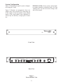
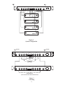
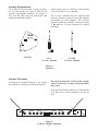
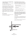
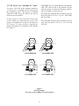
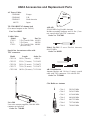
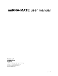
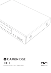
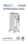
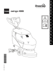
Telex
R
TELEX COMMUNICATIONS, INC. 12000 Portland Ave. South, Burnsville, MN 55337
UAD4
Instruction Sheet
CAT. NO. 301614100
CAT. NO. 301614101
AMPLIFIED UHF
ANTENNA SPLITTER
600-780 MHz
780-900 MHz
PN 804036 Rev A
General Description
It also features a high degree of output isolation;
a necessity in multi-frequency systems to prevent
intermodulation.
The UAD4 Amplified Antenna Splitter makes it
possible to operate four UHF wireless diversity
microphone receivers on four separate frequencies using only two antennas.
The UAD4 Splitter is compatible with Telex
UHF diversity wireless receivers.
SPECIFICATIONS
Frequency Range 301614100 .................................................................................600-780 MHz
301614101.................................................................................780-900 MHz
3rd Order Intercept Output ...........................................................................greater than 18 dbm
Net Gain ............................................................................................................greater than 2 dB
Noise Figure ...........................................................................................................less than 3 dB
Output Isolation...............................................................................................greater than 20 dB
Connectors, Antenna..........................................................................Standard TNC receptacles
Power Requirements................................................................................. 100-240VAC 50/60Hz
Features
The UAD4 is equipped with TNC type connectors. Low loss coaxial cables are also supplied
for splitter to receiver antenna jack connections.
The UAD4 has an internal power supply. Power
out jacks and cables are provided to supply up
to four receivers thus eliminating excess power
supply clutter.
Rack panel mounting “ears” allow the UAD4 to
be mounted in a standard 19 inch equipment
rack. “Knock outs” in the ears allow front connection of antenna cables.
-1-
System Configuration
SPECIAL NOTE: In any system, unused splitter outputs should be terminated with a 50 ohm
“dummy load”. See the accessories listing at the
end of this manual.
Figure 2 illustrates the typical system configuration using the UAD4.
Figure 3 illustrates an arrangement where two
splitters have been cascaded. By connecting one
of the outputs of the first splitter to the antenna
inputs of the second splitter, three additional receivers may be driven by a single pair of antennas.
Telex UAD4
ANTENNA
SPLITTER
POWER
Front View
90-260 VAC 50-60 Hz
OUTPUT A
INPUT A
1
2
3
4
OUTPUT B
POWER OUT
1
2
3
4
1
2
3
4
INPUT B
POWER
15 VDC
Rear View
Figure 1
Front and Rear View
-2-
90-260 VAC 50-60 Hz
OUTPUT A
INPUT A
1
3
2
OUTPUT B
POWER OUT
4
1
3
2
1
4
3
2
4
INPUT B
POWER
15 VDC
RECEIVER 1
RECEIVER 2
RECEIVER 3
RECEIVER 4
Figure 2
System Configuration
ANTENNA
ANTENNA
90-260 VAC 50-60 Hz
OUTPUT A
INPUT A
1
3
2
4
OUTPUT B
POWER OUT
1
2
3
4
1
3
2
4
INPUT B
POWER
15 VDC
TO RECEIVERS
ONLY
TO RECEIVERS
OR SPLITTERS
90-260 VAC 50-60 Hz
OUTPUT A
INPUT A
1
2
3
4
OUTPUT B
POWER OUT
1
2
3
4
1
2
3
4
INPUT B
POWER
15 VDC
TO RECEIVERS ONLY
(DO NOT FEED SPLITTERS FROM SECONDARY UNITS)
Figure 3
Cascading
-3-
Antenna Requirements
The UAD4 may be used with a variety of antennas. For best results, use a pair of ALP-450 directional log periodic antennas. See Figure 4.
The ALP-450 offers the best performance and
broadest bandwidth available.
Telex
Good results may be obtained with optional
CLA or FA-500 1/2 wave antennas.
The 1/4-wave antennas that are supplied with
the Telex wireless systems will provide adequate
performance in some situations. The 1/4-wave
antennas should be oriented as shown in Figure
5. Do not use 1/4-wave antennas for remote
mounting.
R
ALP-450
THIS END TOWARD TRANSMITTER
ALP-450
CLA
1/2 Wave Antenna
FA-500
1/2 Wave Antenna
Figure 4
Antennas
Antenna Placement
Do not rack mount the UAD4 in this configuration. Serious loss of range and performance
may occur.
If antennas are mounted directly to the UAD4,
they should be configured as shown in Figure 5.
Place the UAD4 with antennas in a location that
is in direct view of the transmitters for best results.
90-260 VAC 50-60 Hz
OUTPUT A
INPUT A
1
2
3
4
OUTPUT B
POWER OUT
1
2
3
4
1
2
3
15 VDC
Figure 5
1/2 Wave Antenna Mounting
-4-
4
INPUT B
POWER
Antenna Placement for Optimum Range
and Rack Mounting
Rack Mounted Antenna Connectors
Antenna cable connections may be made to the
front of the rack mounted UAD4 by installing
the adaptor cables supplied. Proceed as follows:
For maximum range and when rack mounting,
the antennas must be remotely located.
·
Remove the plug “knock outs” from the
front panel. See Figure 6.
·
Install the adaptor cables from the back side
of the bracket.
·
Tighten the nut and lockwasher securely.
The ALP-450 comes complete with a variety of
mounting hardware and 10 feet (3 meters) of
low loss coaxial cable. A combination mounting
bracket (Model No. AB-2) with 10 feet of coaxial cable is available for 1/2 wave antennas.
Antennas should be placed in a location with a
clear “signal path” to the transmitter. This “path”
should be as short and free of obstructions as
possible. Obstructions, such as walls ceilings,
and metal objects, will reduce range and performance.
·
Attach the other end of the cables to the inputs of the UAD4. Tighten securely.
Front of rack antenna connectors were designed to allow easier hook up of antenna cables. We do not recommend mounting
antennas directly to the connectors since performance may be degraded.
Rack Mounting
Insert the unit into a 19" rack enclosure and secure with screws (not supplied).
Coax Cable
For best results, it is recommended that cable
losses be kept under 4 dB. (Every 3 dB of signal
loss results in a system operating distance reduction of 25%.
See the accessories section of this manual for
special low loss cable assemblies.
REMOVE PLUG
Figure 6
Antenna Connectors
-5-
CAUTION: Do not attach antennas and splitters
with a DC short circuit to the antenna in jacks
when the power is turned on. Damage could result to the splitter or other devices.
12 Volt Power On "Antenna In" Jacks
To power UAA-500 in-line antenna amplifiers,
12 volt power is available on the center pin of
the antenna in jacks. This power is disabled
when the UAD4 leaves the factory but may be
turned on by the installer.
The following antennas and accessories may be
used with power on: FA-1, CLA-X, ALP-450B,
and UAA-500.
To turn on the 12 volts, first take off the cover
of the splitter by removing the screws. The
jumper is installed on one pin of the header at
the factory. To turn on power, unplug the
jumper and install it on both pins of the header.
See Figure 7.
The following antennas and accessories may be
used with the power off: FA-1, CLA-X, and
ALP-450.
J10
J10
C33 C32
C33 C32
L8
VC3
L8
VC3
J16
C31
J16 POWER ON
J16
C31
J16 POWER OFF
J1
J1
C25 C30 L6
C25 C30 L6
J11
J11
C26
C26
J11 POWER OFF
J11 POWER ON
Figure 7
Moving Jumper
(Be sure to move jumper on both headers)
-6-
UAD4 Accessories and Replacement Parts
AC Power Cables
550024000
550024002
550024013
690513
Telex
Europe
U.K.
North America
Japan
ALP-450
THIS END TOWARD TRANSMITTER
TP-2 50 OHM/TNC dummy load
(For unused outputs on the UAD-4)
Part No. 650095
UAD4 Cables
Model
Type
CXU-2
2 Ft. Coaxial Cable
PC-1
2 Ft. Power
CXU-1
1 Ft. Coaxial Cable
(for rack ears)
ALP-450
450-900 MHz Log Periodic Antenna
Includes mounting hardware and 10 feet (3 meter) coaxial cable with TNC connectors
Order No. 71147000
Part No.
691459
690396
690401
Model FA-500 1/2 wave Flexible Antenna,
680-870 MHz
Order No. 860031
Special low loss antenna cables with
TNC connectors
Model
CXU-10
CXU-25
CXU-50
CXU-75
CXU-100
Length
10 Ft. (3 meter)
25 Ft. (7.6 meter)
50 Ft. (15 meter)
75 Ft. (23 meter)
100 Ft. (30 meter)
R
Order No.
690419
71151-025
71150-075
71151-075
71151-100
AB-2 Combination
Antenna Bracket and 10 foot (3 meter) coaxial
cable with TNC connectors. Use with FA-500
Order No. 71138000
CLA Halfwave Antenna
CLA-1
CLA-2
CLA-3
CLA-4
CLA-5
CLA-6
CLA-8
UAA-500
Low noise antenna amplifier, 500-900 MHz
(antenna not included)
Order No. 7186400
-7-
520-565
565-615
615-660
660-690
690-725
725-760
798-865
MHz
MHz
MHz
MHz
MHz
MHz
MHz
PRINTED IN U.S.A.
Copyright© 2004 by Telex
TELEX COMMUNICATIONS, INC.
All rights reserved
July 2004