1
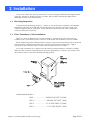
TELEDYNE
HASTINGS
INSTRUMENTS
INSTRUCTION MANUAL
760 PLUS
VACUUM GAUGE
ISO 9001
C E R T I F I E D
Manual Print History
The print history shown below lists the printing dates of all revisions and addenda created for this
manual. The revision level letter increases alphabetically as the manual undergoes subsequent updates.
Addenda, which are released between revisions, contain important change information that the user
should incorporate immediately into the manual. Addenda are numbered sequentially. When a new
revision is created, all addenda associated with the previous revision of the manual are incorporated into
the new revision of the manual. Each new revision includes a revised copy of this print history page.
Revision A (Document Number 147-0497)....................................................................... January 1998
Revision B (Document Number 147-012000)................................................................... January 2000
Revision C (Document Number 147-082002)....................................................................August 2002
Revision D (Document Number 147-092002) ............................................................. September 2002
Revision E (Document Number 147-112003) .............................................................. November 2003
Revision F (Document Number 147-022004) ................................................................... January 2004
Revision G (Document Number 147-082005) ...................................................................August 2005
Revision H (Document Number 147-092005) ............................................................. September 2005
Revision J (Document Number 147-102007) ................................................................... October 2007
Revision K (Document Number 147-082010) ...................................................................August 2010
Visit www.teledyne-hi.com for WEEE disposal guidance.
Hastings Instruments reserves the right to change or modify the design of its equipment without
any obligation to provide notification of change or intent to change.
Manual: 147-082010_HPM-760-Plus-Vacuum-Gauge
Page 2 of 16
Table of Contents
1. GENERAL INFORMATION............................................................................................................................................ 4
1.1.
1.2.
2.
FEATURES .............................................................................................................................................................. 4
SPECIFICATIONS ..................................................................................................................................................... 5
INSTALLATION.......................................................................................................................................................... 6
2.1.
RECEIVING INSPECTION ......................................................................................................................................... 6
2.2.
PIEZO TRANSDUCER (760S) INSTALLATION ........................................................................................................... 6
2.3.
POWER SUPPLY/DISPLAY INSTALLATION ............................................................................................................... 7
2.3.1. Power Supply/Display Cables and Wiring ....................................................................................................... 7
3.
OPERATING INFORMATION.................................................................................................................................. 8
3.1.
GENERAL ............................................................................................................................................................... 8
3.2.
PIEZO TRANSDUCER INPUT POWER ........................................................................................................................ 9
3.3.
PIEZO TRANSDUCER OUTPUT SIGNAL .................................................................................................................... 9
3.4.
POWER SUPPLY/DISPLAY INPUT POWER ................................................................................................................ 9
3.5.
THPS-760 POWER SUPPLY PHYSICAL LAYOUT ..................................................................................................... 9
3.5.1. Front Panel (Refer to page 19, 7.1.1 for physical layout.)............................................................................... 9
3.5.2. Rear Panel...................................................................................................................................................... 10
3.6.
POWER SUPPLY RELAY SET POINT ADJUSTMENT ................................................................................................ 10
3.7.
PRESSURE MEASUREMENTS ................................................................................................................................. 11
4.
CALIBRATION.......................................................................................................................................................... 12
4.1.
4.2.
5.
MAINTENANCE........................................................................................................................................................ 13
5.1.
5.2.
6.
POWER SUPPLY/DISPLAY AUTHORIZED MAINTENANCE ...................................................................................... 13
PIEZO TRANSDUCER AUTHORIZED MAINTENANCE .............................................................................................. 13
WARRANTY .............................................................................................................................................................. 14
6.1.
6.2.
7.
HASTINGS 760 PLUS PIEZO TRANSDUCER ZERO AND SPAN ADJUSTMENT ........................................................... 12
HASTINGS 760S OPTION-5 TRANSDUCER ZERO AND SPAN ADJUSTMENT ............................................................ 12
WARRANTY REPAIR POLICY ................................................................................................................................ 14
NON-WARRANTY REPAIR POLICY ....................................................................................................................... 14
DIAGRAMS AND DRAWINGS ............................................................................................................................... 15
7.1.
7.2.
7.3.
7.4.
FRONT PANEL ...................................................................................................................................................... 15
REAR PANEL ........................................................................................................................................................ 15
MOUNTING ........................................................................................................................................................... 16
PANEL MOUNTING ............................................................................................................................................... 16
Manual: 147-082010_HPM-760-Plus-Vacuum-Gauge
Page 3 of 16
1. General Information
This manual contains technical and general information relating to the installation, operation, and
calibration of the Hastings 760 Plus vacuum gauge which is comprised of a piezo vacuum transducer
(760s) and power supply/display.
The 760s piezoresistive type transducer has one side of its diaphragm evacuated to a low reference
pressure then sealed to produce an absolute pressure signal output. This output signal is linearproportional to the applied pressure and is independent of gas composition.
The power supply/display provides 24 VDC excitation power for the 760s transducer and a four digit
dual setpoint meter relay for monitoring, measurement and control applications.
For best performance, this instrument should be operated with the appropriate Hastings accessory
items. Attempting to use a Hastings product with other manufacturers equipment may result in damage
to all equipment.
1.1. Features
Piezo Vacuum Transducer (760s):
•
Linear voltage or current output
•
Absolute pressure measurement, independent of gas composition
•
Zero and span, adjustable
•
Compact size, 1.5” x 1.5” x 3”
•
0.1 - 1000 Torr range
•
Stand alone operation with 15 - 30 VDC input
•
All wetted materials 316 stainless steel
•
Optional 3-1/2 digit, LCD display
Power Supply/Display:
•
Excitation output for use with Hastings 760S piezo vacuum transducer
•
4 1/2-digit high efficiency red LED display
•
Two control relays, SPDT, 2 A (max) @ 240 VAC (max)
•
Relay set point, set manually from front panel
•
120/240 VAC input power (no hardware settings required)
•
Front panel (SP1, SP2) annunciators (LED’S)
•
1/8 DIN case, panel mounting
Manual: 147-082010_HPM-760-Plus-Vacuum-Gauge
Page 4 of 16
1.2. Specifications
Piezo Vacuum Transducer (760s):
Accuracy ......................................................................................................± 0.25% FS* (760 Torr)
Operating pressure ............................................................................................. 1000 Torr (nominal)
Maximum over pressure..........................................................................................2300 Torr(45 psi)
Operating temperature ............................................................................................................. 0-50°C
Input voltage .....................................................................................................................15-30 VDC
Input power............................................................................................ 15 mA @ 24 VDC (no load)
Output impedance................................................................................................... 1k ohm minimum
Output signal options:
Option-01 ....................................................................................................... 0-1000 Torr @ 0-5 VDC
Option-02 Std. .............................................................................................. 0-1000 Torr @ 0-10 VDC
Option-03......................................................................................................... 0-1000 Torr @ 2-10 mA
Option-04......................................................................................................... 0-1000 Torr @ 4-20 mA
Option-05.......................................................................0-1000 Torr @ 5 or 10 VDC w/digital display
Size........................................................................................................................ 1.5”x 1.5”x 2.875”
Wetted material(s).................................................................................................... 316 stainless steel
Power Supply/Display:
Digital display.......................................................................................... ± 0.05% of reading ± 1 digit
Temperature coefficient ..................................................................................................< 80 ppm/°C
Input power.............................................................................. 120 or 240 volts AC, 50 ma, 50/60 hz
Output power .....................................................................................24 VDC no regulated @ 30 mA
Input signal......................................................................................................... 0-10 VDC (nominal)
Relay(s) .......................................................................................................... 2A @ 240 VAC form C
Size............................................................................................................................ 1.9”x 3.8”x 4.6”
* Accuracy 0.25% FS (calibration based on a 0.15% RDG standard)
Manual: 147-082010_HPM-760-Plus-Vacuum-Gauge
Page 5 of 16
2. Installation
This section contains the necessary instructions to assist in placing the HPM-760 Plus digital vacuum
gauge into operation as quickly and easily as possible. Please read the following thoroughly before
attempting to install or use the instrument.
2.1. Receiving Inspection
Carefully unpack the Hastings product(s). Inspect for any obvious signs of damage to the shipment.
Immediately advise the carrier who delivered the shipment if any damage is suspected. Check each
component shipped with the packing list. Insure that all parts listed are present. Other equipment or
accessories will be listed separately.
2.2. Piezo Transducer (760s) Installation
Figure 2-1 shows the Hastings piezo vacuum transducer. A standard 1/8” NPT male stem and
evacuation port is provided for system connection. VCR and KF stem terminations are also available
When installing transducers with threaded stem, apply an approved vacuum sealant to the stem threads
of the transducer. Hand thread transducer into vacuum system until joint is finger tight. Tighten
transducer module completely using a wrench on the hexagonal portion of the stem.
Do not grip instrument case to tighten; this will result in permanent damage to transducer assembly.
When the 760s is purchased independently of the power supply/display, a connector is provided so that
the transducer can be connected as detailed in the figure below.
TRANSDUCER PINOUT
PIN1.............................SIGNAL OUTPUT (COM)
PIN 2..............................SIGNAL OUTPUT (POS)
PIN 3............................ 15-30 VDC INPUT (COM)
PIN 4.............................. 15-30 VDC INPUT (POS)
Manual: 147-082010_HPM-760-Plus-Vacuum-Gauge
Page 6 of 16
2.3. Power Supply/Display Installation
Cut a panel opening to the following dimensions; 3.62” (92mm) wide, 1.77” (45mm) tall. Insert the
power supply/display through the panel cutout and secure in place using mounting hardware supplied.
2.3.1.
Power Supply/Display Cables and Wiring
Three cables provide all wire connections for the Hastings 760 Plus and are shown below:
760 Plus Interconnect Cable
Fig 2-1
To power supply/display
To Piezo Transducer (760s)
Interconnect cable, 4-cond. # 20 A.W.G., 8-ft length standard
Power Supply/Display Power Cable
To power supply/display
Fig 2-2
AC power cable, 2-cond w/polarized plug., # 18 A.W.G., 8-ft length standard
Manual: 147-082010_HPM-760-Plus-Vacuum-Gauge
Page 7 of 16
3. Operating Information
This section contains information on operating the PIEZO Resistive Transducer in any of its various
configurations. Refer to the appropriate section for information on the mode in use.
3.1. General
The piezoresistive transducer is shown schematically in figure 3-1. Basically the membrane contains an
ion implanted resistive element that is part of a Wheatstone bridge circuit shown in figure 3-2. The
underside of the transducer has been evacuated and sealed to produce a deflection of the membrane the
magnitude of which is a function of the differential pressure (ΔP) across the membrane. The resistance of
the membrane element changes with that ΔP and thus changes the bridge output.
PIEZO RESISTOR
DIOXIDE
DEPLETION
REGION
SILICON
CHIP
VB
Fig 3-1
R+ΔR
R-ΔR
R-ΔR
R+ΔR
VOUT
Fig 3-2
Manual: 147-082010_HPM-760-Plus-Vacuum-Gauge
Page 8 of 16
3.2. Piezo Transducer Input Power
The 760s piezo transducer operates with a DC input from 15 to 30 volts. Use the 4-pin female
connector supplied and makes necessary connections as outlined. See illustration in Section 2 of this
manual.
3.3. Piezo Transducer Output Signal
The 760s piezo transducer provides either a linear DC voltage output with pressure or a linear DC
current output with pressure. The type of output is determined by the instrument option specified. A
brief description of the option, pressure range and output signal is listed below:
OPTION No
PRESSURE RANGE
(Torr)
SIGNAL OUT
(see note
01
0-1000
0-5 VDC
02
0-1000
0-10 VDC
03
0-1000
2-10 mA
04
0-1000
4-20 mA
05
0-1000
0-5 or 10 VDC
w/LCD Digital Display
NOTE: The 760 Plus power supply/ display or the 760s option-05, provide a direct pressure
readout in Torr units.
3.4. Power Supply/Display Input Power
The 760 Plus power supply/display must be connected to a source of AC voltage, either 120 or 240 V,
before attempting to program or setup the unit for operation with the Hastings 760S piezo vacuum
transducer (see Section 2.3 for cable description).
3.5. THPS-760 Power Supply Physical Layout
3.5.1.
Front Panel (Refer to page 19, 7.1.1 for physical layout.)
Digital Display. The THPS-760 has a 4 1/2-digit display that displays continuous readout.
Set Point Adjustment Pots.
Two Set Point Adjustment Pots are accessible on the panel and are used to set the desired set points.
(SP1/SP2) Refer to SET POINT ADJUSTMENTS and figure 1 for specific instructions pertaining to
setting the set points.
THE KNOBS ON THE SET POINT ADJUSTMENT POTS ARE PERMANENTLY
INSTALLED AND CAN NOT BE REMOVED. REMOVING THEM COULD CAUSE
PERMANENT DAMAGE TO THE SET POINT POTS.
Set Point Pushbuttons.
There are two set point pushbuttons (SP1 AND SP2) accessible on the front panel. When depressed,
the setpoint value is displayed on the LED readout
SET POINT LED’s. The two LED indicators (SP1 and SP2) will illuminate when the input pressure
is less than desired (SP1/SP2) set point. The LED’s indicate the corresponding relay is activated
(energized).
Manual: 147-082010_HPM-760-Plus-Vacuum-Gauge
Page 9 of 16
3.5.2.
Rear Panel
Refer to page 19, 7.1.2 for rear view and specific pin outs and connector arrangements.
AC Input Connector J1
Universal input power 110vac to 220 VAC. No hardware settings required.
J3 Input/Output Connector
Sensor Input (pin 9) Input signal from HPM 760S sensor
Sensor Ground (pin 10)
Input ground
Signal output (pin 11)
Signal output return (pin 12)
Auxiliary signal output. (0 to +10vdc)
Auxiliary signal return
24vdc Output (pin 7)
24vdc Return (pin 8)
24vdc Auxiliary output
24vcd Auxiliary return
SP1 relay contacts (pins 1, 2,3) SP1 relay SPDT contacts.
(max)2 amps @ 250vac
SP2 relay contacts (pins 4, 5, 6)) SP2 relay SPDT contacts. (max)2amps @ 250vac
(Either relay will energize when input pressure is less than desired set point).
Grounding Considerations
If the THPS-760 is being used in an area with excessive electromagnetic interference (EMI), the power
supply may need to be grounded. This is accomplished by attaching one end of a grounding wire to the
Thumbscrew located at the rear of the THPS 760. The other end should be connected to the 760 sensor
ground. A shielded cable may be utilized.
3.6. Power Supply Relay Set Point Adjustment
The THPS-760 Power Supply has two separate set points with corresponding LED Indicators and
relay contact outputs. Each Relay has option of either normally open or Normally Closed contacts.
1. Ensure 120vac/220vac is supplied to HPS-760 Power Supply. (No switching necessary.)
2. SP1 setting. Depress SP1 set point switch and hold.
(a)
Turn the SP1 Potentiometer until the desired set point is.
Displayed on digital display.
(b)
Release switch.
3. SP2 setting. Depress SP2 set point switch and hold.
(a)
(b)
Turn the SP2 Set Point Potentiometer until the desired set point is
Displayed on digital display.
Release switch.
4. With both set point push buttons switches released the digital display will indicate input from
HPM-760 sensor. The SP1/SP2 set point relays will energize when the input is less than the
SP1/SP2 set point. Depressing both set point switches at the same time will result in an
erroneous reading, but will not affect the proper operation of the unit.
Manual: 147-082010_HPM-760-Plus-Vacuum-Gauge
Page 10 of 16
Auxiliary Relay Contacts
The THPS-760 Power Supply has SP1 and SP2 relays for various external switching/monitoring
applications. Each relay has a single set of Form “C” contacts. (Choice of normally open or normally
closed contacts). The relays will energize (pick up) when the input is less than the preset set points as
adjusted in the Set Point Adjustment procedures above. The set point LED Indicators (SP1 or SP2) will
illuminate indicating that (SP1 or SP2) relay is energized. The choice of the normally open or normally
closed contacts will depend on the desired switching function of the particular application. Each set of
contacts is capable of switching up to 2 amps (max) @ 250 vac .
3.7. Pressure Measurements
The 760 Plus piezo transducers are shipped from the factory fully calibrated; thus, can provide
immediate and accurate pressure measurements as soon as the installation outlined in Section 2.2 has
been completed. If using a 760 Plus power supply/display, the pressure can be read directly in Torr units.
When not using a 760 Plus power supply/display, the linear output voltage or current depending on
option, must be interpolated to obtain absolute pressure measurements.
Figure 3-3 on the following page of this manual shows a typical signal output vs pressure curve. Note
the excellent linearity over 4-decades of pressure.
The Hastings 760 Plus power supply/display is calibrated at the factory prior to shipment and does not
require adjustment when installed. The user should not attempt to calibrate the Hastings 760 Plus power
supply/display; however, if the display indication is incorrect, calibrate the Hastings piezo transducer by
adjusting the ZERO and SPAN controls as outlined in this manual.
The Hastings transducer can be adjusted by performing the following procedure. If you intend to use
this procedure, you will need a vacuum system capable of achieving base pressures below 1.00E-02 Torr,
and a power supply/display which is calibrated for the option in use.
1000.0
5.0
100.0
0.5
INDICATED
PRESSURE
(TORR)
OUTPUT
VOLTS
10.0
0.05
1.0
0.005
0.1
0.10
0.0005
1.00
10.00
100.00
1000.00
PRESSURE (TORR)
Manual: 147-082010_HPM-760-Plus-Vacuum-Gauge
Page 11 of 16
4.Calibration
4.1. Hastings 760 Plus Piezo Transducer Zero and Span Adjustment
1. Install the transducer and power supply/display then apply operating power. Wait a mini
mum of 15 minutes before proceeding.
2. Evacuate system to a pressure less than 0.010 Torr (1.00E-02 Torr).
3. Adjust transducer zero trimpot (Fig. 2-1) until the power supply/display
indicates 000.0 ±000.1 Torr.
4. Increase system pressure to atmosphere and adjust span trimpot until the power supply/
display indicates the known local atmospheric pressure ±000.1 Torr.
5. Repeat steps 2 through 4 if necessary.
4.2. Hastings 760s Option-5 Transducer Zero and Span Adjustment
1. Install the transducer and apply operating power. Wait a minimum of 15 minutes before
proceeding.
2. Evacuate the system to a pressure less than 0.01 Torr (1.00E-02 Torr).
3. Adjust transducer zero trimpot (Fig. 2-1) until display indicates 000 ± 001 Torr.
4. Increase system pressure to atmosphere and adjust span trimpot (Fig. 2-1) until display
indicates the known local atmospheric pressure ±001 Torr.
5. Repeat steps 2 through 4 if necessary.
Manual: 147-082010_HPM-760-Plus-Vacuum-Gauge
Page 12 of 16
5.Maintenance
5.1. Power Supply/Display Authorized Maintenance
During normal operation and excluding the calibration procedure, Hastings 760 Plus power
supply/display does not require maintenance. In the event a Hastings power supply/display fails or is
otherwise damaged, it should be returned to the manufacturer (factory) for repair or replacement after
first obtaining the necessary returned material authorization (RMA) number.
5.2. Piezo Transducer Authorized Maintenance
During normal operation and excluding the calibration procedure, Hastings piezo vacuum transducers
(760S) do not require maintenance or adjustment. In the event a transducer fails or is otherwise
damaged, it should be returned to the manufacturer (factory) for repair or replacement after first
obtaining the necessary returned material authorization (RMA) number.
Manual: 147-082010_HPM-760-Plus-Vacuum-Gauge
Page 13 of 16
6. WARRANTY
6.1. Warranty Repair Policy
Hastings Instruments warrants this product for a period of one year from the date of shipment to be
free from defects in material and workmanship. This warranty does not apply to defects or failures
resulting from unauthorized modification, misuse or mishandling of the product. This warranty does not
apply to batteries or other expendable parts, or to damage caused by leaking batteries or any similar
occurrence. This warranty does not apply to any instrument which has had a tamper seal removed or
broken.
This warranty is in lieu of all other warranties, expressed or implied, including any implied warranty as
to fitness for a particular use. Hastings Instruments shall not be liable for any indirect or consequential
damages.
Hastings Instruments, will, at its option, repair, replace or refund the selling price of the product if
Hastings Instruments determines, in good faith, that it is defective in materials or workmanship during the
warranty period. Defective instruments should be returned to Hastings Instruments, shipment prepaid,
together with a written statement of the problem and a Return Material Authorization (RMA) number.
Please consult the factory for your RMA number before returning any product for repair. Collect
freight will not be accepted.
6.2. Non-Warranty Repair Policy
Any product returned for a non-warranty repair must be accompanied by a purchase order, RMA form
and a written description of the problem with the instrument. If the repair cost is higher, you will be
contacted for authorization before we proceed with any repairs. If you then choose not to have the
product repaired, a minimum will be charged to cover the processing and inspection. Please consult the
factory for your RMA number before returning any product repair.
TELEDYNE HASTINGS INSTRUMENTS
804 NEWCOMBE AVENUE
HAMPTON, VIRGINIA 23669 U.S.A.
ATTENTION: REPAIR DEPARTMENT
TELEPHONE
TOLL FREE
FAX
E MAIL
INTERNET
(757) 723-6531
1-800-950-2468
(757) 723-3925
[email protected]
http://www.teledyne-hi.com
Repair Forms may be obtained from the “Information Request” section of the Hastings Instruments
web site.
Manual: 147-082010_HPM-760-Plus-Vacuum-Gauge
Page 14 of 16
7. Diagrams and Drawings
7.1. Front Panel
The THPS-760 has a 4 1/2-digit display that displays continuous readout.
7.2. Rear Panel
Decal is to be black ink printed on silver compucal, with adhesive on the back
Manual: 147-082010_HPM-760-Plus-Vacuum-Gauge
Page 15 of 16
7.3. Mounting
Cut out panel as shown in the diagram below.
7.4. Panel Mounting
1) Slide power supply into panel from the top.
2) Attach brackets to the side of the power supply.
3) Tighten screws against panel.
Manual: 147-082010_HPM-760-Plus-Vacuum-Gauge
Page 16 of 16