1
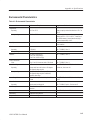
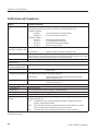
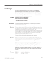
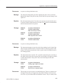
User Manual 1502C Metallic Time-Domain Reflectometer 070-7169-05 This document applies for firmware version 5.04 and above. www.tektronix.com Copyright © Tektronix, Inc. All rights reserved. Tektronix products are covered by U.S. and foreign patents, issued and pending. Information in this publication supercedes that in all previously published material. Specifications and price change privileges reserved. Tektronix, Inc., P.O. Box 500, Beaverton, OR 97077 TEKTRONIX and TEK are registered trademarks of Tektronix, Inc. WARRANTY Tektronix warrants that the products that it manufactures and sells will be free from defects in materials and workmanship for a period of one (1) year from the date of shipment. If a product proves defective during this warranty period, Tektronix, at its option, either will repair the defective product without charge for parts and labor, or will provide a replacement in exchange for the defective product. In order to obtain service under this warranty, Customer must notify Tektronix of the defect before the expiration of the warranty period and make suitable arrangements for the performance of service. Customer shall be responsible for packaging and shipping the defective product to the service center designated by Tektronix, with shipping charges prepaid. Tektronix shall pay for the return of the product to Customer if the shipment is to a location within the country in which the Tektronix service center is located. Customer shall be responsible for paying all shipping charges, duties, taxes, and any other charges for products returned to any other locations. This warranty shall not apply to any defect, failure or damage caused by improper use or improper or inadequate maintenance and care. Tektronix shall not be obligated to furnish service under this warranty a) to repair damage resulting from attempts by personnel other than Tektronix representatives to install, repair or service the product; b) to repair damage resulting from improper use or connection to incompatible equipment; c) to repair any damage or malfunction caused by the use of non-Tektronix supplies; or d) to service a product that has been modified or integrated with other products when the effect of such modification or integration increases the time or difficulty of servicing the product. THIS WARRANTY IS GIVEN BY TEKTRONIX IN LIEU OF ANY OTHER WARRANTIES, EXPRESS OR IMPLIED. TEKTRONIX AND ITS VENDORS DISCLAIM ANY IMPLIED WARRANTIES OF MERCHANTABILITY OR FITNESS FOR A PARTICULAR PURPOSE. TEKTRONIX’ RESPONSIBILITY TO REPAIR OR REPLACE DEFECTIVE PRODUCTS IS THE SOLE AND EXCLUSIVE REMEDY PROVIDED TO THE CUSTOMER FOR BREACH OF THIS WARRANTY. TEKTRONIX AND ITS VENDORS WILL NOT BE LIABLE FOR ANY INDIRECT, SPECIAL, INCIDENTAL, OR CONSEQUENTIAL DAMAGES IRRESPECTIVE OF WHETHER TEKTRONIX OR THE VENDOR HAS ADVANCE NOTICE OF THE POSSIBILITY OF SUCH DAMAGES. Contacting Tektronix Phone 1-800-833-9200* Address Tektronix, Inc. Department or name (if known) 14200 SW Karl Braun Drive P.O. Box 500 Beaverton, OR 97077 USA Web site www.tektronix.com Sales support 1-800-833-9200, select option 1* Service support 1-800-833-9200, select option 2* Technical support Email: [email protected] 1-800-833-9200, select option 3* 1-503-627-2400 6:00 a.m. – 5:00 p.m. Pacific time * This phone number is toll free in North America. After office hours, please leave a voice mail message. Outside North America, contact a Tektronix sales office or distributor; see the Tektronix web site for a list of offices. Table of Contents 1502C MTDR User Manual General Information . . . . . . . . . . . . . . . . . . . . . . . . . . . . . . . . . . . . . . . . vii Installation and Repacking . . . . . . . . . . . . . . . . . . . . . . . . . . . . . . . . . . . . . . . . . . viii Safety Summary . . . . . . . . . . . . . . . . . . . . . . . . . . . . . . . . . . . . . . . . . . . Operating Instructions . . . . . . . . . . . . . . . . . . . . . . . . . . . . . . . . . . . . . . xi 1–1 Overview . . . . . . . . . . . . . . . . . . . . . . . . . . . . . . . . . . . . . . . . . . . . . . . . . . . . . . . Preparing to Use the 1502C . . . . . . . . . . . . . . . . . . . . . . . . . . . . . . . . . . . . . . . . . Display . . . . . . . . . . . . . . . . . . . . . . . . . . . . . . . . . . . . . . . . . . . . . . . . . . . . . . . . . Front-Panel Controls . . . . . . . . . . . . . . . . . . . . . . . . . . . . . . . . . . . . . . . . . . . . . . Menu Selections . . . . . . . . . . . . . . . . . . . . . . . . . . . . . . . . . . . . . . . . . . . . . . . . . . Test Preparations . . . . . . . . . . . . . . . . . . . . . . . . . . . . . . . . . . . . . . . . . . . . . . . . . Cable Test Procedure . . . . . . . . . . . . . . . . . . . . . . . . . . . . . . . . . . . . . . . . . . . . . . Additional Features (Menu Selected) . . . . . . . . . . . . . . . . . . . . . . . . . . . . . . . . . . 1–1 1–5 1–6 1–7 1–8 1–12 1–14 1–29 Operator Tutorial . . . . . . . . . . . . . . . . . . . . . . . . . . . . . . . . . . . . . . . . . . 2–1 What is the Tektronix 1502C? . . . . . . . . . . . . . . . . . . . . . . . . . . . . . . . . . . . . . . . How Does It Do It? . . . . . . . . . . . . . . . . . . . . . . . . . . . . . . . . . . . . . . . . . . . . . . . You, the Operator . . . . . . . . . . . . . . . . . . . . . . . . . . . . . . . . . . . . . . . . . . . . . . . . . Menus and Help . . . . . . . . . . . . . . . . . . . . . . . . . . . . . . . . . . . . . . . . . . . . . . . . . . Getting Started . . . . . . . . . . . . . . . . . . . . . . . . . . . . . . . . . . . . . . . . . . . . . . . . . . . The Waveform Up Close . . . . . . . . . . . . . . . . . . . . . . . . . . . . . . . . . . . . . . . . . . . A Longer Cable . . . . . . . . . . . . . . . . . . . . . . . . . . . . . . . . . . . . . . . . . . . . . . . . . . Ohms-at-Cursor . . . . . . . . . . . . . . . . . . . . . . . . . . . . . . . . . . . . . . . . . . . . . . . . . . Noise . . . . . . . . . . . . . . . . . . . . . . . . . . . . . . . . . . . . . . . . . . . . . . . . . . . . . . . . . . Set Ref (Delta Mode) . . . . . . . . . . . . . . . . . . . . . . . . . . . . . . . . . . . . . . . . . . . . . . VIEW INPUT . . . . . . . . . . . . . . . . . . . . . . . . . . . . . . . . . . . . . . . . . . . . . . . . . . . STORE and VIEW STORE . . . . . . . . . . . . . . . . . . . . . . . . . . . . . . . . . . . . . . . . . VIEW DIFF . . . . . . . . . . . . . . . . . . . . . . . . . . . . . . . . . . . . . . . . . . . . . . . . . . . . . Menu-Accessed Functions . . . . . . . . . . . . . . . . . . . . . . . . . . . . . . . . . . . . . . . . . . TDR Questions and Answers . . . . . . . . . . . . . . . . . . . . . . . . . . . . . . . . . . . . . . . . 2–1 2–1 2–1 2–1 2–2 2–5 2–7 2–8 2–11 2–13 2–17 2–18 2–20 2–21 2–26 Options and Accessories . . . . . . . . . . . . . . . . . . . . . . . . . . . . . . . . . . . . . 3–1 Option 04: YT-1 Chart Recorder . . . . . . . . . . . . . . . . . . . . . . . . . . . . . . . . . . . . . Option 05: Metric Default . . . . . . . . . . . . . . . . . . . . . . . . . . . . . . . . . . . . . . . . . . Option 07: YT-1S Chart Recorder . . . . . . . . . . . . . . . . . . . . . . . . . . . . . . . . . . . . Power Cord Options . . . . . . . . . . . . . . . . . . . . . . . . . . . . . . . . . . . . . . . . . . . . . . . Test data record Option . . . . . . . . . . . . . . . . . . . . . . . . . . . . . . . . . . . . . . . . . . . . Option DE . . . . . . . . . . . . . . . . . . . . . . . . . . . . . . . . . . . . . . . . . . . . . . . . . . . . . . Accessories . . . . . . . . . . . . . . . . . . . . . . . . . . . . . . . . . . . . . . . . . . . . . . . . . . . . . . 3–1 3–1 3–1 3–1 3–2 3–2 3–2 Appendix A: Specifications . . . . . . . . . . . . . . . . . . . . . . . . . . . . . . . . . . . A–1 Electrical Characteristics . . . . . . . . . . . . . . . . . . . . . . . . . . . . . . . . . . . . . . . . . . . Environmental Characteristics . . . . . . . . . . . . . . . . . . . . . . . . . . . . . . . . . . . . . . . Certifications and Compliances . . . . . . . . . . . . . . . . . . . . . . . . . . . . . . . . . . . . . . Physical Characteristics . . . . . . . . . . . . . . . . . . . . . . . . . . . . . . . . . . . . . . . . . . . . A–1 A–3 A–4 A–5 Appendix B: Operator Performance Checks . . . . . . . . . . . . . . . . . . . . Appendix C: Operator Troubleshooting . . . . . . . . . . . . . . . . . . . . . . . . B–1 C–1 Error Messages . . . . . . . . . . . . . . . . . . . . . . . . . . . . . . . . . . . . . . . . . . . . . . . . . . . C–3 i Table of Contents Appendix D: Application Note . . . . . . . . . . . . . . . . . . . . . . . . . . . . . . . . D–1 Pulse Echo Testing of Electrical Transmission Lines Using the Tektronix Time-Domain Reflectometry Slide Rule . . . . . . . . . . . Terms and Symbols . . . . . . . . . . . . . . . . . . . . . . . . . . . . . . . . . . . . . . . . . . . . . . . Relationships . . . . . . . . . . . . . . . . . . . . . . . . . . . . . . . . . . . . . . . . . . . . . . . . . . . . VSWR vs. Percent Reflected Voltage . . . . . . . . . . . . . . . . . . . . . . . . . . . . . . . . . Return Loss (dB) vs. Percent Reflected Voltage . . . . . . . . . . . . . . . . . . . . . . . . . Percent Reflected Voltage vs. Characteristic Line Impedance . . . . . . . . . . . . . . Percent Reflected Voltage vs. Load Resistance . . . . . . . . . . . . . . . . . . . . . . . . . . Characteristic Line Impedance or Load Resistance vs. Reflection Amplitude . . Centimeters vs. Inches or Meters vs. Feet . . . . . . . . . . . . . . . . . . . . . . . . . . . . . . Dielectric Constant vs. Velocity Factor . . . . . . . . . . . . . . . . . . . . . . . . . . . . . . . . Time vs. Short Distances, in Centimeters or Inches (any dielectric) . . . . . . . . . . Time vs. Long Distances, in Meters or Feet (any dielectric) . . . . . . . . . . . . . . . . D–1 D–1 D–2 D–2 D–3 D–4 D–6 D–6 D–7 D–8 D–8 D–9 Glossary Index ii 1502C MTDR User Manual Table of Contents List of Figures Figure 1–1: Rear Panel Voltage Selector, Fuse, AC Receptacle . . . . . Figure 1–2: Display Showing Low Battery Indication . . . . . . . . . . . . . Figure 1–3: 1502C Front-Panel Controls . . . . . . . . . . . . . . . . . . . . . . . Figure 1–4: Display and Indicators . . . . . . . . . . . . . . . . . . . . . . . . . . . . Figure 1–5: Vp Set at .30, Cursor Beyond Reflected Pulse (Set Too Low) . . . . . . . . . . . . . . . . . . . . . . . . . . . . . . . . . . . . . . . . . . . Figure 1–6: Vp Set at .99, Cursor Less Than Reflected Pulse (Set Too High) . . . . . . . . . . . . . . . . . . . . . . . . . . . . . . . . . . . . . . . . . . Figure 1–7: Vp Set at .66, Cursor at Reflected Pulse (Set Correctly) . . . . . . . . . . . . . . . . . . . . . . . . . . . . . . . . . . . . . . . . . . Figure 1–8: 20-ft Cable at 5 ft/div . . . . . . . . . . . . . . . . . . . . . . . . . . . . . Figure 1–9: Short in the Cable . . . . . . . . . . . . . . . . . . . . . . . . . . . . . . . . Figure 1–10: Open in the Cable . . . . . . . . . . . . . . . . . . . . . . . . . . . . . . . Figure 1–11: 455-ft Cable . . . . . . . . . . . . . . . . . . . . . . . . . . . . . . . . . . . . Figure 1–12: 455-ft Cable . . . . . . . . . . . . . . . . . . . . . . . . . . . . . . . . . . . . Figure 1–13: Reflection Adjusted to One Division in Height . . . . . . . Figure 1–14: Return Loss . . . . . . . . . . . . . . . . . . . . . . . . . . . . . . . . . . . . Figure 1–15: Ohms-at-Cursor . . . . . . . . . . . . . . . . . . . . . . . . . . . . . . . . Figure 1–16: Display with VIEW INPUT Turned Off . . . . . . . . . . . . . Figure 1–17: Display of a Stored Waveform . . . . . . . . . . . . . . . . . . . . . Figure 1–18: Display of a Stored Waveform . . . . . . . . . . . . . . . . . . . . . Figure 1–19: Waveform Moved to Top Half of Display . . . . . . . . . . . . Figure 1–20: Current Waveform Centered, Stored Waveform Above . . . . . . . . . . . . . . . . . . . . . . . . . . . . . . . . . . . . . . . . . . . . . . . . . Figure 1–21: Current Waveform Center, Stored Waveform Above, Difference Below . . . . . . . . . . . . . . . . . . . . . . . . . . . . . . . . . . . . . . . . Figure 1–22: Waveform of Three-Foot Lead-in Cable . . . . . . . . . . . . Figure 1–23: Cursor Moved to End of Three-Foot Lead-in Cable . . . Figure 1–24: Cursor Moved to End of Three-Foot Lead-in Cable . . . Figure 1–25: Cursor Moved to 0.00 ft . . . . . . . . . . . . . . . . . . . . . . . . . . Figure 1–26: Incident Pulse at Three Divisions . . . . . . . . . . . . . . . . . . Figure 1–27: Waveform of Short 75 ohm Cable . . . . . . . . . . . . . . . . . . Figure 1–28: Waveform Centered and Adjusted Vertically . . . . . . . . Figure 1–29: Cursor Moved to Desired Position . . . . . . . . . . . . . . . . . Figure 1–30: Waveform Viewed in Normal Operation . . . . . . . . . . . . Figure 1–31: Waveform Showing Intermittent Changes . . . . . . . . . . . 1502C MTDR User Manual 1–2 1–3 1–5 1–6 1–13 1–13 1–13 1–14 1–15 1–15 1–16 1–16 1–17 1–18 1–19 1–20 1–20 1–21 1–22 1–22 1–23 1–24 1–24 1–25 1–25 1–26 1–27 1–27 1–28 1–29 1–30 iii Table of Contents iv Figure 1–32: Waveform Display with No Outgoing Pulses . . . . . . . . . Figure 1–33: A Captured Single Sweep . . . . . . . . . . . . . . . . . . . . . . . . . 1–30 1–32 Figure 2–1: Display Showing 3-ft Cable in Start-Up Conditions . . . . Figure 2–2: Cursor of Rising Edge of Reflected Pulse . . . . . . . . . . . . . Figure 2–3: Waveform with VERT SCALE Increased Showing an Open . . . . . . . . . . . . . . . . . . . . . . . . . . . . . . . . . . . . . . . . . . . . . . . Figure 2–4: Waveform with Short . . . . . . . . . . . . . . . . . . . . . . . . . . . . . Figure 2–5: 3-foot Cable with Cursor at Far Left . . . . . . . . . . . . . . . . Figure 2–6: 3-foot Cable with Cursor at Incident Pulse . . . . . . . . . . . Figure 2–7: 3-foot Cable with Cursor at Incident Pulse, Vertical Scale at 25 dB . . . . . . . . . . . . . . . . . . . . . . . . . . . . . . . . . . . . . . . . . . Figure 2–8: Cursor on End of Longer Cable . . . . . . . . . . . . . . . . . . . . Figure 2–9: Scrolling Down the Cable . . . . . . . . . . . . . . . . . . . . . . . . . . Figure 2–10: Ohms-at-Cursor . . . . . . . . . . . . . . . . . . . . . . . . . . . . . . . . Figure 2–11: Ohms-at-Cursor Near Beginning of Cable . . . . . . . . . . . Figure 2–12: Ohms-at-Cursor Beyond Reflected Pulse . . . . . . . . . . . . Figure 2–13: Ohms-at-Cursor Beyond Reflected Pulse . . . . . . . . . . . . Figure 2–14: Noise on the Waveform . . . . . . . . . . . . . . . . . . . . . . . . . . . Figure 2–15: Noise Reduced . . . . . . . . . . . . . . . . . . . . . . . . . . . . . . . . . . Figure 2–16: Noise Reduced to Minimum . . . . . . . . . . . . . . . . . . . . . . . Figure 2–17: Incident and Reflected Pulses with Cursor at 0.00 ft . . Figure 2–18: Cursor at 3.000 ft . . . . . . . . . . . . . . . . . . . . . . . . . . . . . . . Figure 2–19: New Zero Set at End of Test Cable . . . . . . . . . . . . . . . . . Figure 2–20: Display with 3-ft Cable and NOISE FILTER turned to VERT SET REF . . . . . . . . . . . . . . . . . . . . . . . . . . . . . . . . . . . . . . . . Figure 2–21: VERT SCALE adjusted to Make Pulse Two Divisions High . . . . . . . . . . . . . . . . . . . . . . . . . . . . . . . . . . . . . . . . . . . . . . . . . . Figure 2–22: Display with VIEW INPUT Turned Off . . . . . . . . . . . . . Figure 2–23: Display with VIEW INPUT Turned On . . . . . . . . . . . . . Figure 2–24: Waveform Moved to Upper Portion of the Display . . . . Figure 2–25: Waveform with Cable Shorted . . . . . . . . . . . . . . . . . . . . Figure 2–26: Waveform with Both Current and Stored Waveforms . Figure 2–27: Stored, Current, and Difference Waveforms . . . . . . . . . Figure 2–28: Display with VIEW STORE and VIEW DIFF Disabled Figure 2–29: Short and Open Viewed via Max Hold . . . . . . . . . . . . . . Figure 2–30: Waveform Strobed Down Display in Max Hold . . . . . . Figure 2–31: Display with Pulse Turned Off . . . . . . . . . . . . . . . . . . . . Figure 2–32: Test Cable . . . . . . . . . . . . . . . . . . . . . . . . . . . . . . . . . . . . . . 2–3 2–3 2–4 2–4 2–5 2–6 2–6 2–7 2–8 2–9 2–9 2–10 2–10 2–11 2–12 2–12 2–13 2–14 2–14 2–15 2–16 2–17 2–17 2–18 2–19 2–19 2–20 2–21 2–22 2–22 2–24 2–25 1502C MTDR User Manual Table of Contents Figure 2–33: Captured Single Sweep of Shorted Test Cable . . . . . . . . Figure B–1: Start-up Measurement Display . . . . . . . . . . . . . . . . . . . . . Figure B–2: Measurement Display with 3-foot Cable . . . . . . . . . . . . . Figure B–3: Cursor at End of 3-foot Cable . . . . . . . . . . . . . . . . . . . . . . Figure B–4: Cursor at End of 3-foot Cable, Vp Set to .30 . . . . . . . . . . Figure B–5: Flat-Line Display Out to 50,0000+ Feet . . . . . . . . . . . . . . Figure B–6: Flat-Line Display at –2.000 ft . . . . . . . . . . . . . . . . . . . . . . Figure B–7: Waveform Off the Top of the Display . . . . . . . . . . . . . . . . Figure B–8: Waveform at the Bottom of the Display . . . . . . . . . . . . . . Figure B–9: Waveform with Gain at 5.00 mr/div . . . . . . . . . . . . . . . . . Figure B–10: Top of Pulse on Center Graticule . . . . . . . . . . . . . . . . . . Figure B–11: Rising Edge of Incident Pulse in Left-most Major Division . . . . . . . . . . . . . . . . . . . . . . . . . . . . . . . . . . . . . . . . . . . . . . . . Figure B–12: Waveform Centered, Cursor at 0.000 ft . . . . . . . . . . . . . Figure B–13: Pulse Centered on Display . . . . . . . . . . . . . . . . . . . . . . . . Figure B–14: Cursor on Lowest Major Graticule that Rising Edge crosses . . . . . . . . . . . . . . . . . . . . . . . . . . . . . . . . . . . . . . . . . . . . . . . . . Figure B–15: Cursor on Highest Major Graticule that Rising Edge crosses . . . . . . . . . . . . . . . . . . . . . . . . . . . . . . . . . . . . . . . . . . . . . . . . . Figure B–16: Jitter Apparent on Leading Edge of Incident Pulse . . . Figure B–17: Jitter Captured Using Max Hold . . . . . . . . . . . . . . . . . . Figure D–1: Slide Rule of VSWR vs. Percent Reflected Voltage . . . . Figure D–2: Slide Rule of Return Loss vs. Percent Reflected Voltage . . . . . . . . . . . . . . . . . . . . . . . . . . . . . . . . . . . . . . . . . . . . . . . . Figure D–3: Slide Rule 50 ohm Source . . . . . . . . . . . . . . . . . . . . . . . . . Figure D–4: Slide Rule 75 ohm Source . . . . . . . . . . . . . . . . . . . . . . . . . Figure D–5: Calculating Resistance/Impedance from Waveform Amplitude . . . . . . . . . . . . . . . . . . . . . . . . . . . . . . . . . . . . . . . . . . . . . Figure D–6: English-Metric, Metric-English Conversion Scales . . . . Figure D–7: Dielectric Constant and Velocity Factor, Short Distance . . . . . . . . . . . . . . . . . . . . . . . . . . . . . . . . . . . . . . . . . . . . . . . Figure D–8: Dielectric Constant and Velocity Factor, Long Distance . . . . . . . . . . . . . . . . . . . . . . . . . . . . . . . . . . . . . . . . . . . . . . . 1502C MTDR User Manual 2–25 B–2 B–3 B–3 B–4 B–4 B–5 B–5 B–6 B–6 B–8 B–8 B–9 B–9 B–10 B–10 B–11 B–11 D–2 D–3 D–4 D–5 D–6 D–7 D–8 D–9 v Table of Contents List of Tables vi Table i: Shipping Carton Test Strength . . . . . . . . . . . . . . . . . . . . . . . . ix Table 1–1: Fuse and Voltage Ratings . . . . . . . . . . . . . . . . . . . . . . . . . . Table 1–2: Vp of Various Dielectric Types . . . . . . . . . . . . . . . . . . . . . . 1–2 1–12 Table A–1: Electrical Characteristics . . . . . . . . . . . . . . . . . . . . . . . . . . Table A–2: Environmental Characteristics . . . . . . . . . . . . . . . . . . . . . Table A–3: Physical Characteristics . . . . . . . . . . . . . . . . . . . . . . . . . . . A–1 A–3 A–5 1502C MTDR User Manual General Information Product Description The Tektronix 1502C Metallic Time-Domain Reflectometer (MTDR) is a short-range cable tester capable of finding faults in metal cable. Tests can be made on coaxial, twisted pair, or parallel cable. The 1502C sends an electrical pulse down the cable and detects any reflections made by discontinuities. This is known as time-domain reflectometry. The 1502C is sensitive to impedance changes. Problems in the cable will be detected and displayed as changes in impedance along the cable. These will be displayed as hills and valleys in the reflected pulse. The 1502C is capable of finding shorts, opens, defects in the shield, foreign substances in the cable (e.g., water), kinks, and more. Even though other instruments might show a cable as “good.” the 1502C can show many previously undetected faults. The waveform may be temporarily stored within the 1502C and recalled or may be printed using the optional dot matrix strip chart recorder, which installs into the front-panel Option Port. Battery Pack Options Standards, Documents, and References Used Changes and History Information 1502C MTDR User Manual The 1502C may be operated from an AC power source or an internal lead-acid battery that supply a minimum of five hours operating time (see the Specifications appendix for specifics). Options available for the 1502C are explained in the Options and Accessories chapter of this manual. Terminology used in this manual is in accordance with industry practice. Abbreviations are in accordance with ANSI Y1.1–19722, with exceptions and additions explained in parentheses in the text. Graphic symbology is based on ANSI Y32.2–1975. Logic symbology is based on ANSI Y32.14–1973 and manufacturer’s data books or sheets. A copy of ANSI standards may be obtained from the Institute of Electrical and Electronic Engineers, 345 47th Street, New York, NY 10017. Changes that involve manual corrections and/or additional data will be incorporated into the text and that page will show a revision date on the inside bottom edge. History information is included in any diagrams in gray. vii General Information Installation and Repacking Unpacking and Initial Inspection Before unpacking the 1502C from its shipping container or carton, inspect for signs of external damage. If the carton is damaged, notify the carrier. The shipping carton contains the basic instrument and its standard accessories. Refer to the replaceable parts list in the Service Manual for a complete listing. If the contents of the shipping container are incomplete, if there is mechanical damage or defect, or if the instrument does not meet operational check requirements, contact your local Tektronix Field Office or representative. If the shipping container is damaged, notify the carrier as well as Tektronix. The instrument was inspected both mechanically and electrically before shipment. It should be free if mechanical damage and meet or exceed all electrical specifications. Procedures to check operational performance are in the Performance Checks appendix. These checks should satisfy the requirements for most receiving or incoming inspections. Power Source and Power Requirements The 1502C is intended to be operated from a power source that will not apply more than 250 volts RMS between the supply conductors or between either supply conductor and ground. A protective ground connection, by way of the grounding conductor in the power cord, is essential for safe operation. The AC power connector is a three-way polarized plug with the ground (earth) lead connected directly to the instrument frame to provide electrical shock protection. If the unit is connected to any other power source, the unit frame must be connected to earth ground. Power and voltage requirements are printed on the back panel. The 1502C can be operated from either 115 VAC or 230 VAC nominal line voltage at 45 Hz to 440 Hz, or a battery pack. Further information on the 1502C power requirements can be found in the Safety Summary in this section and in the Operating Instructions chapter. Repacking for Shipment When the 1502C is to be shipped to a Tektronix Service Center for service or repair, attach a tag showing the name and address of the owner, name of the individual at your firm who may be contacted, the complete serial number of the instrument, and a description of the service required. If the original packaging is unfit for use or is not available, repackage the instrument as follows: 1. Obtain a carton of corrugated cardboard having inside dimensions that are at least six inches greater than the equipment dimensions to allow for cushioning. The test strength of the shipping carton should be 275 pounds (102.5 kg). Refer to the following table for test strength requirements: viii 1502C MTDR User Manual General Information Table i: Shipping Carton Test Strength Gross Weight (lb) Carton Test Strength (lb) 0 – 10 200 11 – 30 275 31 – 120 375 121 – 140 500 141 – 160 600 2. Install the front cover on the 1502C and surround the instrument with polyethylene sheeting to protect the finish. 3. Cushion the instrument on all sides with packing material or urethane foam between the carton and the sides of the instrument. 4. Seal with shipping tape or an industrial stapler. If you have any questions, contact your local Tektronix Field Office or representative. 1502C MTDR User Manual ix General Information x 1502C MTDR User Manual General Safety Summary The safety information in this summary is for operating personnel. Specific warnings and cautions will be found throughout the manual where they apply, but might not appear in this summary. For specific service safety information, see the 1502C Service Manual. Safety Terms and Symbols Terms in this manual: WARNING. Warning statements identify conditions or practices that could result in injury or loss of life. CAUTION. Caution statements identify conditions or practices that could result in damage to this product or other property. Terms on the Product: DANGER indicates an injury hazard immediately accessible as you read the marking. WARNING indicates an injury hazard not immediately accessible as you read the marking. CAUTION indicates a hazard to property including the product. Symbols in the Manual: WARNING or CAUTION Information Symbols on the Product: DANGER High Voltage 1502C MTDR User Manual Protective Ground (Earth) Terminal ATTENTION Refer to Manual Double Insulated xi General Safety Summary Power Source This product is intended to operate from a power source that will not apply more than 250 volts RMS between the supply conductors or between the supply conductor and ground. A protective ground connection, by way of the grounding conductor in the power cord, is essential for safe operation. Grounding the Product This product is grounded through the grounding conductor of the power cord. To avoid electrical shock, plug the power cord into a properly wired receptacle before connecting to the product input or output terminals. A protective ground connection by way of the grounding conductor in the power cord is essential for safe operation. Danger Arising from Loss of Ground Upon loss of the protective-ground connection, all accessible conductive parts (including knobs and controls that appear to be insulating) can render an electric shock. Use the Proper Power Cord Use only the power cord and connector specified for this product. Do not use this instrument without a rated AC line cord. The standard power cord (161-0288-00) is rated for outdoor use. All other optional power cords are rated for indoor use only. Use only a power cord that is in good condition. Refer cord and connector changes to qualified service personnel. Use the Proper Fuse To avoid fire hazard, use only a fuse of the correct type. Refer fuse replacement to qualified service personnel. Do Not Operate in Explosive Atmosphere Do Not Remove Covers or Panels Connecting Cables to the Front-Panel BNC Disposal of Batteries xii To avoid explosion, do not operate this product in an explosive atmosphere unless it has been specifically certified for such operation. To avoid personal injury, do not remove the product covers or panels. Do not operate the product without the covers and panels properly installed. To avoid possible damage to the front-end circuitry, connection of a cable that is, or can be, driven by active circuitry should be avoided if the voltage could exceed 400 V. This instrument contains a lead-acid battery. Some states and/or local jurisdictions might require special disposition/recycling of this type of material in accordance with Hazardous Waste guidelines. Check your local and state regulations prior to disposing of an old battery. 1502C MTDR User Manual General Safety Summary Tektronix Factory Service will accept 1502C batteries for recycling. If you choose to return the battery to us for recycling, the battery cases must be intact, the battery should be packed with the battery terminals insulated against possible short-circuits, and should be packed in shock-absorbant material. Tektronix, Inc. Attn: Service Department P.O. Box 500 Beaverton, Oregon 97077 U.S.A. For additional information, phone:1–800–TEK–WIDE 1502C MTDR User Manual xiii General Safety Summary xiv 1502C MTDR User Manual Operating Instructions Overview Handling The 1502C front panel is protected by a watertight cover, in which the standard accessories are stored. Secure the front cover by snapping the side latches outward. If the instrument is inadvertently left on, installing the front cover will turn off the POWER switch automatically. The carrying handle rotates 325° and serves as a stand when positioned beneath the instrument. Inside the case, at the back of the instrument, is a moisture-absorbing canister containing silica gel. In extremely wet environments, it might be be necessary to periodically remove and dry the canister. This procedure is explained in the 1502C Service Manual. The 1502C can be stored in temperatures ranging from –62° C to +85° C if a battery is not installed. If a battery is installed and the storage temperature is below –35° C or above +65° C, the battery pack should be removed and stored separately (see 1502C Service Manual for instructions on removing the battery). Battery storage temperature should be between –35° C to +65° C. Powering the 1502C In the field, the 1502C can be powered using the internal battery. See Figure 1–1. For AC operation, check the rear panel for proper voltage setting. The voltage selector can be seen through the window of the protective cap. If the setting differs from the voltage available, it can be easily changed. Simply remove the protective cap and select the proper voltage using a screwdriver. The 1502C is intended to be operated from a power source that will not apply more than 250 V RMS between the supply conductors or between either supply conductor and ground. A protective ground connection by way of the grounding conductor in the power cord is essential for safe operation. The AC power connector is a three-way polarized plug with the ground (earth) lead connected to the instrument frame to provide electrical shock protection. If the unit is connected to any other power source, the unit frame must be connected to an earth ground. See Safety and Installation section. CAUTION. If you change the voltage selector, you must change the line fuse to the appropriate value as listed near the fuse holder and in the table below. 1502C MTDR User Manual 1–1 Operating Instructions REMOVE CAP TO SELECT VOLTAGE REMOVE CAP TO REPLACE FUSE Voltage Selector Line Fuse AC Power Cord Receptacle Figure 1–1: Rear Panel Voltage Selector, Fuse, AC Receptacle Table 1–1: Fuse and Voltage Ratings Fuse Rating Voltage Rating 250 V Nominal Range 0.3 AT 115 VAC (90 – 132 VAC) 0.15 AT 230 VAC (180 – 250 VAC) Care of the Battery Pack CAUTION. Read these instructions concerning the care of the battery pack. They contain instructions that reflect on your safety and the performance of the instrument. The 1502C can be powered by a rechargeable lead-gel battery pack that is accessible only by removing the case from the instrument. When AC power is applied, the battery pack is charged at a rate that is dependent on the battery charge state. The battery pack will operate the 1502C for a minimum of eight continuous hours (including making 30 chart recordings) if the LCD backlight is turned off. 1–2 1502C MTDR User Manual Operating Instructions Battery Charging The battery pack will charge fully in 16 hours when the instrument is connected, via the power cord, to an AC power source with the instrument turned off. The instrument may be turned on and operated while the batteries are charging, but this will increase the charging time. For longest battery life, a full charge is preferred over a partial charge. For maximum capacity, the batteries should be charged within a temperature range of +20° C to +25° C. However, the batteries can be charged within a temperature range of 0° C to +40° C and operated in temperatures ranging from –10° C to +55° C. CAUTION. Do not charge battery pack below 0° C or above +40° C. Do not discharge battery pack below –10° C or above +55° C. If removing the battery pack during or after exposure to these extreme conditions, turn the instrument off and remove the AC power cord. The battery pack should be stored within a temperature range of –35° C to +65° C. However, the self-discharge rate will increase as the temperature increases. If the instrument is stored with the battery pack installed, the battery pack should be charged every 90 days. A fully charged battery pack will lose about 12% of its capacity in three to four months if stored between +20° C and +25° C. Low Battery If the battery is low, it will be indicated on the LCD (bat/low). If this is the case, protective circuitry will shut down the 1502C within minutes. Either switch to AC power or work very fast. If the instrument is equipped with a chart recorder, using the recorder will further reduce the battery level, or the added load might shut down the instrument. bat/low 0.00 ft O N Low Battery Indicator O F F O F F O F F 1 avg 500 mr 500 ft Figure 1–2: Display Showing Low Battery Indication 1502C MTDR User Manual 1–3 Operating Instructions Protection circuits in the charger prevent deep discharge of the batteries during instrument operation. The circuits automatically shut down the instrument whenever battery voltage falls below approximately 10 V. If shutdown occurs, the batteries should be fully recharged before further use. NOTE. Turn the POWER switch off after instrument shutdown to prevent continued discharge of the batteries. Low Temperature Operation When the instrument is stored at temperatures below –10° C, voids might develop in the liquid crystal display (LCD). These voids should disappear if the instrument is placed in an ambient temperature ≥ +5° C for 24 hours. When operating the 1502C in an environment below +10° C, a heater will activate. The element is built into the LCD module and will heat the display to permit normal operation. Depending on the surrounding temperature, it might take up to 15 minutes to completely warm the crystals in the LCD. Once warmed, the display will operate normally. 1–4 1502C MTDR User Manual Operating Instructions Preparing to Use the 1502C Check the power requirements, remove the front cover, and you are ready to test cables. The following pages explain the front-panel controls. 7 8 9 Tektronix 10 ac MENU VIEW INPUT 11 VIEW STORE 12 VIEW DIFF 13 METALLIC TDR 1502C CABLE TESTER POSITION 0.00 ft O N POSITION O F F O F F STORE O F F 1 avg 500 mr DO NOT APPLY EXT VOLTAGE NOISE FILTER VERT SCALE 0.2 ft DIST/DIV .4 .3 HORZ VERT 1 SET REF 2 3 4 .5 Vp .04 .6 .03 .7 .02 .8 .01 .9 .00 5 .05 .06 .07 .08 .09 POWER (PULL ON) 6 Figure 1–3: 1502C Front-Panel Controls CAUTION. Do not connect live circuits to the CABLE connector. Voltages exceeding 5 volts can damage the pulser or sampler circuits. Bleed the test cable of any residual static charge before attaching it to the instrument. To bleed the cable, connect the standard 50 W terminator and standard female-to-female BNC connector together, then temporarily attach both to the cable. Remove the connectors before attaching the cable to the instrument. When testing receiving antenna cables, avoid close proximity to transmitters. Voltages may appear on the cable if a nearby transmitter is in use, resulting in damage to the instrument. Before testing, be sure that there are no RF voltages present, or disconnect the cable at both ends. 1502C MTDR User Manual 1–5 Operating Instructions Display Power Type Waveform Front-Panel to Cursor Distance Window Cursor ac View Input Indicator O N View Store Indicator O F F View Difference Indicator O F F Store Indicator O F F 0.00 ft Grid 1 avg Selected Noise Filter 500 mr Selected Vertical Scale 0.2 ft Selected Distance per Division Figure 1–4: Display and Indicators 1–6 1502C MTDR User Manual Operating Instructions Front-Panel Controls 1. CABLE: A female BNC connector for attaching a cable to the 1502C for testing. 2. NOISE FILTER: If the displayed waveform is noisy, the apparent noise can be reduced by using noise averaging. Averaging settings are between 1 and 128. The time for averaging is directly proportional to the averaging setting chosen. A setting of 128 might take the instrument up to 35 seconds to acquire and display a waveform. The first two positions on the NOISE FILTER control are used for setting the vertical and horizontal reference points. The selected value or function is displayed above the control on the LCD. NOISE FILTER HORZ SET REF VERT VERT SCALE 3. VERT SCALE: This control sets the vertical sensitivity, displayed in mr per division, or the vertical gain, displayed in dB. Although the instrument defaults to millirho, you may choose the preferred mode from the Setup Menu. The selected value is displayed above the control on the LCD. DIST/DIV 4. DIST/DIV: Determines the number of feet (or meters) per division across the display. The minimum setting is 0.1 ft/div (0.025 meters) and the maximum setting is 200 ft/div (50 meters). The selected value is displayed above the control on the LCD. A standard instrument defaults to ft/div. A metric instrument (Option 05) defaults to m/div, but either may be changed temporarily from the menu. The default can be changed by changing an internal jumper (see 1502C Service Manual and always refer such changes to qualified service personnel). Vp .4 .3 .5 .03 .6 .04 .05 .7 .02 .9 .8 .01 .00 .06 .07 .08 .09 POWER (PULL ON) n POSITION o 5. Vp: The two Velocity of Propagation controls are set according to the propagation velocity factor of the cable being tested. For example, solid polyethylene commonly has a Vp of 0.66. Solid polytetraflourethylene (Teflon ) is approximately 0.70. Air is 0.99. The controls are decaded: the left control is the first digit and the right control is the second digit. For example, with a Vp of 0.30, the first knob would be set to .3 and the second knob to .00. 6. POWER: Pull for power ON and push in for power OFF. When the front cover is installed, this switch is automatically pushed OFF. 7. n o POSITION: This is a continuously rotating control that positions the displayed waveform vertically, up or down the LCD. n o 1502C MTDR User Manual n o 8. POSITION POSITION: This is a continuously rotating control that moves a vertical cursor completely across the LCD graticule. In addition, the waveform is also moved when the cursor reaches the extreme right or left side of the display. A readout (seven digits maximum) is displayed in the 1–7 Operating Instructions upper right corner of the LCD, showing the distance from the front panel BNC to the current cursor location. MENU VIEW INPUT 9. MENU: This pushbutton provides access to the menus and selects items chosen from the menus. 10. VIEW INPUT: When pushed momentarily, this button toggles the display of the waveform acquired at the CABLE connector. This function is useful to stop displaying a current waveform to avoid confusion when looking at a stored waveform. This function defaults to ON when the instrument is powered up. VIEW STORE 11. VIEW STORE: When pushed momentarily, this button toggles the display of the stored waveform. VIEW DIFF 12. VIEW DIFF: When pushed momentarily, this button toggles the display of the current waveform minus the stored waveform and shows the difference between them. STORE 13. STORE: When pushed momentarily, the waveform currently displayed will be stored in the instrument memory. If a waveform is already stored, pushing this button will erase it. The settings of the stored waveform are available from the first level menu under View Stored Waveform Settings. Menu Selections There are several layers of menu, as explained below. Main Menu The Main Menu is entered by pushing the MENU button on the front panel. 1. Return to Normal Operations puts the instrument into normal operation mode. 2. Help with Instrument Controls explains the operation of each control. When a control or switch is adjusted or pushed, a brief explanation appears on the LCD. 3. Cable Information has these choices: a. Help with Cables gives a brief explanation of cable parameters. b. Velocity of Propagation Values displays a table of common dielectrics and their Vp values. These are nominal values. The manufacturer’s listed specifications should be used whenever possible. c. Impedance Values displays impedances of common cables. In some cases, these values have been rounded off. Manufacturer’s specifications should be checked for precise values. 1–8 1502C MTDR User Manual Operating Instructions d. Finding Unknown Vp Values describes a procedure for finding an unknown Vp. 4. Setup Menu controls the manner in which the instrument obtains and displays its test results. a. Acquisition Control Menu has these choices: i. Max Hold Is: On/Off. Turn Max Hold on by pushing MENU then STORE. In this mode, waveforms are accumulated on the display. Max Hold can be deactivated by pushing STORE or the mode exited by using the Setup Menu. ii. Pulse Is: On/Off. Turns the pulse generator off so the 1502C does not send out pulses. iii. Single Sweep Is: On/Off. This function is much like a still camera; it will acquire one waveform and hold it. b. Ohms-at-Cursor is: On/Off. When activated, the impedance at thee point of the cursor is displayed beneath the distance window on the display. c. Vertical Scale Is: dB/mr. This offers you a choice as to how the vertical gain of the instrument is displayed. You may choose decibels or millirho. When powered down, the instrument will default to millirho when powered back up. d. Distance/Div Is: ft/m. Offers you a choice of how the horizontal scale is displayed. You may choose from feet per division or meters per division. When powered up, the instrument will default to feet unless the internal jumper has been moved to the meters position. Instructions on changing this default are contained in the 1502C Service Manual. e. Light Is: On/Off. This control turns the electroluminescent backlight behind the LCD on or off. 5. Diagnostics Menu lists an extensive selection of diagnostics to test the operation of the instrument. NOTE. The Diagnostics Menu is intended for instrument repair and calibration. Proper instrument setup is important for correct diagnostics results. Refer to the 1502C Service Manual for more information on diagnostics. a. Service Diagnostics Menu has these choices: i. 1502C MTDR User Manual Sampling Efficiency Diagnostic displays a continuous efficiency diagnostic of the sampling circuits. 1–9 Operating Instructions ii. Noise Diagnostic measures the internal RMS noise levels of the instrument. iii. Offset/Gain Diagnostic reports out-of-tolerance steps in the programmable gain stage. This can help a service technician to quickly isolate the cause of waveform distortion problems. iv. RAM/ROM Diagnostics Menu performs tests on the RAM (Random Access Memory) and the ROM (Read Only Memory). v. Timebase Is: Normal - Auto Correction / Diagnostic - No Correction. When in Normal - Auto Correction, the instrument compensates for variations in temperature and voltage. This condition might not be desirable while calibrating the instrument. While in Diagnostic - No Correction, the circuits will not correct for these variations. b. Front Panel Diagnostics aids in testing the front panel. c. LCD Diagnostics Menu has these choices: i. LCD Alignment Diagnostic generates a dot pattern of every other pixel on the LCD. These pixels can be alternated to test the LCD. ii. Response Time Diagnostic generates alternate squares of dark and light, reversing their order. This tests the response time of the LCD and can give an indication of the effectiveness of the LCD heater in a cold environment. iii. LCD Drive Test Diagnostic generates a moving vertical bar pattern across the LCD. iv. Contrast Adjust allows you to adjust the contrast of the LCD. It generates an alternating four-pixel pattern. The nominal contrast is set internally. When in Contrast Adjust mode, VERT SCALE is used as the contrast adjustment control. This value ranges from 0 to 255 units and is used by the processor to evaluate and correct circuit variations caused by temperature changes in the environment. When the diagnostic menu is exited, the LCD contrast returns to that set by internal adjust. d. Chart Diagnostics Menu offers various tests for the optional chart recorder. i. LCD Chart allows adjusting the number of dots per segment and the number of prints (strikes) per segment. ii. Head Alignment Chart generates a pattern to allow mechanical alignment of the optional chart recorder. 1–10 1502C MTDR User Manual Operating Instructions 6. View Stored Waveform Settings displays the instrument settings for the stored waveform. 7. Option Port Menu contains three items. Two items allow configuration of the option port for communicating with devices other than the optional chart recorder and one item test the option port. a. Option Port Diagnostic creates a repeating pattern of signals at the option port to allow service technicians to verify that all signals are present and working correctly. b. Set Option Port Timing allows adjustment of the data rate used to communicate with external devices. The timing rate between bytes can be set from about 0.05 to 12.8 milliseconds. c. Option Port Debugging Is Off/On. Off is quiet, On is verbose. This chooses how detailed the error message reporting will be when communicating with an external device. It is possible to connect the instrument to a computer through a parallel interface with a unique software driver. Because different computers vary widely in processing speed, the instrument must be able to adapt to differing data rates while communicating with those computers. With user-developed software drivers, the ability to obtain detailed error messages during the development can be very useful. For more information, contact your Tektronix Customer Service representatives. They have information describing the option port hardware and software protocol and custom development methods available. The SP-232, a serial interface product, also allows for connection of the 1502C to other instrumentation, including computers, via the option port. SP-232 is an RS-232C-compatible interface. For more information, contact your Tektronix Customer Service Representative. They can provide you with additional details on the hardware and software protocol. 8. Display Contrast (Software Version 5.02 and above) a. Press the MENU button firmly once. If the display is very light or very dark, you might not be able to see a change in the contrast. b. Turn the VERTICAL SCALE knob slowly clockwise to darken the display or counterclockwise to lighten the display. If you turn the knob far enough, the contrast will wrap from the darkest to lightest value. c. When the screen is clearly readable, press the MENU button again to return to normal measurement operation. The new contrast value will remain in effect until the instrument is turned off. 1502C MTDR User Manual 1–11 Operating Instructions Test Preparations The Importance of Vp (Velocity of Propagation) Vp is the speed of a signal down the cable given as a percentage of the speed of light in free space. It is sometimes expressed as a whole number (e.g., 66) or a percentage (e.g., 66%). On the 1502C, it is the percentage expressed as a decimal number (e.g., 66% = .66). If you do not know the velocity of propagation, you can get a general idea from the following table, or use the Help with Cables section of the Cable Information menu. You can also find the Vp with the procedure that follows using a cable sample. NOTE. If you do not know the Vp of your cable, it will not prevent you from finding a fault in your cable. However, if the Vp is set wrong, the distance readings will be affected. All Vp settings should be set for the cable under test, not the supplied jumper cable. Table 1–2: Vp of Various Dielectric Types Finding an Unknown Vp Dielectric Probable Vp Jelly Filled .64 Polyethylene (PIC, PE, or SPE) .66 PTFE (Teflon R) or TFE .70 Pulp Insulation .72 Foam or Cellular PE (FPE) .78 Semi-solid PE (SSPE) .84 Air (helical spacers) .98 1. Obtain a known length of cable of the exact type you wish to test. Attach the cable to the CABLE connector on the front panel. 2. Pull POWER on. 3. Turn the DIST/DIV to an appropriate setting (e.g., if trying to find the Vp of a three-foot cable, turn the DIST/DIV to 1 ft/div). n o 4. Turn the POSITION control until the distance reading is the same as the known length of this cable. 5. Turn the Vp controls until the cursor is resting on the rising portion of the reflected pulse. The Vp controls of the instrument are now set to the Vp of the cable. 1–12 1502C MTDR User Manual Operating Instructions The following three illustrations show settings too low, too high, and correct for a sample three-foot cable. ac 3.000 ft O N O F F O F F O F F Figure 1–5: Vp Set at .30, Cursor Beyond Reflected Pulse (Set Too Low) ac 3.000 ft O N O F F O F F O F F Figure 1–6: Vp Set at .99, Cursor Less Than Reflected Pulse (Set Too High) ac 3.000 ft O N O F F O F F O F F Figure 1–7: Vp Set at .66, Cursor at Reflected Pulse (Set Correctly) 1502C MTDR User Manual 1–13 Operating Instructions Cable Test Procedure Distance to the Fault Be sure to read the previous paragraphs on Vp. 1. Set the 1502C controls: POWER CABLE NOISE FILTER VERT SCALE DIST/DIV Vp On Cable to BNC 1 avg 500 mr (see below) (per cable) 2. If you know approximately how long the cable is, set the DIST/DIV appropriately (e.g., 20-ft cable would occupy four divisions on the LCD if 5 ft/div was used). The entire cable should be displayed. ac 0.000 ft O N O F F O F F O F F Figure 1–8: 20-ft Cable at 5 ft/div If the cable length is unknown, set DIST/DIV to 200 ft/div and continue to decrease the setting until the reflected pulse is visible. Depending on the cable length and the amount of pulse energy absorbed by the cable, it might be necessary to increase the VERT SCALE to provide more gain to see the reflected pulse. 1–14 1502C MTDR User Manual Operating Instructions ac 20.000 ft O N O F F Short O F F O F F Figure 1–9: Short in the Cable When the entire cable is displayed, you can tell if there is an open or a short. Essentially, a large downward pulse indicates a short (see Figure 1–9), while a large upward pulse indicates an open (see Figure 1–10). Less catastrophic faults can be seen as smaller reflections. Bends and kinks, frays, water, and interweaving all have distinctive signatures. ac 20.000 ft O N O F F Open O F F O F F Figure 1–10: Open in the Cable n o POSITION 3. To find the distance to the fault or end of the cable, turn the control until the cursor rests on the leading edge of the rising or falling reflected pulse (see Figure 1–10). Read the distance in the distance window in the upper right corner of the display. A more thorough inspection might be required. This example uses a longer cable: 4. When inspecting a 452-foot cable, a setting of 50 ft/div allows a relatively fast inspection. If needed, turn VERT SCALE to increase the gain. The higher the gain, the smaller the faults that can be detected. If noise increases, increase the NOISE FILTER setting. 1502C MTDR User Manual 1–15 Operating Instructions ac 452.000 ft O N Open O F F O F F O F F Figure 1–11: 455-ft Cable n o 5. Change DIST/DIV to 20 ft/div. The entire cable can now be inspected in detail on the LCD. Turn the POSITION control so the cursor travels to the far right side of the LCD. Keep turning and the cable will be “dragged” across the display. ac 452.000 ft O N O F F Short O F F O F F Figure 1–12: 455-ft Cable A “rise” or “fall” is a signature of an impedance mismatch (fault). A dramatic rise in the pulse indicates and open. A dramatic lowering of the pulse indicates a short. Variations, such as inductive and capacitive effects on the cable, will appear as bumps and dips in the waveform. Capacitive faults appear as a lowering of the pulse (e.g., water in the cable). Inductive faults appear as a rising of the pulse (e.g., fray). Whenever an abnormality is found, set the cursor at the beginning of the fault and read the distance to the fault on the distance window of the LCD. 1–16 1502C MTDR User Manual Operating Instructions Reflection Coefficient Measurements The reflection coefficient is a measure of the impedance change at a point in the cable. It is the ratio of the signal reflected back from a point, divided by the signal going into that point. It is designated by the Greek letter r and is written in this manual as rho. The 1502C measures the reflection coefficient in millirho (thousandths of a rho). To measure a reflection, adjust VERT SCALE to make the reflection one division high. Read the reflection coefficient directly off the display above the VERT SCALE control. For reflections that are greater than 500 mr/div, adjust VERT SCALE for a reflection that is two divisions high and multiply the VERT SCALE reading by two. ac 0.000 ft O N O F F O F F O F F Figure 1–13: Reflection Adjusted to One Division in Height In an ideal transmission system with no changes in impedance, there will be no reflections, so rho is equal to zero. A good cable that is terminated in its characteristic impedance is close to ideal and will appear as a flat line on the 1502C display. Small impedance changes, like those from a connector, might have reflections from 10 to 100 mr. If rho is positive, it indicates an impedance higher than that of the cable before the reflection. It will show as an upward shift or bump on the waveform. If rho is negative, it indicates an impedance lower than that of the cable prior to the reflection. It will show as a downward shift or dip on the waveform. If the cable has an open or short, all the energy sent out by the 1502C will be reflected. This is a reflection coefficient of rho = 1, or +1000 mr for the open and –1000 mr for the short. Long cables have enough loss to affect the size of reflections. In the 1502C, this loss will usually be apparent as an upward ramping of the waveform along the length of the cable. In some cases, the reflection coefficient measurement can be corrected for this loss. This correction can be made using a procedure very 1502C MTDR User Manual 1–17 Operating Instructions similar to the Vertical Compensation for Higher Impedance Cable procedure (see the VERT SET REF section). Return Loss Measurements Return loss is another was of measuring impedance changes in a cable. Mathematically, return loss is related to rho by the formula: Return Loss (in dB) = –20 * log (base ten) of Absolute Value of Rho (Vref/Vinc) The 1502C can be made to display in dB instead of mr/div through the menu: 1. Press MENU. 2. Select Setup Menu. 3. Press MENU again. 4. Select Vertical Scale is: Millirho. 5. Press MENU again. This should change is to Vertical Scale is: Decibels. 6. Press MENU twice to return to normal operation. To measure return loss with the 1502C, adjust the height of the reflected pulse to be two divisions high and read the dB return loss directly off the LCD. The incident pulse is set to be two divisions high at zero dB automatically when the instrument is turned on. ac 0.000 ft O N O F F O F F O F F Figure 1–14: Return Loss A large return loss means that most of the pulse energy was lost instead of being returned as a reflection. The lost energy might have been sent down the cable or absorbed by a terminator or load on the cable. A terminator matched to the cable would absorb most of the pulse, so its return loss would be large. An open or short would reflect all the energy, so its return loss would be zero. 1–18 1502C MTDR User Manual Operating Instructions Ohms-at-Cursor The 1502C can compute and display what impedance mismatch would cause a reflection as high (or low) as the point at the cursor. This measurement is useful for evaluating the first impedance mismatch (first reflection) or small impedance changes along the cable (e.g., connectors, splices). This function can be selected in the Setup Menu. Once it is enabled, the impedance value will be displayed under the distance in the distance window. ac 2.800 ft 50 W Ohms-at-Cursor Readout O N O F F O F F O F F Figure 1–15: Ohms-at-Cursor The accuracy of the difference measurement in impedance between two points near each other is much better than the absolute accuracy of any single point measurement. For example, a cable might vary from 51.3 W to 58.4 W across a connector, the 7.1 W difference is accurate to about 2%. The 51.3 W measurement by itself is only specified to be accurate to 10%. The series resistance of the cable to the point at the cursor affects the accuracy of the impedance measurement directly. In a cable with no large impedance changes, the series resistance is added to the reading. For example, the near end of a long 50 W coaxial cable might read 51.5 W, but increase to 57.5 W several hundred feet along the cable. The 6 W difference is due to the series resistance of the cable, not to a change in the actual impedance of the cable. Another limitation to the ohms-at-cursor function is that energy is lost going both directions through a fault. This will cause readings of points farther down the cable to be less accurate than points nearer to the instrument. In general, it is not wise to try to make absolute measurements past faults because the larger the fault, the less accurate those measurements will be. Although they do not appear as faults, resistive pads (often used to match cable impedances) also affect measurements this way. 1502C MTDR User Manual 1–19 Operating Instructions Using VIEW INPUT When pushed, the VIEW INPUT button displays the input at the front panel CABLE connector. When VIEW INPUT is turned off and no other buttons are pushed, the display will not have a waveform on it (see Figure 1–16). The default condition when the instrument is powered up is to have VIEW INPUT on. ac 0.000 ft O F F O F F O F F O F F Figure 1–16: Display with VIEW INPUT Turned Off How to Store the Waveform When pushed, the STORE button puts the current waveform being displayed into memory. If already stored, pushing STORE again will erase the stored waveform. The front panel control settings and the menu-accessed settings are also stored. They are accessed under View Stored Waveform Settings in the first level of the menu. ac 3.000 ft O N O F F O F F O N Figure 1–17: Display of a Stored Waveform 1–20 1502C MTDR User Manual Operating Instructions Using VIEW STORE The VIEW STORE button, when pushed on, displays the waveform stored in the memory as a dotted line. If there is no waveform in memory, a message appears on the LCD informing you of this. ac 3.000 ft O F F O N O F F O N Figure 1–18: Display of a Stored Waveform Using VIEW DIFF When pushed on, the VIEW DIFF button displays the difference between the current waveform and the stored waveform as a dotted line. If no waveform has been stored, a message will appear. The difference waveform is made by subtracting each point in the stored waveform from each point in the current waveform. NOTE. If the two waveforms are identical (e.g., if STORE is pushed and VIEW DIFF is immediately pushed) the difference would be zero. Therefore you would see the difference waveform as a straight line. The VIEW DIFF waveform will move up and down with the current input as you move the n POSITION control. Any of the waveforms may be turned on or off o independently. You might want to turn off some waveforms if the display becomes too busy or confusing. NOTE. Because the stored waveform is not affected by changes in the instrument controls, care should be taken with current waveform settings or the results could be misleading. One method to minimize the overlapping of the waveforms in VIEW DIFF is: 1. Move the waveform to be stored into the top half of the display. 1502C MTDR User Manual 1–21 Operating Instructions ac 3.000 ft O N O F F O F F O N Figure 1–19: Waveform Moved to Top Half of Display 2. Push STORE to capture the waveform. Remember, once it is stored, this waveform cannot be moved on the display. 3. Move the current waveform (the one you want to compare against the stored waveform) to the center of the display. 4. Push VIEW STORE and the stored waveform will appear above the current waveform. ac 3.000 ft O N O N O F F O N Figure 1–20: Current Waveform Centered, Stored Waveform Above 5. Push VIEW DIFF and the difference waveform will appear below the current waveform. 1–22 1502C MTDR User Manual Operating Instructions ac 3.000 ft Stored Waveform VIEW STORE O N Current Waveform VIEW INPUT O N O N O N Difference VIEW DIFF Figure 1–21: Current Waveform Center, Stored Waveform Above, Difference Below Notice the VIEW INPUT waveform is solid, VIEW DIFF is dotted, and VIEW STORE is dot-dash. There are many situations where the VIEW DIFF function can be useful. One common situation is to store the waveform of a suspect cable, repair the cable, then compare the two waveforms after the repair. During repairs, the VIEW INPUT, VIEW DIFF, and VIEW STORE waveforms can be used to judge the effectiveness of the repairs. The optional chart recorder can be used to make a chart of the three waveforms to document the repair. Another valuable use for the VIEW DIFF function is for verifying cable integrity before and after servicing or periodic maintenance that requires moving or disconnecting the cable. The VIEW DIFF function is useful when you want to see any changes in the cable. In some systems, there might be several reflections coming back from each branch of the network. It might become necessary to disconnect branch lines from the cable under test to determine whether a waveform represents a physical fault or is simply an echo from one of the branches. The STORE and VIEW DIFF functions allow you to see and compare the network with and without branches. Two important things to be observed when using the VIEW DIFF function: H n o If you change either the VERT SCALE or DIST/DIV, you will no longer be comparing features that are the same distance apart or of the same magnitude on the display. It is possible to save a feature (e.g., a connector or tap) at one distance down the cable and compare it to a similar feature at a different distance by moving the POSITION and n POSITION controls. o H 1502C MTDR User Manual When this is done, great care should be taken to make sure the vertical and horizontal scales are identical for the two waveforms being compared. If either the stored or current waveform is clipped at the top or bottom of the display, the difference waveform will be affected. 1–23 Operating Instructions Using Horizontal Set Reference HORZ SET REF (D mode) allows you to offset the distance reading. For example, a lead-in cable to a switching network is three feet long and you desire to start the measurement after the end of the lead-in cable. HORZ SET REF makes it simple. ac 0.000 ft O N O F F O F F End of 3-ft cable O F F Figure 1–22: Waveform of Three-Foot Lead-in Cable 1. Turn the NOISE FILTER control to HORZ SET REF. The noise readout on the LCD will show: set D. n o POSITION control to set the cursor where you want to start the 2. Turn the distance readin