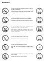
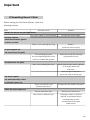
1
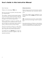
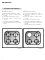
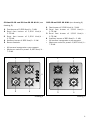
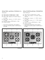
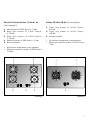
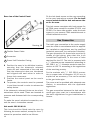
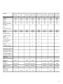
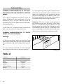
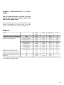
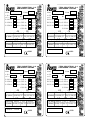
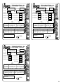
Installation and maintenance manual
COCINAS CRISTAL-GAS CG.1 4G / CG.1 3G. 1P
CG Lux-60 4G. / CG Lux-70 4G. / CG Lux-70 4G AI AL
CG Lux-70 5G. / CG Lux-60 4G. Al AL / CG Lux-70 5G. Al AL
CG Lux-70 5G AI TR AL / CG Lux-70 5G TR / CGC 4G / CGC 4G AI AL
CG Lux-75 2G AI TR AL / CG Lux-86 3G AI TR AL
CG Lux-86 2G 1P AI TR AL
User’s Guide to this Instruction Manual
Dear Customer,
Safety Instructions
Thank you for choosing a TEKA hob.
Before using your hob for the first time, please
read the installation and connection instructions.
We are sure that our product will fully satisfy
your requirements.
This modern, functional and practical appliance has been built using top quality materials
which are subjected to strict quality controls
throughout the manufacturing process.
Before installing or using our product, we
recommend you to carefully read this manual
and to follow its instructions step by step in
order to obtain the best possible results.
Keep this instruction manual in a safe place
so that you can consult it whenever necessar y
and comply with the warranty requirements.
To benefit from our Warranty you must present proof of purchase together with the
warranty cer tificate.
2
These hob models can be installed in the
same kitchen units as TEKA ovens and control
panels.
N.B. To avoid the risk of burns, keep children
away from the hob during or after its operation.
We recommend you to follow our instructions
and that the installation of our hobs be carried
out by our Technical Ser vice personnel only.
Contents
Introduction
Description of the Appliance
Page 4
4
Installation
Positioning of the hobs
Positioning of the oven
Anchoring of the hob
Connecting the hob to the oven or
the control panel
Gas Connection
Electrical Connection
Gas transformation
9
9
10
10
Technical Information
Dimensions and powers
Technical Data
Rating Plates
16
16
18
20
Use and Maintenance
Special requirements before first use
Component Par ts of Gas Burners
Lighting of Burners
Switching on Electric Hotplates
Components of a Safety System
Using your Hob
Hints for the correct Usage of Burners
Hints for the correct Usage of
Electric Hotplates
Reminder
Cleaning and Conservation
Electric Hotplates (Mod. CG. 1 3G 1P)
Maintenance
24
24
24
24
26
27
29
29
29
30
31
32
32
If Something Doesn´t Work
33
11
12
13
14
3
Introduction
Description of the Appliance
CG. 1 4G (see drawing 1)
CG.1 3G. 1P. (see drawing 2)
1 Auxiliary burner of 860 Kcal/h - 1 kW.
2 Semi fast burner of 1,500 Kcal/h 1.75 kW.
3 Fast burner of 2,550 Kcal/h - 3 kW
4 Semi fast burner of 1,500 Kcal/h 1.75 kW.
1 Auxiliary burner of 860 Kcal/h - 1 kW.
2 High -powe r hotp late of 1,5 00 W,
Ø 145 mm.
3 Semi fast burner of 1,500 Kcal/h 1.75 kW.
4 Fast burner of 2,550 Kcal/h - 3 kW.
• All burners incorporate a pan suppor t.
• Maximum calorific power: 6,400 Kcal/h 7.5 kW.
• All burners incorporate a pan suppor t.
• Maximum calorific power: 4,900 Kcal/h 5.75 kW.
• Maximum electric power: 1,500 Watts.
2
1
2
1
4
3
3
4
Drawing 1
4
Drawing 2
CG-Lux-60 4G. and CG Lux-60 4G AI AL (see
drawing 3)
1 Fast burner of 2,580 Kcal/h - 3 kW.
2 Semi fast burner of 1,500 Kcal/h 1.75 kW.
3 Semi fast burner of 1,500 Kcal/h 1.75 kW.
4 Auxiliar y burner of 860 Kcal/h - 1 kW.
5 Burner controls.
CGC 4G and CGC 4G AI AL (see drawing 4)
1 Fast burner of 2,580 Kcal/h - 3 kW.
2 Semi fast burner of 1,500 Kcal/h 1.75 kW.
3 Semi fast burner of 1,500 Kcal/h 1.75 kW.
4 Auxiliary burner of 860 Kcal/h - 1 kW.
• All burners incorporate a pan suppor t.
• Maximum calorific power: 6,450 Kcal/h 7.5 kW.
• All burners incorporate a pan suppor t.
• Maximum calorific power: 6,450 Kcal/h 7.5 kW.
1
3
1
2
3
4
5
2
4
Drawing 3
Drawing 4
5
CG-Lux-70 5G., and CG Lux -70 5G AI AL (See
drawing 5)
CG-Lux-70 5G TR and CG Lux -70 5G AI TR AL
(See drawing 6)
1 Fast burner of 2,580 Kcal/h - 3 kW.
2 Fast burner of 2,580 Kcal/h - 3 kW.
3 Semi fast burner of 1,500 Kcal/h 1.75 kW.
4 Semi fast burner of 1,500 Kcal/h 1.75 kW.
5 Auxiliary burner of 860 Kcal/h - 1 kW.
6 Burner controls.
1 Fast burner of 2,580 Kcal/h - 3 kW.
2 Triple ring burner of 3,000 Kcal/h
3.5 kW.
3 Semi fast burner of 1,500 Kcal/h
1.75 kW.
4 Semi fast burner of 1, 500 Kcal/h
1.75 kW.
5 Auxiliary burner of 860 Kcal/h - 1 kW.
6 Burner controls.
• All burners incorporate a pan support.
• Maximum calorific power: 9,450 Kcal/h
11 kW.
• All burners incorporate a pan suppor t.
• Maximum calorific power: 9,020 Kcal/h 10.5 kW.
1
2
4
6
3
5
Drawing 5
6
1
2
4
6
-
-
3
5
Drawing 6
CG-Lux-70 4G and CG Lux -70 4G AI AL
(See drawing 7)
1 Fast burner of 2,580 Kcal/h - 3 kW.
2 Semi fast burner of 1,500 Kcal/h 1.75 kW.
3 Semi fast burner of 1,500 Kcal/h 1.75 kW.
4 Auxiliar y burner of 860 Kcal/h - 1 kW.
5 Burner controls.
CG-Lux-75 2G AI TR AL (See drawing 8)
1 Triple ring burner of 3,010 Kcal/h 3.5 kW.
2 Triple ring burner of 3,010 Kcal/h 3.5 kW.
3 Burner controls.
• All burners incorporate a pan suppor t.
• Maximum calorific power: 6,020 Kcal/h 7 kW.
• All burners incorporate a pan support.
• Maximum calorific power: 6,450 Kcal/h 7.5 kW.
1
3
1
2
5
4
Drawing 7
2
3
Drawing 8
7
CG-Lux-86 3G AI TR AL (See drawing 9)
CG-Lux-86 2G 1P AI TR AL (See drawing 10)
1 Triple ring burner of 3,010 Kcal/h 3.5 kW.
2 Triple ring burner of 3,010 Kcal/h 3.5 kW.
3 Semi fast burner of 1,500 Kcal/h 1.75 kW.
4 Burner controls.
1
• All burners incorporate a pan suppor t.
• Maximum calorific power: 7,520 Kcal/h 8.75 kW.
1
3
2
• All burners incorporate a pan suppor t.
• Maximum calorific power: 6,020 Kcal/h 7 kW.
• Maximum electric power: 1,500 Watts.
1
4
3
2
4
Drawing 9
8
Triple ring burner of 3,010 Kcal/h 3.5 kW.
2 Triple ring burner of 3,010 Kcal/h 3.5 kW.
3 High-power hotplate of 1,500 W, Ø 145 mm.
4 Burner controls.
Drawing 10
Installation
Important
INSTALLATION AND ADJUSTMENT MUST BE
CARRIED OUT BY AUTHORISED TECHNICAL
PERSONNEL ACCORDING TO THE APPLICABLE
INSTALLATION REGULATIONS.
A
Positioning of the hobs
Depending on the model to be installed an aperture will be made in the worktop, of the dimensions specified in the drawing 11. A template is
included in the packaging of models CG.1 4G.
and CG.1 3G. 1P. for the correct sizing of the
aperture for these two hob models.
B
If the hob is installed above kitchen storage
units (cupboards, drawers, etc.), an intermediate panel must be fitted.
C
For hobs with controls, its location must
include a ventilation slot at the front, of 110
cm 2. In this case the minimum distance between the lower part of the hob and the upper
par t of the furniture below the hob will be 20
mm. If there is no front ventilation slot, the
minimum distance between the hob and the
upper par t of the furn i t u re must be 130
mm.The hob must be installed at least at 10
cm from its sides to any wall in the room.
D
E
The minimum ver tical distance of the lower
part of the piece of furniture placed above the
hob will be 600 mm.
The piece of furniture where the hob with oven
is to be placed will be properly fixed.
A
B
C
D
E
Mod.:
Mod.:
Mod.:
Mod.:
Mod.:
Drawing 11
CG Lux-60 y CGC 4G
CG.1 3G. 1P. y CG.1 4G.
CG Lux-70
CG Lux-75
CG Lux-86
* In the case of the granite hob the measurement can be 580 mm.
9
Positioning of the oven
In the cases of the models CG.1 4G and CG.1
3G 1P, the clamps must be fitted as shown in
the picture 13, depending on the thickness of
the furniture.
See the applicable manual.
Anchoring of the hob
Once the hob position has been dimensioned,
the seal (J) must be affixed to the lower part
of the cooker. This is fastened by means of
four clamps (G), each of which has two tabs
(P) which are inserted in the apertures (O) in
the hob until they click into place. To secure
the clamp, open the tab (S) outwards a little
as indicated in the figure. Once the seal and
the clamps have been positioned the appliance may be installed in its position.
For worktops 30 mm thick or less, use the M5
screws supplied as complementary fixation by
introducing them into the circular hole of the
clamp. A fillet shall form in this hole as the
screw is introduced in it. This operation should
be done before fastening the clamps to the hob.
20/30 mm.
Self-tapping screw for
worktops of 20 and 30
mm. wide
Use a screwdriver to tighten the screws (T) on
the four clamps and the hob will be perfectly
secured in place. (See drawing 12).
40 mm.
N.B. It is imperative to install the seal under
the brim of the worktop. Failure to install this
may cause the worktop to be exposed to high
temperatures.
Drawing 13
To install hob model CGC 4G AI AL, inser t the
quick-fix nuts in the screw housings (see drawing 14), connect the clip which corres
ponds with the height measurement of the
hob unit (20, 30 and 40 mm) and tighten the
screws until they are well secure.
J
S
A
B
O
O
20 mm.
30 mm.
40 mm.
G
P
C
D
E
Drawing 14
T
Drawing 12
10
A Seal
B Work top
D Fastening clip
C Screw
E Quick-fix nut
Hob models CG-Lux-75 2G and CG-Lux-86 3G
are installed in the same way as the CGC 4G
AI AL, except for the staples which are
geometrically dif ferent. The installation of
these hobs must be carried out in the way
shown in the drawing 15, depending on the
thickness of the work top.
B
A
20 mm.
30 mm.
40 mm.
Drawing 15
A Seal
C
B Work top
D Fastening clip
D
If the unit below the hob is to be used to store
products it must be situated at a distance of at
least 10 cm below the hob. Furthermore, it must
be taken into account that the temperature in
the interior of the furniture may rise to 60oC.
CONNECTING THE HOB TO THE OVEN
(Mod. CG.1 4G, CG.1 3G 1P and CGC 4G) OR
THE CONTROL PANEL
To connect the hob to the oven, four telescopic
universal joints are provided. (See drawing 17).
E
C Screw
A
E Quick-fix nut
CGC 4G
Once the hob position has been dimensioned,
the seal must be affixed (J) to the hob.
Fix the clamps (K) into the holes on the lower
part of the case, as shown in drawing, by tightening the four screws supplied (ø4.2 mm).
The clamps (K) and seal (J) are supplied in the
packaging along with the hob. (See drawing 16).
J
20
K
J
30
K
J
40
K
Drawing 16
A
B
Drawing 17
To make this connection, proceed as follows:
1 Disconnect from the mains supply (mod.
CG.1 3G 1P and CGC 4G AI AL).
2 Detach the telescopic universal joints by
pressing the retention tab (marked PUSH)
using a thin screwdriver and extract the
extender a few centimetres.
3 Remove the four lockpins from the ends (B).
4 Partially insert the oven in its position, taking
care not to snag the telescopic universal
joints which are hanging from the underside
of the hob, and leave sufficient space to be
able to connect the other ends of the joints
to the rods at the rear part of the control
panel, before finally connecting the lockpins.
5 For the electrical connection between the
two appliances, connect the hob connector
to the oven connector (mod. CG.1 3G 1P
and CGC 4G AI AL).
11
Rear view of the Control Panel:
1
Fix the hob knob covers on the oven according
to the oven instructions manual. Fix the knob
covers included with the hob and remove those for the oven.
This hob comes complete with knob covers for
all TEKA ovens except for models RT-600 and
RT-800. For these two models, order the knob
covers in your nearest TEKA establishment or
official technical service.
3
2
Gas Connection
Drawing 18
1 Flexible Power Cable.
2 Connector.
3 Power Unit Protective Casing.
6 Position the oven in its definitive location,
ensuring that the telescopic universal
joints are well connected to the rods and
that the telescopic tubes are introduced
well aligned with each other in order to
favour their movement.
7 Position the control panel on the oven’s
fascia.
8 To operate, the controls must be pressed
in and then turned in order to release the
safety device.
If the telescopic universal joints are too short,
extensions can be used. These are inserted at
pressure and fastened with the corresponding
cover.
To make the oven’s electrical connection, consult the oven’s instruction manual.
Hob model CGC 4G AI AL
This hob should be fitted onto the oven by
following the same method, except for item 7,
where the procedure shall be as follows:
12
The hob’s gas connection to the mains supply
must be made in accordance with the applicable installation regulations and by qualified
technical personnel (an authorized installer).
The gas connection for these hobs must be by
means of rigid piping, given that this is an
immobilized appliance, in the case of hobs
destined for the EC. The hob is prepared with
a 1/ 2 " diameter screw connection according to
ISO 228-1, or 1 /2 " diameter conical screw connection to ISO 7-1 according to the regulations
of the receiving country.
For the markets with 1 /2 " ISO 228-1 connection a copper tube of diameter 10/12 mm is
suplied as an accessory. This can be welded
to the gas intake pipe.
The room must be provided with adequate ventilation, in accordance with the applicable
regulations.
The gas connection between the hob and the
mains gas pipe must be in accordance with
the basic regulations for gas installations in
homes.
TEKA will not accept responsability for faults
or damage caused by incorrect or defective
instalation.
Once the gas connetion has been made the
air tightness of the installation mus be checked. If the check is made using air, the testing pre s s u re must be no greater than 200
g/cm 2 .
To avoid causing damage to the hob during
installation when tightenig the gas pipe connection nut, a maximum grip torque of 350
kg.f.cm must be used.
Elbow Union
Gasket
Straight
Hose Holder
Drawing 19
After installing the hob, check that the burners’ minimum settings are well regulated. To
do this, light the burners and check that they
do not go out when brusquely turned from
maximum to minimum.
Do not connect the hob burners with town gas
whose composition contains carbon monoxide, except in models which incorporate a
safety device.
Each time the gas connection nut is removed
the washer must be replaced.
The gas connection must be so sited that it is
not adversely heated when the appliance is in
operation.
When the gas hob has been installed, it is essential to check that neither the gas hose nor the
electric cable is in contact with hot parts of the
appliance or hot gas exhaust, other wise heat
damage to the hose and cable could occur.
When installation is completed, check that
all the gaskets are leaktight and any other
possible leak using a soap based solution,
never a flame.
Electrical Connection
(Only for cookers with automatic ignition or
with electric hotplates).
First of all it must be checked that the mains
voltage is the same as that indicated on the
appliance’s rating plate.
The connection must be made through an
omnipolar cut-off switch with a distance of at
least 3 mm between the contacts, assuring
disconnection in cases of emergency or for
the cleaning of the hob. It must also be provided with the correct earth connection in accordance with the applicable regulations.
If it comes necessar y to change the flexible
power cable in model CG.1 3G. 1P, the replacement must be carried out by TEKA’s official
Technical Ser vice as special tools are required. With the other hob models it is also
recommended that the replacement be carried
out by TEKA’s Techncial Service, though these
cables can be ordered from the Technical Service giving the reference CG Lux-60, CG Lux70, CG Lux-75, CG Lux-86 3G and CG Lux-86
2G 1P mains power cable, depending on the
model in question.
13
Gas transformation
Important!
The transformation of the appliance to use a
d i ff e rent gas to that for which it has been
sold must only be carried out by a qualified
technician.
Information for the Technical Service: in the
event of conversion of the type of gas or
pressure in the appliance, the new regulation
label must be placed over the existing one, in
order to identify the new characteristics after
the changeover.
To make the transformation replace the gas
nozzles and regulate the minimum settings of
the taps.
The gas nozzles necessar y for each type of
gas are indicated in table 1.
To replace the gas nozzles it is necessary to
follow the following instructions:
• Remove the pan suppor ts and the top par t
of the burners in order to access the nozzle.
• Use a no 7 tubular spanner to remove
th e no zz les a nd re pl ac e th em wi th th e
corresponding alternative nozzles. Take care
to tighten the nozzles well so as to avoid the
risk of gas leaks.
• Reposition the pan support and burner
covers.
Once the gas nozzles have been replaced, the
following instructions must be followed to
graduate the minimum settings.
Hob CG.1 4G, CG.1 3G 1P, CGC 4G y CGC 4G
AI AL
•
Remove the oven or the control panel from
their place to access the gas taps.
• Light the burners at their minimum setting.
• Use a small screw driver to remove the
screw on the right or centre of the plug of
the gas key (turn left for a big flame and
right for a small flame).
• Once the setting has been graduated
check that the flame remains at its minimum setting when the control is brusquely
t u rned between the maximum and the
minimum setting.
Table 1
CG LUX-60, CG LUX-70, CGC 4G, CG.1 4G, CG.1 3G. 1P.
CG Lux-75 and CG Lux-86
Burner
Family
First
Triple ring
Triple ring 5R (SHA)
Fast
Semi fast
Auxiliary
Group a
290
340
260
185
145
Group c
290
340
260
185
145
Gas nozzle diameter (Ø) expressed in 1/100 mm
14
Second
Group e
290
340
260
185
145
Group H
135
116
97
72
Group E+
135
116
97
72
Third
Group 3+
95
85
65
50
• In order to access the screw which graduates the gas flow through the taps in hob
CGC 4G AI AL, remove the screws that fix
the cover protecting the taps to the case
and lift the cover.
Others hobs
•
Remove the tap controls by pulling them
upwards strongly.
• Light the burners at their minimum setting.
• Use a small screw driver to remove the
screw on the right or centre of the plug of
the gas key (turn left for a big flame and
right for a small flame).
• Once the setting has been graduated
check the the flame remains at its minimum setting when the control is brusquely
t u rned between the maximum and the
minimum setting.
Models CG LUX-75 and CG LUX-86 regulated
for town gas can not be transformed to operate neither natural nor butane gas.
The only intervention necessar y for the transformation is the replacement of the gas nozzles and their setting.
TEKA INDUSTRIAL, S.A. will not accept
responsibility for incorrect hob operation if the
gas transformation and regulation of minimum
burner settings are not carried out by TEKA’s
official Technical Ser vice.
15
Technical information
Dimensions and powers
Models
Dimensions in mm
Length
Width
Depth
Glass thickness
Worktop
hob
dimensions mm.
Length
Width
3.5 kW Triple
ring gas burner
3 kW
fast burner
1.75 kW semi
fast burner
1 kW
auxiliary burner
1,000 W electric
hotplate Ø 145 mm.
1,500 W electric
hotplate Ø 145 mm.
1,500 W electric
hotplate Ø 180 mm.
CG.1 4G
CG.1 3G. 1P.
CG Lux-60
4G AI AL
CG Lux-60
4G.
CGC
4G
CGC 4G
AI AL
CG Lux-70
4G.
590
510
120
5
590
510
120
5
610
510
75
8
610
510
75
8
600
510
100
8
600
510
100
8
710
510
70
8
570
492
570
492
580
490
580
490
580
490
580
490
690
490
1
1
1
1
1
1
1
2
1
2
2
2
2
2
1
1
1
1
1
1
1
1
Electric
Maximum nominal
power W
Supply
voltage V
Frequency Hz
Gas
Maximum
power kW
16
7,5
1.500
0,6
0,6
230
50/60
220/240
50/60
220/240
50/60
5,75
7,5
7,5
7,5
7,5
7,5
Models
Dimensions in mm
Length
Width
Depth
Glass thickness
Worktop
hob
dimensions mm.
Length
Width
3.5 kW Triple
ring gas burner
3 kW
fast burner
1.75 kW semi
fast burner
1 kW
auxiliary burner
1,000 W electric
hotplate Ø 145 mm.
1,500 W electric
hotplate Ø 145 mm.
1,500 W electric
hotplate Ø 180 mm.
CG Lux-70 CG Lux-70 CG Lux-70 CG Lux-70 CG Lux-70 CG Lux-75 CG Lux-86 CG Lux-86
4G AI AL
5G.
5G AI AL 5G AI TR AL
5G. TR 2G AI TR AL 3G AI TR AL 2G 1P AI TR AL
710
510
70
8
710
510
70
8
710
510
70
8
710
510
70
8
710
510
70
8
750
450
70
8
860
450
70
8
860
450
70
8
690
490
690
490
690
490
690
490
690
490
670
350
815
405
815
405
1
1
2
2
2
1
2
2
1
1
2
2
2
2
2
1
1
1
1
1
1
Electric
Maximum nominal
power W
0,6
Supply
voltage V
220/240
Frequency Hz
50/60
Gas
Maximum
power kW
1
7,5
0,6
0,6
0,6
220/240 220/240
50/60
50/60
10,5
10,5
11
0,6
220/240 220/240
50/60
50/60
11
7
8,75
1.500
230
50/60
7
17
Technical Data
COMMON CHARACTERISTICS TO THE ELECTRIC HOTPLATES AND AUTOMATIC LIGHTING
MODEL
The supply voltage and frequency must be
those indicated in the rating plate. The fire
p rotection is of “X” type. The hob must be
installed at over 15 cm away from the side walls.
(See drawing 20).
In the event of a hotplate being cracked the
hob must be switched off at the mains.
c) “This appliance must not be connected to a
device for the evacuation of combustion products. Its installation and connection will be
carried out according the installation rules in force. Special attention will be paid to the applicable specifications concerning ventilation”.
Attention: The use of a gas cooking appliance, produces heat and humidity in the room
where it is installed. Good ventilation of the
kitchen must be ensured by keeping the natural ventilation holes open or by opening a window or installing an efficient mechanical ventilation device (mechanical ventilation hood).
COMMON CHARACTERISTICS TO EVERY
MODEL WITH GAS BURNERS
Warnings:
a) “Before installing, make sure that the local
distribution conditions (gas type and pressure)
are compatible with the setting of the appliance”.
b) “ The setting conditions, of this appliance
are printed on the label (or the rating plate)”.
Table 2
Country
Spain
Portugal
France
United Kingdom
Greece
18
Category
III1ace2H3+
II2H3+
II2E+3+
II2H3+
I3+
Drawing 20
COMMON CHARACTERISTICS TO EVERY
MODEL
N.B.: All the hob models referred to in this
manual have hot zones during or after their
use and can cause burns.
Care must be taken when handling these hobs
before installation as there may be rough
zones or corners which may be dangerous.
Table 3
Burner
Nominal calorific consumption
Nominal consumptions*
CCR CG Lux-60, CG Lux-70
CGC 4G, CG.1 4G and CG.1 3G. 1P
CCR CG Lux-75 and CG Lux-86
Efficiency
Triple
ring
Large
Standard
Small
kW
3,5
3
1,75
1
G-130 (Nm3/h)
0,49
0,42
0,24
0,14
G-150 (Nm3/h)
0,63
0,54
0,31
0,18
G-110 (Nm3/h)
G-20 (Nm3/h)
G-25 (Nm3/h)
G-30 (Kg/h)
G-31 (Kg/h)
0,79
0,33
0,38
0,25
0,24
0,68
0,29
0,33
0,22
0,21
0,40
0,17
0,19
0,13
0,13
0,23
0,10
0,11
0,07
0,07
kW
kW
%
1,55
1,55
>52
0,77
–
>52
0,47
0,47
>52
0,33
–
–
* On standard calorific power
19
TEKA INDUSTRIAL, S.A.
SANTANDER - ESPAÑA
CG.1 4G
Mod.
∑ Qn
(P.C.S.)
3
Clase
CG LUX 60 4G
Mod.
∑ Qn
Nº
7.50
TEKA INDUSTRIAL, S.A.
SANTANDER - ESPAÑA
(P.C.S.)
3
Clase
Nº
7.50
G-110 Vr
1.70 Nm3/h
G-20 Vr
0.71 Nm /h
G-110 Vr
1.70 Nm3/h
G-20 Vr
0.71 Nm3/h
G-130 Vr
1.05 Nm3/h
G-25 Vr
0.83 Nm3 /h
G-130 Vr
1.05 Nm3/h
G-25 Vr
0.83 Nm3/h
G-150 Vr
1.35 Nm3/h
G-30 Mr
0.55 Kg/h
G-150 Vr
1.35 Nm3/h
G-30 Mr
0.55 Kg/h
G-31 Mr
0.54 Kg/h
G-31 Mr
0.54 Kg/h
ES
3
FR
Cat. Kat III1ace2H3+
ES
II2E+3+
p (mbar) 8-18-28/37 20/25 28/37
Cat. Kat
GB
GR
II2H3+
I3+
Cat. Kat
H∆EKTPIKO
II2E+3+
p (mbar) 8-18-28/37 20/25 28/37
PT
II2H3+
p (mbar) 20-28/37 28/37 20-30/37
ELECT.
FR
Cat. Kat III1ace2H3+
GB
GR
II2H3+
I3+
PT
II2H3+
p (mbar) 20-28/37 28/37 20-30/37
ELECT.
H∆EKTPIKO
0099
0099
TYP. B1221300A
TYP. A1322100A
TEKA INDUSTRIAL, S.A.
SANTANDER - ESPAÑA
CG.1.3G.1P
Mod.
∑ Qn
(P.C.S.)
CG LUX 70 4G
Mod.
∑ Qn
Nº
5.75
G-110 Vr
3
Clase
TEKA INDUSTRIAL, S.A.
SANTANDER - ESPAÑA
(P.C.S.)
3
Clase
Nº
7.50
1.30 Nm3 /h
G-20 Vr
0.55 Nm3/h
G-110 Vr
1.70 Nm3/h
G-20 Vr
0.71 Nm3/h
G-130 Vr
0.80 Nm3 /h
G-25 Vr
0.64 Nm /h
G-130 Vr
1.05 Nm3/h
G-25 Vr
0.83 Nm3/h
G-150 Vr
1.03 Nm3/h
G-30 Mr
0.42 Kg/h
G-150 Vr
1.35 Nm3/h
G-30 Mr
0.55 Kg/h
G-31 Mr
0.41 Kg/h
G-31 Mr
0.54 Kg/h
ES
3
FR
Cat. Kat III1ace2H3+
ES
II2E+3+
p (mbar) 8-18-28/37 20/25 28/37
Cat. Kat
GB
GR
II2H3+
I3+
p (mbar) 20-28/37 28/37 20-30/37
ELECT.
H∆EKTPIKO
220…230 V ~
50/60 Hz. 1.500 W
TYP. B1D21300A
20
II2E+3+
p (mbar) 8-18-28/37 20/25 28/37
PT
II2H3+
FR
Cat. Kat III1ace2H3+
Cat. Kat
GB
GR
II2H3+
I3+
PT
II2H3+
p (mbar) 20-28/37 28/37 20-30/37
ELECT.
H∆EKTPIKO
0099
0099
TYP. A1322100A
TEKA INDUSTRIAL, S.A.
SANTANDER - ESPAÑA
Mod.
∑ Qn
(P.C.S.)
CG LUX 70 5G
3
Clase
Mod.
∑ Qn
Nº
10.5
TEKA INDUSTRIAL, S.A.
SANTANDER - ESPAÑA
(P.C.S.)
CG LUX 70 5G AI AL
CG LUX 70 5G AI
3
Clase
Nº
10.5
G-110 Vr
2.38 Nm3 /h
G-20 Vr
1.00 Nm /h
G-110 Vr
2.38 Nm 3/h
G-20 Vr
1.00 Nm 3/h
G-130 Vr
1.47 Nm3 /h
G-25 Vr
1.16 Nm3/h
G-130 Vr
1.47 Nm 3/h
G-25 Vr
1.16 Nm 3/h
G-150 Vr
1.89 Nm3/h
G-30 Mr
0.77 Kg/h
G-150 Vr
1.89 Nm3 /h
G-30 Mr
0.77 Kg/h
G-31 Mr
0.75 Kg/h
G-31 Mr
0.75 Kg/h
ES
3
FR
Cat. Kat III1ace2H3+
ES
II2E+3+
p (mbar) 8-18-28/37 20/25 28/37
Cat. Kat
GB
GR
II2H3+
I3+
p (mbar) 20-28/37 28/37 20-30/37
ELECT.
H∆EKTPIKO
Cat. Kat
TYP. A1323210A
GB
GR
II2H3+
I3+
PT
II2H3+
p (mbar) 20-28/37 28/37 20-30/37
ELECT.
0099
II2E+3+
p (mbar) 8-18-28/37 20/25 28/37
PT
II2H3+
FR
Cat. Kat III1ace2H3+
H∆EKTPIKO
220…240 V ~
50/60 Hz.
0,6 W
0099
TYP. A1323210I
TEKA INDUSTRIAL, S.A.
SANTANDER - ESPAÑA
Mod.
∑ Qn
(P.C.S.)
CG LUX 60 4G AI AL
CG LUX 60 4G AI
3
Clase
Nº
7.50
G-110 Vr
1.70 Nm3/h
G-20 Vr
0.71 Nm3/h
G-130 Vr
1.05 Nm3/h
G-25 Vr
0.83 Nm3/h
G-150 Vr
1.35 Nm3 /h
G-30 Mr
0.55 Kg/h
G-31 Mr
0.54 Kg/h
ES
FR
Cat. Kat III1ace2H3+
II2E+3+
p (mbar) 8-18-28/37 20/25 28/37
Cat. Kat
GB
GR
II2H3+
I3+
PT
II2H3+
p (mbar) 20-28/37 28/37 20-30/37
ELECT.
H∆EKTPIKO
220…240 V ~
50/60 Hz.
0,6 W
0099
TYP. A1322100I
21
TEKA INDUSTRIAL, S.A.
SANTANDER - ESPAÑA
TEKA INDUSTRIAL, S.A.
SANTANDER - ESPAÑA
Mod.
∑ Qn
(P.C.S.)
CG LUX 70 4G AI AL
CG LUX 70 4G AI
3
Clase
∑ Qn
Nº
7.50
CGC 4G
Mod.
(P.C.S.)
3
Clase
Nº
7.50
G-110 Vr
1.70 Nm3/h
G-20 Vr
0.71 Nm3/h
G-110 Vr
1.70 Nm3 /h
G-20 Vr
0.71 Nm 3/h
G-130 Vr
1.05 Nm3/h
G-25 Vr
0.83 Nm3/h
G-130 Vr
1.05 Nm 3/h
G-25 Vr
0.83 Nm 3/h
G-150 Vr
1.35 Nm3/h
G-30 Mr
0.55 Kg/h
G-150 Vr
1.35 Nm 3/h
G-30 Mr
0.55 Kg/h
G-31 Mr
0.54 Kg/h
G-31 Mr
0.54 Kg/h
ES
ES
FR
Cat. Kat III1ace2H3+
p (mbar) 8-18-28/37 20/25 28/37
Cat. Kat
GB
GR
II2H3+
I3+
Cat. Kat
GB
GR
II2H3+
I3+
H∆EKTPIKO
0,6 W
0099
0099
TYP. B1322100A
TYP. A1322100I
TEKA INDUSTRIAL, S.A.
SANTANDER - ESPAÑA
Mod.
CG LUX 70 5G TR
∑ Qn
(P.C.S.)
G-110 Vr
PT
II2H3+
p (mbar) 20-28/37 28/37 20-30/37
ELECT.
H∆EKTPIKO
220…240 V ~
50/60 Hz.
II2E+3+
p (mbar) 8-18-28/37 20/25 28/37
PT
II2H3+
p (mbar) 20-28/37 28/37 20-30/37
ELECT.
FR
Cat. Kat III1ace2H3+
II2E+3+
3
Clase
CGC 4G AI AL
Mod.
∑ Qn
Nº
11
TEKA INDUSTRIAL, S.A.
SANTANDER - ESPAÑA
(P.C.S.)
3
Clase
Nº
7.50
2.5 Nm3 /h
G-20 Vr
1.04 Nm3/h
G-110 Vr
1.70 Nm3/h
G-20 Vr
0.71 Nm3/h
G-130 Vr
1.54 Nm3/h
G-25 Vr
1.22 Nm /h
G-130 Vr
1.05 Nm3/h
G-25 Vr
0.83 Nm3/h
G-150 Vr
1.98 Nm3/h
G-30 Mr
0.81 Kg/h
G-150 Vr
1.35 Nm3/h
G-30 Mr
0.55 Kg/h
G-31 Mr
0.80 Kg/h
G-31 Mr
0.54 Kg/h
ES
3
FR
Cat. Kat III1ace2H3+
ES
II2E+3+
p (mbar) 8-18-28/37 20/25 28/37
Cat. Kat
GB
GR
II2H3+
I3+
p (mbar) 20-28/37 28/37 20-30/37
ELECT.
H∆EKTPIKO
TYP. A1324210A
22
Cat. Kat
GB
GR
II2H3+
I3+
PT
II2H3+
p (mbar) 20-28/37 28/37 20-30/37
ELECT.
0099
II2E+3+
p (mbar) 8-18-28/37 20/25 28/37
PT
II2H3+
FR
Cat. Kat III1ace2H3+
H∆EKTPIKO
220…240 V ~
50/60 Hz.
TYP. A1324210A
0,6 W
0099
TEKA INDUSTRIAL, S.A.
SANTANDER - ESPAÑA
Mod.
CG LUX 70 5G AITR AL
CG LUX 70 AI TR
∑ Qn
Mod.
CG LUX 75 2G AI TR AL
CG LUX 75 2G AI TR
∑ Qn
Nº
11
(P.C.S.)
3
Clase
TEKA INDUSTRIAL, S.A.
SANTANDER - ESPAÑA
Nº
7
(P.C.S.)
3
Clase
G-110 Vr
2.50 Nm3/h
G-20 Vr
1.04 Nm /h
G-110 Vr
1.59 Nm3/h
G-20 Vr
0.66 Nm3/h
G-130 Vr
1.54 Nm3/h
G-25 Vr
1.22 Nm 3/h
G-130 Vr
0.98 Nm3/h
G-25 Vr
0.77 Nm3/h
G-150 Vr
1.98 Nm3 /h
G-30 Mr
0.81 Kg/h
G-150 Vr
1.26 Nm3/h
G-30 Mr
0.51 Kg/h
G-31 Mr
0.80 Kg/h
G-31 Mr
0.50 Kg/h
ES
3
FR
Cat. Kat III1ace2H3+
ES
II2E+3+
p (mbar) 8-18-28/37 20/25 28/37
Cat. Kat
GB
GR
II2H3+
I3+
Cat. Kat
H∆EKTPIKO
220…240 V ~
50/60 Hz.
GB
GR
II2H3+
I3+
H∆EKTPIKO
220…240 V
50/60 Hz.
0099
TYP. A1324210I
~
0,6 W
∑ Qn
(P.C.S.)
CG LUX 86 3G AI TR AL
CG LUX 86 3G AI TR Clase
3
TEKA INDUSTRIAL, S.A.
SANTANDER - ESPAÑA
Mod.
3
CG LUX 86 2G 1PAI TR AL Clase
∑ Qn
Nº
8.75
G-110 Vr
0099
TYP. A1404000I
TEKA INDUSTRIAL, S.A.
SANTANDER - ESPAÑA
Mod.
PT
II2H3+
p (mbar) 20-28/37 28/37 20-30/37
ELECT.
0,6 W
II2E+3+
p (mbar) 8-18-28/37 20/25 28/37
PT
II2H3+
p (mbar) 20-28/37 28/37 20-30/37
ELECT.
FR
Cat. Kat III1ace2H3+
(P.C.S.)
Nº
7
1.98 Nm3/h
G-20 Vr
0.83 Nm 3/h
G-110 Vr
1.59 Nm 3/h
G-20 Vr
0.66 Nm3/h
G-130 Vr
1.22 Nm3/h
G-25 Vr
0.97 Nm /h
G-130 Vr
0.98 Nm 3/h
G-25 Vr
0.77 Nm3/h
G-150 Vr
1.57 Nm3/h
G-30 Mr
0.64 Kg/h
G-150 Vr
1.26 Nm3 /h
G-30 Mr
0.51 Kg/h
G-31 Mr
0.63 Kg/h
G-31 Mr
0.50 Kg/h
ES
3
FR
Cat. Kat. III1ace2H3+
ES
II2E+3+
p (mbar) 8-18-28/37 20/25 28/37
Cat. Kat.
GB
GR
II2H3+
I3+
p (mbar) 20-28/37 28/37 20-30/37
ELECT.
H∆EKTPIKO
220…240 V
50/60 Hz.
TYP. A1042004I
~
0,6 W
Cat. Kat.
GB
GR
II2H3+
I3+
PT
II2H3+
p (mbar) 20-28/37 28/37 20-30/37
ELECT.
0099
II2E+3+
p (mbar) 8-18-28/37 20/25 28/37
PT
II2H3+
FR
Cat. Kat. III1ace2H3+
H∆EKTPIKO
230 V
50/60 Hz.
~
1.500 W
0099
TYP. A1E04E04LE
23
Use and Maintenance
Special requirements
before first use
Before connecting the hob to the power supply
check that the voltage and frequency are those indicated in the rating plate located on the
lower par t of the hob.
Remove the protecting plastic af fixed to the
hob, if any.
N.B. Each time you assemble a burner, check
that all of its component parts fit together
correctly. A badly positioned component may
cause the hob glass to overheat.
Lighting of burners
For hobs models CGC 4G, CG.1 4G. and CG.1
3G. 1P. (See drawing 22).
• Check that the controls are in the correct
position.
Component Parts of Gas Burners
• Open the mains connection gas tap or the
gas bottle cock.
A
B
C
• Put a lit match, lighter or flame, etc. next
to the burner if no automatic lighting is
available.
While keeping the burner control pressed, turn
it in anti-clockwise direction as far as it will go
until the maximum setting (large flame “C”).
The burner operates at that moment at full
power. Then, if desired, turn the control to the
minimum position (small flame “D”).
D
A
E
B
C
F
E
Drawing 21
A Pan suppor t supplement
B Pan support
C Burner cover
D Burner head
E Gas nozzle
F Nozzle unit
Drawing 22
A Burner indicator
B Setting indicator
C Off setting
D Minimun gas setting
E Maximun gas setting
24
D
For hobs CG Lux-60, CG Lux-70, CG Lux-75
and CG Lux-86, which have automatic ignition and a safety feature, the following steps
should be followed: (See drawing 23)
• Check that the controls are in the correct
position.
• Open the mains connection gas tap or the
gas bottle cock.
• Press the burner control.
• While keeping the burner control pressed,
turn it as far as it will go until the gas ignites. Keep pressed for 5 to 10 seconds, in
order to permit the safety thermocouple to
be activated.
• Turn the control to the desired position.
• Check that the control knobs are in the
appropriate position.
• Open the gas flow key or the gas cylinder
key.
• Press the control knob and turn it at the
same time in anti-clockwise direction as far
as it will go to the ignition setting (ignition
illustration). Once gas has been lit, keep
the control knob at this setting for 5 to 10
seconds to let the safety thermocouple act.
• Set the control knob to the desired position.
A
B
C
D
The ignition unit (ceramic and electrode)
must be carefully cleaned at regular intervals
in order to prevent ignition problems. Also
check that the burner apertures are not obstructed.
A
B
F
A
B
C
D
E
F
E
Drawing 24
Burner indicator
Setting indicator
Off setting
Minimum gas setting
Maximum gas setting
On burner setting
For safety reasons we recommend that the
gas supply tap should be turned off when the
cooker is not in use, in accordance with gas
supply company instructions.
C
D
Drawing 23
A Burner pilot lamp
B Control off position
C Maximum gas position
If you smell gas, turn off the hob’s gas supply
tap and ventilate the room. The gas installation and the hob must be checked by a specialized technician.
Warning:
D Minimum gas position
Follow the instructions below in order to operate a CGC 4G AI AL hob: (See drawing 24)
To avoid the risk of burns, keep children away
from the hob during or after its operation.
25
Use flat bottomed pans and check that they
are placed correctly on the pan suppor t, in
order to prevent pans from sliding when their
contents star t to boil (do not use pans with
concave or convex bases).
The red-point hotplate (1,500 W) heats up
especially quickly and at its maximum power
during approximately the first five minutes.
After this time its power drops to 500 W and it
conser ves the same temperature.
Hob models CG-Lux-75 and CG-Lux-86 are
provided with a special pan suppor t which
permits the use of concave-bottom pans
(woks).
The control panel features a square drawing containing circles beside each control knob, indicating to which hotplate the control corresponds.
The minimum diameter of the pans to be used
is 140 mm. For pans of 120 mm diameter or
less, use the small burner with the pan support supplement.
On the same panel there is a pilot light which
indicates the operation of one or more hotplates.
B
A
Switching on Electric Hotplates
The electric hotplates are controlled by a
seven step switch. To obtain different powers
the corresponding control must be turned to
the desired setting. (See drawing 25).
The pan should be placed on the electric hotplate before it is switched on.
The powers corresponding to each setting of
the control knob are shown in the following
table:
Hotplate Ø 145 – 1500 W.
Control at
Power
0
Disconnected
1
135 W.
2
165 W.
3
250 W.
4
500 W.
5
750 W.
6
1500 W.
These hobs have zones which become hot
during and after their use and can cause
burns.
26
C
A
Hotplate operation pilot
B
Control indicator
C
Pilot light
Drawing 25
When connecting the hotplate for the first time,
or if the plate has not been used in a long time,
it is necessar y to dr y out any humidity which
may have been absorbed by the insulation. To
achieve this, switch the hotplate on, without
any pan, for five minutes at power position 2.
TEKA Industrial, S.A. will accept no responsibility for possible inaccuracies contained in
this instruction manual due to transcription or
printing errors.
It also reser ves the right to make any modifications it considers necessary or useful to its
appliances without affecting their essential
characteristics.
Components of a Safety System
On all the hobs which incorporate the safety
feature (models with initials AL), the gas cutoff system is comprised formed by the following elements: (See drawing 26).
G
C
F
A
• Safety tap
• Safety thermocouple next to the burner
• Thermocouple-tap connection
B
E
D
Drawing 26
The thermocouple sends an electrical signal to
the tap, detecting the presence or absence of
a flame at the burner. During ignition the tap
must be kept pressed in for 5 to 10 seconds
until the thermocouple heats up and sends
the flame confirmation signal to the tap. If the
flame goes out, its absence is detected by the
thermocouple and the safety tap cuts off the
supply of gas.
A Safety thermocouple
B Thermocouple-tap connection
C Connection to the sparking unit
D Sparking unit
E Ceramic head
F Electrode
G Safety tap
27
Using your Hob
• Do not use the glass surface as a storage
area.
• Do not put aluminium plates, tinfoil or plastics on the glass surface.
• On hobs which have five burners, pans of
l a rge diameters must always be placed
on the central burner in order to prevent
heat from being reflected onto the worktop. On hobs with four burners you should
use the pan suppor t supplement with this
type of pan.
A
Drawing 27
•
When cooking with a griddle pan, stoneware pots or pans which reflect heat downwards, you must use the pan support supplement, other wise the excessive
temperature which is reflected downwards
may damage the hob glass or the burners.
• The pan suppor t supplement can be used
to cook with pans of small diameters,
when ver y little heat is needed, to cook
very slowly, or to keep food warm. Burner
efficiency is lost when the pan support
supplement is used.
• If you detect any breakage or cracking in
the hob glass, switch all the burner controls to the of f position (‘0’), turn of f the
gas connection and disconnect the electricity supply. Contact your TEKA Technical
Service.
28
B
Drawing 28
A
Griddle pan, stoneware pots or pans
which reflect heat downwards
B
Pan support supplement
Suggestions and Recommendations
Hints for the Correct Usage
of Burners
• Do not use large burners with pans of
small diameters as par t of the flame will
be deflected around the outside of the
pan, thus considerably reducing efficiency.
(See drawing 29)
A
hob, in order to prevent deflected flames
from damaging worktops with plastic surfaces.
Hints for the Correct Usage
of Electric Hotplates
For maximum ef ficiency with electric hotplates, follow these guidelines:
• Use pans with totally flat bottoms. The greater the area in contact with the plate, the
greater the transmission of heat. Pans with
thick bottoms are recommended as these
are more resistant to denting. Notice in the
figure 30 how the contact area is smaller
when the pan bottom is dented or warped.
B
Drawing 29
A Right
B Wrong
• Lit burners must not be left uncovered, in
order to avoid the wastage of gas and to
prevent the excessive heating of the pan
support.
• When the burners are lit they must not be
exposed to strong drafts. As well as reducing their calorific power there is a risk
that the flame may be blown out, leading
to gas leaks which could cause an accident. Care should be taken in this re spect par ticularly when burners are operating at a low setting.
• If the burner causes the blackening of
pans, or if the points of the flames are
yellow, it needs to be cleaned. If this fault
persists, get in touch with your Technical
Service to adjust the primary air setting or
to clean the gas pipe.
• Do not use cast iron pans directly on the
pan support as they reflect excessive heat
towards the hob.
• Pans placed on the burners must not be
allowed to protrude over the edges of the
A
A Right
B
B Wrong
B
Drawing 30
• Do not use pans whose diameter is smaller than that of the hotplate. This avoids
the risk of boiling food spilling onto the
hotplate.
• Dr y the bottom of all pans before placing
them on the electric hotplates.
• When you have almost finished cooking it
is recommended to switch the hotplate to
its minimum setting or to switch it off completely a few moments before removing the
pan. This allows use to be made of storedup energy and prevents the hotplate from
working without a load.
NEVER LEAVE AN ELECTRIC HOTPLATE
UNCOVERED
29
Reminder
Do not use small pans on large burners, as the flame will be dissipated.
Use appropriately sized pans for each burner, thus
making the best use of the heat.
Do not place pans unevenly on the pan support.
Place the pan correctly over the centre of the burner.
Do not use pans which reflect excessive heat
downwards directly on the pan support.
When using a griddle pan, stoneware pots or pans
which reflect heat downwards, always use the pan
support supplement.
Do not place pans directly on the burner.
Always place pans on the pan support.
Do not use sharp objects on the hob.
After use, pan suppor ts should be cleaned when
cold.
Avoid excessive weights or blows to the hob with
heavy objects.
Handle pans with care on the cooker.
30
Cleaning and Conservation
For the correct conser vation of the hob glass
it must be cleaned using the appropriate products and utensils and when the glass is
cold. Cleaning is easier if it is done each
time the hob is used, thus preventing the
build-up of dir t.
The cleaning of the hob glass will depend on
its degree of dirtiness:
• When the hob is only slightly dir ty and the
dirt is not adhered, clean with a damp
cloth and mild detergent.
• Stains or grease should be removed using
cleaning products suitable for glass (ceramic cleaners).
• When dirt is strongly adhered or burnt-on,
it should be removed by scraping with a
razor blade.
• If plastic objects/utensils or sugar has
melted on the sur face of the glass, these
should be scraped off immediately, before
the glass cools off.
• Under no circumstances should aggressive
or abrasive cleaning products, such as
oven cleaners, deoxidizing stain removers,
sponges with hard sur faces or scourers,
be used.
• Do not slide pans across the glass. This
may cause scratching.
• Take care to prevent pans from boiling dr y.
The heat accumulated in the bottom of the
pan could cause damage to the burner or
to the hob glass.
• The hob glass will withstand light blows by
large pans which do not have sharp edges.
Care should be taken to avoid impacts by
small sharp utensils. Do not strike the
edge of the glass with pans as this may
cause irreparable damage.
• Do not spill cold liquids on the glass or the
burners when they are hot.
• Do not stand or lean on the glass. It may
break and cause injur y.
Cleaning and conservation of other elements:
• Pan supports should be cleaned with a
non-abrasive scourer after they have cooled off.
• Burners must be cleaned periodically, particularly the grooves in the burner heads.
This is achieved by soaking in warm soapy
water and scrubbing with a scourer or a
stiff brush.
• Do not clean the enamelled burner covers
when they are still hot. Damage can be
caused by abrasive products, such as vinegar, coffee, milk, salt water and tomato juice, as a result of prolonged contact with
the enamelled surfaces.
• Stainless steel must be washed with
soapy water and a soft cloth. If the surface
continues to be yellow after washing we
recommend the use of lemon, vinegar, diluted bleach or a cleaning product which contains bleach. The shine of stainless steel
is maintained by lightly buffing with a
metal polish.
• The control panel should be cleaned with
soapy water and a soft cloth.
• When the burners have been dismantled
for cleaning purposes, care should be
taken to prevent liquids or other objects
from entering the nozzle unit.
• Do not use cleaning products which are
aggressive to aluminium, such as caustic
soda, oil, etc.
• Each time you assemble a burner, check
that all of its component parts fit together
correctly. A badly positioned element may
cause the hob glass to overheat.
31
Electric Hotplates
(Mod. CG.1 3G. 1P.)
Maintenance
Before cleaning, disconnect the appliance
from the mains supply.
No part of this appliance requires period lubrication, though the gas tap cones should be
kept clean and well greased.
Electric hotplates should be cleaned with
soapy water and a non-abrasive scourer. If,
after cooking, the stainless steel ring of the
hotplate or cooker frame is seem to be slightly
yellow, this may be cleaned using lemon, vinegar, diluted bleach or any cleaning product
which contains bleach.
Each time the gas taps are dismantled, the
washer which connects them with the distribution pipe should be replaced.
Do not clean the hotplates when they are still
hot.
The burners are operating correctly when their
flame is stable and of a blue-green colour. If
the points of the flame are yellow the burners
should be well cleaned. If the problem persists, contact your Technical Service.
If any liquid is spilt on the hotplates this
should be removed instantly with a dr y cloth.
Never allow remains of food to carbonize on
the hotplate as this will reduce its heat transmission capacity.
To guarantee the airtightness of the gas installation and the correct operation of the burners, the hob must be serviced by the specialized Technical Service at least once ever y
four years.
After using the hotplate it must be greased, leaving its surface shiny and preventing rusting.
N.B.
To extend the lifetime of the hotplate, excessive humidity or temperature should be avoided
where possible.
Steam appliances must not be used to clean
the heating plate.
32
Any required modification or setting of the
appliance must be carried out by authorized
technical personnel.
Important
If Something Doesn’t Work
Before calling the Technical Service, make the
following checks:
Fault
Possible Cause
Neither the hob nor the pilot light works.
The mains cable is not connected.
No spark appears
when the automatic ignition
switch is pressed.
Power is not reaching the plug.
Solution
Connect the mains cable.
Check /
repair the mains supply.
A spark appears but
the burner does not ignite.
The sparking plug and
the corresponding burner zone
is dirty or coated with grease.
Clean the end of the sparking
plug and the burner.
Gas is not reaching the hob.
Check that the gas bottle regulator
is correctly positioned
and open.
Open the gas connection
tap in the case of mains gas.
There is no flame in the
thermocouple zone.
The gas burners blacken the pans.
Burner apertures dirty.
Gas nozzle or diffuser dirty.
Clean burner apertures.
Clean gas nozzle or diffuser
without using objects which
could damage or alter
the diameter of the gas
outlet orifice.
The burners do not ignite.
The burner ignites
but when the safety switchis released it goes out.
Clean the burner apertures.
33
TEKA GROUP
COUNTRY
CITY
COMPANY
CC
PHONE
FAX
Austria
Belgium
Chile
China
Czech Republic
France
Greece
Hungary
Indonesia
Malaysia
Wien
Zellik
Santiago de Chile
Shanghai
Brno
Paris
Athens
Budapest
Jakarta
Kuala Lumpur
43
32
56
86
42
33
30
36
62
1 - 86680 - 20
2466 - 8740
2 - 273.19.45
21 - 6236 - 2375
05 - 4921 - 0479
1 - 4891 - 3788
10 - 9760283
1 - 354.21.10
21 - 39052 - 74
1 - 86680 - 82
2446 - 7687
2 - 273.10.88
21 - 6236-2379
05 - 4921 - 0479
1 - 4891 - 2973
10 - 9712725
1 - 354.21.15
21 - 39052 - 79
Mexico
Poland
Portugal
Singapore
Thailand
The Netherlands
Turkey
U.K.
U.S.A
Venezuela
Mexico D.F.
Warszawa
Ilhavo
Singapore
Bangkok
Zoetermeer
Istanbul
Abingdon
Tampa
Caracas
KÜPPERSBUSCH GES.M.B.H.
B.V.B.A. KÜPPERSBUSCH S.P.R.L.
TEKA CHILE S.A.
TEKA CHINA LTD.
TEKA-SWIAG S.R.O.
TEKA FRANCE S.A.R.L .
TEKA HELLAS S.A.
TEKA HUNGARY KFT.
P.T. TEKA BUANA
TEKA KÜCHENTECHNIK
(MALAYSIA) SDN.BHD.
TEKA MEXICANA S.A. DE C.V.
TEKA POLSKA SP. Z O O.
TEKA PORTUGUESA LTDA.
TEKA SINGAPORE PTE. LTD.
TEKA (THAILAND) CO. LTD.
TEKA BV
TEKA TEKNIK MUTFAK A.S.
TEKA PRODUCTS (UK) LTD.
TEKA USA, INC
TEKA ANDINA, S.A.
60
52
48
351
65
66
31
90
44
1
58
3 - 762.01.600
555 - 762.04.90
22 - 652.18.94
234.32.95.00
6 - 73 - 42415
2 - 5164954
79 - 345.15.89
212 - 274.61.04
1235 - 86.19.16
800 - 419 - 9344
2 - 291.28.21
3 - 762.01.626
555 - 762.05.17
22 - 850.12.48
234.32.54.57
6 - 73 - 46881
2 - 9021484
79 - 345.15384
212 - 274.56.86
1235 - 83.21.37
813 - 228 - 8604
2 - 291.28.25
KÜCHENTECHNIK
Teka Industrial, S. A.
Teka Küchentechnlk GmbH
Cajo, 17
39011 SANTANDER (SPAIN)
Tel.: 34 - 942 35 50 50
Fax: 34 - 942 34 76 94
http://www.teka.net
Sechsheldener Str. 122
35708 Haiger (Germany)
Tel.: 49 - 2771 - 8141-0
Fax: 49 - 2771 - 8141-10
http://www.teka.net