1
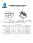
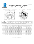
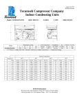
March 7, 2011 Tecumseh Compressor Company Indoor Condensing Units Model: AWG4520CXNXM BoM: 2B3271-1 R407C 1.5 HP AIRCOOLED Dimensions, inches Line Connection* Pumpdown Air L W H CH Suction Liquid SCFM 90 F 90% 25.0 33.48 19.5 -7/8” S 3/8” S 14.73 lbs 1750 AWG4520CXNXM * F = Flare, S = Solder, RF or RS = Rotolock with Flare or Solder Connections, C = Compression Fitting Model Oil Ch Oz. 38 Gr. Wt. Lbs. 195 Ambient Temperatures Evaporator T, 80°F 90°F 100°F 110°F °F PSIG BTUH Watts Cond T BTUH Watts Cond T BTUH Watts Cond T BTUH Watts Cond T 5 23.5 7327 1227 86 6402 1266 97 6000 1289 108 1628 1289.2 118 10 27.9 8574 1327 87 7503 1360 98 6667 1379 108 3231 1388 118 15 32.7 9998 1425 88 8781 1454 98 7567 1473 109 4873 1480 119 20 37.9 11597 1521 89 10237 1550 99 8700 1571 109 6554 1578 119 25 43.6 13372 1615 90 11870 1646 100 10066 1672 110 8273 1680 120 30 49.6 15322 1706 91 13681 1743 101 11665 1777 111 10031 1788 121 35 56.1 17448 1795 93 15669 1841 102 13496 1886 112 11828 1900 122 40 63.2 19749 1882 94 17834 1940 104 15561 1999 114 13664 2018 123 45 70.7 22226 1966 96 20177 2039 105 17858 2115 115 15538 2140 125 50 78.8 24879 2048.1 98 22698 2139.3 107 20388 2235 116.99 17451 2267.5 126 55 87.9 27707 2128 100 25396 2240 109 23152 2358 119 19403 2400 128 60 Hz Performance Return gas temp. 65F, 5F sub cooling March 7, 2011 Specifications/ Parts: Model Unit Bill of Material Nominal Volts-Hz-Ph Refrigeration Range Design Pressure Low Design Pressure High Voltage Range Min. Circuit Ampacity Max. Fuse Size (amps) Compressor Model Comp. Bill of Material Compressor RLA/LRA Overload Relay Run Capacitor Run Capacitor Rating Start Capacitor Start Capacitor Rating Contactor Unit Drawing Wiring Diagram AWG4520CXNXM 2B3271-1 208-230-60-1 20° to 55° 150 450 180 to 254 13.3 20 AWG5518CXN AW703GT-099-P2 9.4 / 52 INTERNAL 820ARR3H23 85PR370F20 25MFD 370V(M) VDE 85PS330D17 145-175 MFD 330V VDE N/A DGU1918-1 91028 Fan Motor Fan Motor RLA Fan Blade Fan Guard Fan Shroud High Pressure Switch Low Pressure Control Fan Switch 1 Condenser Headmaster Valve * Fan Switch 2 Receiver Tank Liquid Valve Liquid Filter * Sight Glass * Suction Valve Rotolock Valve Gasket Discharge Valve * Suction Filter * Accumulator Crankcase Heater * Defrost Timer * * = Outdoor Units Only Options for Outdoor Units Receiver Heater Solenoid Valve Electrical Wiring Diagram 810F050C20 (2) 0.70 51568-1 (2) 70831 (2) 70648-2 84095-1 84026-2 84096-1 50858 N/A 84096-2 51081-1 31581-1 N/A N/A N/A N/A N/A N/A TK00042000 91022-1 N/A N/A N/A