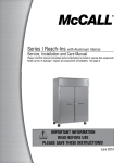
1
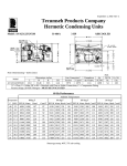
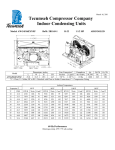
March 16, 2011 Tecumseh Compressor Company Indoor Condensing Units Model: AWA2490ZXDXF BoM: 2C2154-1 R-404A 2.25 HP AIRCOOLED Dimensions, inches Line Connection* Pumpdown Air L W H CH Suction Liquid 90 F 90% SCFM 25.0 33.5 19.5 14.7 7/8” S 3/8” S 16.46 lbs 1850 AWA2490ZXDXF * F = Flare, S = Solder, RF or RS = Rotolock with Flare or Solder Connections, C = Compression Fitting Model Oil Ch Oz. 38.5 Gr. Wt. Lbs. 200 Ambient Temperatures Evaporator T 80F 90F 100F 110F °F PSIG BTUH Watts Cond T BTUH Watts Cond T BTUH Watts Cond T BTUH Watts Cond T -30 10.7 5090 1533 88 4098 1492 97 3565 1468 107 --- --- --- -25 14.0 6269 1676 89 5212 1650 98 4420 1622 108 3571 1558 117 -20 17.1 7499 1821 90 6365 1807 99 5344 1778 109 4348 1723 118 -15 19.3 8780 1966 92 7558 1963 101 6336 1936 111 5199 1891 120 -10 24.5 10113 2111 93 8790 2118 103 7396 2097 112 6123 2061 121 -5 28.8 11496 2257 95 10061 2271 104 8525 2261 113 7120 2234 123 0 33.5 12931 2403 97 11372 2423 106 9721 2427 115 8190 2409 124 5 36.5 14417 2549 99 12722 2573 108 10986 2595 117 9334 2587 126 10 43.7 15954 2697 101 14112 2722 110 12319 2767 119 10552 2767 127 60 Hz Performance Return gas temp. 40F. 5F sub-cooling March 16, 2011 Specifications/ Parts: Model Unit Bill of Material Nominal Volts-Hz-Ph Refrigeration Range Design Pressure Low Design Pressure High Voltage Range Min. Circuit Ampacity Max. Fuse Size (amps) Compressor Model Comp. Bill of Material Compressor RLA/LRA Overload Relay Run Capacitor Run Capacitor Rating Start Capacitor Start Capacitor Rating Contactor Unit Drawing Wiring Diagram AWA2490ZXDXF 2C2154-1 208-230-60-1 -40° to 10°F 181 450 187 to 254 17.3 30 AWA2460ZXD AW613ET-099-P2 12.6 / 86.0 INTERNAL 820ARR3J56 85PR440F18 35MFD 440V(M)VDE 85PS330C84 196-236 MFD 330V VDE 91014 DGU1918-59 91263-04 Fan Motor Fan Motor RLA Fan Blade Fan Guard Fan Shroud High Pressure Switch Low Pressure Control Oil Separator * Condenser Fan Switch Fan Switch Receiver Tank Liquid Valve Liquid Filter * Sight Glass * Suction Valve * Rotolock Valve Gasket Discharge Valve Suction Filter * Accumulator * Crankcase Heater Defrost Timer * Suction Shut Off Valve* Liquid Shut Off Valve* Shrader Valve Body* Valve Core* * = Equipped Units Only Electrical Diagram 810F050C20 (2) 0.7 Each 51568-1 (2) 70831 (2) 70648-2 84095-2 84026-2 704-00002 50855-1 84096-1 84096-2 51082-1 31592 70081 70084 31529-1 30233 56596 70082 TK00042000 91022-1 84110 56500-K14 56500-K06 56510 56552