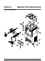
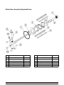
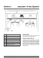
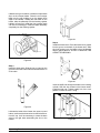
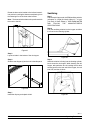
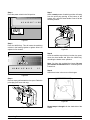
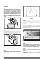
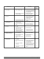
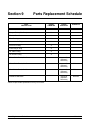
1
Model 632
Combo Freezer
Original Operating Instructions
030049--M
3/00 (Original Publication)
(Updated 8/10/12)
Complete this page for quick reference when service is required:
Taylor Distributor:
Address:
Phone:
Service:
Parts:
Date of Installation:
Information found on the data label:
Model Number:
Serial Number:
Electrical Specs:
Voltage
Cycle
Phase
Maximum Fuse Size:
Amps
Minimum Wire Ampacity:
Amps
Part Number:
E March, 2000 Taylor
All rights reserved.
030049-M
The word Taylor and the Crown design
are registered trademarks in the United States
of America and certain other countries.
Taylor Company
750 N. Blackhawk Blvd.
Rockton, IL 61072
Table of Contents
To the Installer . . . . . . . . . . . . . . . . . . . . . . . . . . . . . . . . . . . . . . . . . . . .
1
Installer Safety . . . . . . . . . . . . . . . . . . . . . . . . . . . . . . . . . . . . . . . . . . . . . . . . . . . . . . . .
1
Site Preparation . . . . . . . . . . . . . . . . . . . . . . . . . . . . . . . . . . . . . . . . . . . . . . . . . . . . . . .
1
Air Cooled Units . . . . . . . . . . . . . . . . . . . . . . . . . . . . . . . . . . . . . . . . . . . . . . . . . . . . . . .
2
Water Connections (Water Cooled Units Only) . . . . . . . . . . . . . . . . . . . . . . . . . . . .
2
Electrical Connections . . . . . . . . . . . . . . . . . . . . . . . . . . . . . . . . . . . . . . . . . . . . . . . . .
2
Beater Rotation . . . . . . . . . . . . . . . . . . . . . . . . . . . . . . . . . . . . . . . . . . . . . . . . . . . . . . .
3
Refrigerant . . . . . . . . . . . . . . . . . . . . . . . . . . . . . . . . . . . . . . . . . . . . . . . . . . . . . . . . . . .
3
To the Operator . . . . . . . . . . . . . . . . . . . . . . . . . . . . . . . . . . . . . . . . . . .
4
Compressor Warranty Disclaimer . . . . . . . . . . . . . . . . . . . . . . . . . . . . . . . . . . . . . . .
4
Section 3
Safety . . . . . . . . . . . . . . . . . . . . . . . . . . . . . . . . . . . . . . . . . . . . . . . . . . . .
5
Section 4
Operator Parts Identification . . . . . . . . . . . . . . . . . . . . . . . . . . . . . . .
7
Model 632 Exploded View . . . . . . . . . . . . . . . . . . . . . . . . . . . . . . . . . . . . . . . . . . . . . .
7
Soft Serve Door Assembly Exploded View . . . . . . . . . . . . . . . . . . . . . . . . . . . . . . . .
9
Shake Door Assembly Exploded View . . . . . . . . . . . . . . . . . . . . . . . . . . . . . . . . . . .
10
Accessories . . . . . . . . . . . . . . . . . . . . . . . . . . . . . . . . . . . . . . . . . . . . . . . . . . . . . . . . . .
11
Important: To the Operator . . . . . . . . . . . . . . . . . . . . . . . . . . . . . . . . .
12
Power Switch . . . . . . . . . . . . . . . . . . . . . . . . . . . . . . . . . . . . . . . . . . . . . . . . . . . . . . . . .
12
Indicator Light -- Mix low . . . . . . . . . . . . . . . . . . . . . . . . . . . . . . . . . . . . . . . . . . . . . . .
12
Mix Ref . . . . . . . . . . . . . . . . . . . . . . . . . . . . . . . . . . . . . . . . . . . . . . . . . . . . . . . . . . . . . .
13
Standby . . . . . . . . . . . . . . . . . . . . . . . . . . . . . . . . . . . . . . . . . . . . . . . . . . . . . . . . . . . . . .
13
Wash . . . . . . . . . . . . . . . . . . . . . . . . . . . . . . . . . . . . . . . . . . . . . . . . . . . . . . . . . . . . . . . .
13
Auto . . . . . . . . . . . . . . . . . . . . . . . . . . . . . . . . . . . . . . . . . . . . . . . . . . . . . . . . . . . . . . . . .
13
Thermistor Control . . . . . . . . . . . . . . . . . . . . . . . . . . . . . . . . . . . . . . . . . . . . . . . . . . . .
13
Reset Button . . . . . . . . . . . . . . . . . . . . . . . . . . . . . . . . . . . . . . . . . . . . . . . . . . . . . . . . .
13
Air Tube (Soft Serve) . . . . . . . . . . . . . . . . . . . . . . . . . . . . . . . . . . . . . . . . . . . . . . . . . .
14
Air Tube (Shake) . . . . . . . . . . . . . . . . . . . . . . . . . . . . . . . . . . . . . . . . . . . . . . . . . . . . . .
14
Adjustable Draw Handle (Soft Serve Only) . . . . . . . . . . . . . . . . . . . . . . . . . . . . . . . .
14
Section 1
Section 2
Section 5
Model 632
Table of Contents
Table of Contents -- Page 2
Operating Procedures . . . . . . . . . . . . . . . . . . . . . . . . . . . . . . . . . . . . .
15
Prior To Set--Up For Units With A Syrup Rail (Optional Feature) . . . . . . . . . . . . .
15
Freezing Cylinder Assembly -- Soft Serve Side . . . . . . . . . . . . . . . . . . . . . . . . . . . .
15
Freezing Cylinder Assembly -- Shake Side . . . . . . . . . . . . . . . . . . . . . . . . . . . . . . . .
19
Sanitizing . . . . . . . . . . . . . . . . . . . . . . . . . . . . . . . . . . . . . . . . . . . . . . . . . . . . . . . . . . . .
21
Priming . . . . . . . . . . . . . . . . . . . . . . . . . . . . . . . . . . . . . . . . . . . . . . . . . . . . . . . . . . . . . .
23
Closing Procedure . . . . . . . . . . . . . . . . . . . . . . . . . . . . . . . . . . . . . . . . . . . . . . . . . . . .
24
Draining Product From The Freezing Cylinder . . . . . . . . . . . . . . . . . . . . . . . . . . . .
24
Rinsing . . . . . . . . . . . . . . . . . . . . . . . . . . . . . . . . . . . . . . . . . . . . . . . . . . . . . . . . . . . . . .
24
Cleaning . . . . . . . . . . . . . . . . . . . . . . . . . . . . . . . . . . . . . . . . . . . . . . . . . . . . . . . . . . . . .
24
Disassembly . . . . . . . . . . . . . . . . . . . . . . . . . . . . . . . . . . . . . . . . . . . . . . . . . . . . . . . . . .
25
Brush Cleaning . . . . . . . . . . . . . . . . . . . . . . . . . . . . . . . . . . . . . . . . . . . . . . . . . . . . . . .
25
Important: Operator Checklist . . . . . . . . . . . . . . . . . . . . . . . . . . . . . .
26
During Cleaning and Sanitizing . . . . . . . . . . . . . . . . . . . . . . . . . . . . . . . . . . . . . . . . .
26
Troubleshooting Bacterial Count . . . . . . . . . . . . . . . . . . . . . . . . . . . . . . . . . . . . . . . .
26
Regular Maintenance Checks . . . . . . . . . . . . . . . . . . . . . . . . . . . . . . . . . . . . . . . . . . .
26
Winter Storage . . . . . . . . . . . . . . . . . . . . . . . . . . . . . . . . . . . . . . . . . . . . . . . . . . . . . . . .
27
Section 8
Troubleshooting Guide . . . . . . . . . . . . . . . . . . . . . . . . . . . . . . . . . . . .
28
Section 9
Parts Replacement Schedule . . . . . . . . . . . . . . . . . . . . . . . . . . . . . . .
30
Section 10
Parts List . . . . . . . . . . . . . . . . . . . . . . . . . . . . . . . . . . . . . . . . . . . . . . . . .
31
Wiring Diagrams . . . . . . . . . . . . . . . . . . . . . . . . . . . . . . . . . . . . . . . . . . . . . . . . . . . . . .
42
Section 6
Section 7
Note: Continuing research results in steady improvements; therefore, information
in this manual is subject to change without notice.
Note: Only instructions originating from the factory or its authorized translation
representative(s) are considered to be the original set of instructions.
E March, 2000 Taylor (Original Publication)
(Updated August, 2012)
All rights reserved.
030049-M
The word Taylor and the Crown design
are registered trademarks in the United States
of America and certain other countries.
Table of Contents
Taylor Company
750 N. Blackhawk Blvd.
Rockton, IL 61072
Model 632
Section 1
To the Installer
The following are general installation instructions. For
complete installation details, please see the checkout
card.
This unit has many sharp edges that can
cause severe injuries.
Note: Only instructions originating from the factory or
its authorized translation representative(s) are
considered to be the original set of instructions.
Installer Safety
Site Preparation
In all areas of the world, equipment should be
installed in accordance with existing local codes.
Please contact your local authorities if you have any
questions.
Review the area where the unit will be installed before
uncrating the unit. Make sure all possible hazards to
the user or the equipment have been addressed.
Care should be taken to ensure that all basic safety
practices are followed during the installation and
servicing activities related to the installation and
service of Taylor equipment.
S
S
S
S
For Indoor Use Only: This unit is designed to operate
indoors, under normal ambient temperatures of
70_-75_F (21_-24_C). The freezer has successfully
performed in high ambient temperatures of
104_(40_C) at reduced capacities.
Only authorized Taylor service personnel
should perform installation and repairs on
the equipment.
Authorized service personnel should consult
OSHA Standard 29CFRI910.147 or the
applicable code of the local area for the
industry standards on lockout/tagout
procedures before beginning any installation
or repairs.
Authorized service personnel must ensure
that the proper PPE is available and worn
when required during installation and
service.
Authorized service personnel must remove
all metal jewelry, rings, and watches before
working on electrical equipment.
This unit must NOT be installed in an area
where a water jet or hose can be used. NEVER use a
water jet or hose to rinse or clean the unit. Failure to
follow this instruction may result in electrocution.
This unit must be installed on a level surface
to avoid the hazard of tipping. Extreme care should be
taken in moving this equipment for any reason. Two or
more persons are required to safely move this unit.
Failure to comply may result in personal injury or
equipment damage.
The main power supply(s) to the freezer must
be disconnected prior to performing any repairs.
Failure to follow this instruction may result in personal
injury or death from electrical shock or hazardous
moving parts as well as poor performance or damage
to the equipment.
Uncrate the unit and inspect it for damage. Report any
damage to your Taylor Distributor.
This piece of equipment is made in the USA and has
USA sizes of hardware. All metric conversions are
approximate and vary in size.
Note: All repairs must be performed by an
authorized Taylor Service Technician.
110421
Model 632
1
To the Installer
Air Cooled Units
Electrical Connections
DO NOT obstruct air intake and discharge openings:
In the United States, this equipment is intended to be
installed in accordance with the National Electrical
Code (NEC), ANSI/NFPA 70-1987. The purpose of the
NEC code is the practical safeguarding of persons and
property from hazards arising from the use of
electricity. This code contains provisions considered
necessary for safety. In all other areas of the world,
equipment should be installed in accordance with the
existing local codes. Please contact your local
authorities.
Air cooled units require a minimum of 3” (76 mm) of
clearance around all sides of the freezer to allow for
adequate air flow across the condensers. A deflector
is provided to prevent recirculation of warm air. Failure
to allow adequate clearance can reduce the
refrigeration capacity of the freezer and possibly
cause permanent damage to the compressor.
Water Connections
FOLLOW YOUR LOCAL ELECTRICAL CODES!
(Water Cooled Units Only)
An adequate cold water supply must be provided with
a hand shut--off valve. On the underside rear of the
base pan, two 1/2” I.P.S. water connections for inlet
and outlet have been provided for easy hook--up. 1/2”
inside diameter water lines should be connected to the
machine. (Flexible lines are recommended, if local
codes permit.) Depending on local water conditions, it
may be advisable to install a water strainer to prevent
foreign substances from clogging the automatic water
valve. There will be only one water “in” and one water
“out” connection for both single--head and
double--head units. DO NOT install a hand shut--off
valve on the water “out” line! Water should always flow
in this order: first, through the automatic water valve;
second, through the condenser; and third, through the
outlet fitting to an open trap drain.
Each unit requires one power supply for each data
label on the unit. Check the data label(s) on the freezer
for branch circuit overcurrent protection or fuse, circuit
ampacity and other electrical specifications. Refer to
the wiring diagram provided inside of the electrical box,
for proper power connections.
CAUTION: THIS EQUIPMENT MUST BE
PROPERLY GROUNDED! FAILURE TO DO SO
CAN RESULT IN SEVERE PERSONAL INJURY
FROM ELECTRICAL SHOCK!
This unit is provided with an equipotential
grounding lug that is to be properly attached to the rear
of the frame by the authorized installer. The installation
location is marked by the equipotential bonding
symbol (5021 of IEC 60417-1) on both the removable
panel and the equipment’s frame.
A back flow prevention device is required
on the incoming water connection side. Please
refer to the applicable National, State, and local codes
for determining the proper configuration.
110407
To the Installer
2
Model 632
Refrigerant
S
S
S
Stationary appliances which are not
equipped with a power cord and a plug or
another device to disconnect the appliance
from the power source must have an all-pole
disconnecting device with a contact gap of
at least 3 mm installed in the external
installation.
Appliances that are permanently connected
to fixed wiring and for which leakage
currents may exceed 10 mA, particularly
when disconnected, not used for long
periods, or during initial installation, shall
have protective devices such as a GFI to
protect against the leakage of current,
installed by authorized personnel to the local
codes.
Supply cords used with this unit shall be
oil-resistant, sheathed flexible cable not
lighter than ordinary polychloroprene or
other equivalent synthetic
elastomer-sheathed cord (Code designation
60245 IEC 57) installed with the proper cord
anchorage to relieve conductors from strain,
including twisting, at the terminals and
protect the insulation of the conductors from
abrasion.
In consideration of our environment, Taylor
proudly uses only earth friendly HFC refrigerants. The
HFC refrigerant used in this unit is R404A. This
refrigerant is generally considered non-toxic and
non-flammable, with an Ozone Depleting Potential
(ODP) of zero (0).
However, any gas under pressure is potentially
hazardous and must be handled with caution. NEVER
fill any refrigerant cylinder completely with liquid.
Filling the cylinder to approximately 80% will allow for
normal expansion.
Use only R134a refrigerant that conforms to
the AHI standard 700 specification. The use of any
other refrigerant may expose users and operators to
unexpected safety hazards.
Refrigerant liquid sprayed onto the skin may
cause serious damage to tissue. Keep eyes and skin
protected. If refrigerant burns should occur, flush
immediately with cold water. If burns are severe, apply
ice packs and contact a physician immediately.
Beater Rotation
Beater rotation must be clockwise as viewed
looking into the freezing cylinder.
Taylor reminds technicians to be cautious of
government laws regarding refrigerant recovery,
recycling, and reclaiming systems. If you have any
questions regarding these laws, please contact the
factory Service Department.
Note: The following procedures must be
performed by an authorized Taylor service
technician.
To correct the rotation on a three--phase unit,
interchange any two incoming power supply lines at
freezer main terminal block only.
To correct rotation on a single--phase unit, change the
leads inside the beater motor. (Follow the diagram
printed on the motor.)
WARNING: R404A refrigerant used in
conjunction with polyolester oils is extremely moisture
absorbent. When opening a refrigeration system, the
maximum time the system is open must not exceed 15
minutes. Cap all open tubing to prevent humid air or
water from being absorbed by the oil.
Electrical connections are made directly to the
terminal block provided in the main control box located
behind the service panel.
120810
Model 632
3
To the Installer
Section 2
To the Operator
The freezer you have purchased has been carefully
engineered and manufactured to give you dependable
operation. The Taylor Model 632, when properly
operated and cared for, will produce a consistent
quality product. Like all mechanical products, this
machine will require cleaning and maintenance. A
minimum amount of care and attention is necessary if
the operating procedures outlined in this manual are
followed closely.
The user is responsible for returning the product to the
appropriate collection facility, as specified by your local
code.
For additional information regarding applicable local
laws, please contact the municipal facility and/or local
distributor.
This Operator’s Manual should be read before
operating or performing any maintenance on your
equipment.
Compressor Warranty Disclaimer
The refrigeration compressor(s) on this machine are
warranted for the term indicated on the warranty card
accompanying this machine. However, due to the
Montreal Protocol and the U.S. Clean Air Act
Amendments of 1990, many new refrigerants are
being tested and developed, thus seeking their way
into the service industry. Some of these new
refrigerants are being advertised as drop--in
replacements for numerous applications. It should be
noted that, in the event of ordinary service to this
machine’s refrigeration system, only the refrigerant
specified on the affixed data label should be used.
The unauthorized use of alternate refrigerants will void
your compressor warranty. It will be the owner’s
responsibility to make this fact known to any technician
he employs.
Your Taylor freezer will NOT eventually compensate
for and correct any errors during the set--up or filling
operations. Thus, the initial assembly and priming
procedures are of extreme importance. It is strongly
recommended that personnel responsible for the
equipment’s operation, both assembly and
disassembly, go through these procedures together in
order to be properly trained and to make sure that no
confusion exists.
In the event you should require technical assistance,
please contact your local authorized Taylor Distributor.
Note: Warranty is valid only if the parts are authorized
Taylor parts, purchased from an authorized Taylor
Distributor, and the required service work is provided
by an authorized Taylor service technician. Taylor
reserves the right to deny warranty claims on
equipment or parts if non--approved parts or
refrigerant were installed in the machine, system
modifications were performed beyond factory
recommendations, or it is determined that the failure
was caused by neglect or abuse.
Note: Constant research results in steady
improvements; therefore, information in this
manual is subject to change without notice.
It should also be noted that Taylor does not warrant the
refrigerant used in its equipment. For example, if the
refrigerant is lost during the course of ordinary service
to this machine, Taylor has no obligation to either
supply or provide its replacement either at billable or
unbillable terms. Taylor does have the obligation to
recommend a suitable replacement if the original
refrigerant is banned, obsoleted, or no longer available
during the five year warranty of the compressor.
If the crossed out wheeled bin symbol is
affixed to this product, it signifies that this product is
compliant with the EU Directive as well as other similar
legislation in effect after August 13, 2005. Therefore,
it must be collected separately after its use is
completed, and cannot be disposed as unsorted
municipal waste.
Taylor will continue to monitor the industry and test
new alternates as they are being developed. Should a
new alternate prove, through our testing, that it would
be accepted as a drop--in replacement, then the above
disclaimer would become null and void. To find out the
current status of an alternate refrigerant as it relates to
your compressor warranty, call the local Taylor
Distributor or the Taylor Factory. Be prepared to
provide the Model/Serial Number of the unit in
question.
081117
To the Operator
4
Model 632
Section 3
Safety
We, at Taylor Company, are concerned about the
safety of the operator when he or she comes in contact
with the freezer and its parts. Taylor has gone to
extreme efforts to design and manufacture built--in
safety features to protect both you and the service
technician. As an example, warning labels have been
attached to the freezer to further point out safety
precautions to the operator.
S
DO NOT operate the freezer unless it is
properly grounded.
S
DO NOT operate the freezer with larger
fuses than specified on the freezer data
label.
S
All repairs must be performed by an
authorized Taylor service technician. The
main power supplies to the machine must
be disconnected prior to performing any
repairs.
S
Cord Connected Units: Only Taylor
authorized service technicians may install a
plug on this unit.
S
Stationary appliances which are not
equipped with a power cord and a plug or
another device to disconnect the appliance
from the power source must have an all-pole
disconnecting device with a contact gap of
at least 3 mm installed in the external
installation.
S
Appliances that are permanently connected
to fixed wiring and for which leakage
currents may exceed 10 mA, particularly
when disconnected, not used for long
periods, or during initial installation, shall
have protective devices such as a GFI to
protect against the leakage of current,
installed by authorized personnel to the local
codes.
S
This unit is provided with an equipotential
grounding lug that is to be properly attached to the rear
of the frame by the authorized installer. The installation
location is marked by the equipotential bonding
symbol (5021 of IEC 60417-1) on both the removable
panel and the equipment’s frame.
Supply cords used with this unit shall be
oil-resistant, sheathed flexible cable not
lighter than ordinary polychloroprene or
other equivalent synthetic
elastomer-sheathed cord (Code designation
60245 IEC 57) installed with the proper cord
anchorage to relieve conductors from strain,
including twisting, at the terminals and
protect the insulation of the conductors from
abrasion.
DO NOT use a water jet to clean or rinse the
freezer. Failure to follow these instructions may result
in serious electrical shock.
Failure to follow these instructions may result in
electrocution. Contact your local authorized Taylor
Distributor for service.
IMPORTANT -- Failure to adhere to the
following safety precautions may result in severe
personal injury or death. Failure to comply with
these warnings may damage the machine and its
components. Component damage will result in
part replacement expense and service repair
expense.
DO NOT operate the freezer without reading
this Operator Manual. Failure to follow this instruction
may result in equipment damage, poor freezer
performance, health hazards, or personal injury.
Per IEC 60335--1 and its part 2 standards,
“This appliance is to be used only by trained personnel.
It is not intended for use by children or people with
reduced physical, sensory, or mental capabilities, or
lack of experience and knowledge, unless given
supervision or instruction concerning the use of the
appliance by a person responsible for their safety.”
110407
Model 632
5
Safety
This freezer must be placed on a level
surface. Failure to comply may result in personal injury
or equipment damage.
DO NOT allow untrained personnel to
operate this machine.
S DO NOT operate the freezer unless all
service panels and access doors are
restrained with screws.
S DO NOT remove any internal operating
parts (examples: freezer door, beater,
scraper blades, etc.) unless all control
switches are in the OFF position.
Failure to follow these instructions may result in severe
personal injury to fingers or hands from hazardous
moving parts.
S
Cleaning and sanitizing schedules are
governed by your state or local regulatory agencies
and must be followed accordingly. Please refer to the
cleaning section of this manual for the proper
procedure to clean this unit.
DO NOT obstruct air intake and discharge openings:
The minimum required air space on all sides is 3”
(76 mm). A deflector is provided to prevent
recirculation of warm air. Failure to follow this
instruction may cause poor freezer performance and
damage to the machine.
This unit has many sharp edges that can
cause severe injuries.
S
S
S
DO NOT put objects or fingers in the door
spout. This may contaminate the product
and cause severe personal injury from blade
contact.
USE EXTREME CAUTION when removing
the beater asssembly. The scraper blades
are very sharp.
CAUTION--SHARP EDGES: Two people
are required to handle the cup/cone
dispenser. Protective gloves must be worn
and the mounting holes must NOT be used
to lift or hold the dispenser. Failure to follow
this instruction can result in personal injury
to fingers or equipment damage.
For Indoor Use Only: This unit is designed to operate
indoors, under normal ambient temperatures of 70_ 75_F (21_ - 24_C). The freezer has successfully
performed in high ambient temperatures of
104_(40_C) at reduced capacities.
NOISE LEVEL: Airborne noise emission does not
exceed 78 dB(A) when measured at a distance of 1.0
meter from the surface of the machine and at a height
of 1.6 meters from the floor.
081117
Safety
6
Model 632
Section 4
Operator Parts Identification
Model 632 Exploded View
111101
Model 632
7
Operator Parts Identification
Model 632 Parts Identification List
ITEM
DESCRIPTION
PART NO.
ITEM
DESCRIPTION
PART NO.
1
COVER-HOPPER
053809
11
SCREW-1/4-20X3/8 RHM-SS
011694
2
TUBE-FEED-SHAKE-5/16 HOLE
028967-7
12
TUBE A.-FEED-SS-5/32 HOLE
X29429-2
CASTER 4” SWV 5/8 STEM
W/BRAKE
034081
3
4
ORIFICE
022465-100
13
PANEL-SERVICE
024439
14
TRAY-DRIP 22-7/8L X 5-1/5W
014533
15
SHIELD-SPLASH
037041
16
PANEL-SIDE-LEFT
067578
17
BOLT-CARRIAGE 1/4-20X3/4 SS
012347
18
STUD-NOSE CONE
022822
19
KNOB-DRAW VALVE
013635
20
PAN-DRIP 11-5/8 LONG
027503
5
O-RING-3/8 OD X .070 WIDE
016137
6
O-RING-.643 OD X .077 WIDE
018572
7
PANEL-REAR
053782
8
PANEL-SIDE-RIGHT
067577
9
ADAPTOR A.-CASTER
X18915
CASTER-SWV 5/8 STEM 4 IN
WHEEL
018794
10
111101
Operator Parts Identification
8
Model 632
Soft Serve Door Assembly Exploded View
Item
Description
Part No.
Item
Description
Part No.
1
Seal--Drive Shaft
032560
9b
Screw--Adjustment
033662
2
Shaft--Beater
032564
9c
O--Ring (Adjustment Screw)
015872
3
Beater A.--3.4 Qt. 1 Pin
X31761
10
O--Ring 5/16 OD x .070 W
016272
4
O--Ring--3/8 OD x .070 W
016137
11
Pin A.--Pivot
X22820
5
Blade--Scraper--Plastic
035174
12
Nut--Stud
021508
6
Bearing--Front
050216
13
Valve A.--Draw
X18303
7
Gasket--Door HT 4” Double
048926
14
O--Ring 7/8 OD x .103 W
014402
8
Door A.--1 Spout
X51531--10
15
Cap--Design 1.010” ID -- 6 Point
014218
9
Handle A.--Draw--Adj.
X26996
16
Plug--Prime
028805
9a
Draw Handle
044197
Model 632
9
Operator Parts Identification
Shake Door Assembly Exploded View
Item
Description
Part No.
Item
Part No.
1
Seal--Drive Shaft
032560
Gasket--Door
016672
2
Shaft--Beater
032790
8
Door Assembly
X30272--SER
3
Beater A.--7 Qt.--1 Pin
X46233
9
Valve A.--Draw
X13624--SP
4
Clip--Scraper Blade -- 8.75”
046238
10
O--Ring -- 1--1/16 OD
020571
5
Blade--Scraper--Plastic
046237
11
Decal--Lift Plate Front
015200
6
Bearing--Front
013116
12
Nut--Stud -- General Usage
021508
Operator Parts Identification
7
Description
10
Model 632
Accessories
Item
Description
Part No.
1
Brush--Rear Bearing
013071
2
Brush--Double Ended
013072
3
Brush--Draw Valve
014753
4
Brush--Mix Hopper
023316
5
Lubricant--Taylor 4 oz.
047518
6
Pail--Mix 10 qt.
013163
7
Sanitizer -- Kay 5 (125 Packets)
041082
Model 632
11
Operator Parts Identification
Section 5
Item
Important: To the Operator
Power Switch
Description
1
Power Switch
2
Mix Low Indicator Light
3
Mix (Hopper Refrigeration)
4
Standby
5
Wash
6
Auto
7
Thermistor Control
8
Adjustable Draw Handle
9
Reset Button
Important: To the Operator
When placed in the ON position, the power switch
allows SOFTECH control panel operation.
Indicator Light -- Mix low
Located on the front of the machine is a mix level
indicating light. When the light is flashing, it indicates
that the mix hopper has a low supply of mix and should
be refilled as soon as possible. Always maintain at
least 3” (76 mm) of mix in the hopper. If you neglect to
add mix, a freeze--up may occur. This will cause
eventual damage to the beater, blades, drive shaft,
and freezer door.
12
Model 632
Mix Ref
Wash
When the WASH key is pressed, the light comes on.
This indicates beater motor operation. The STANDBY
or AUTO modes must be cancelled first to activate the
WASH mode.
When the MIX REF key is pressed, the light comes on
indicating the mix hopper refrigeration system is
operating. MIX REF is controlled by the left side of the
freezer as viewed from the operator end. The MIX REF
function cannot be cancelled unless the AUTO or
STANDBY modes are cancelled first.
Auto
When the AUTO key is pressed, the light comes on.
This indicates that the main refrigeration system has
been activated. In the AUTO mode, the WASH or
STANDBY functions are automatically cancelled. The
MIX REF function is automatically locked in to
maintain the mix in the mix hopper.
Note: An indicating light and an audible tone will
sound whenever a mode of operation has been
pressed. To cancel any function, press the key again.
The light and mode of operation will shut off.
Standby
The Separate Hopper Refrigeration System (SHR)
and the Cylinder Temperature Retention System
(CTR) are standard features. The SHR incorporates
the use of a separate small refrigeration system to
maintain the mix in the hopper below 40_(4.4_C) to
assure bacteria control. The CTR works with the SHR
to maintain a good quality product. During long “No
Sale” periods, it is necessary to warm the product in
the freezing cylinder to approximately 35_F to 40_F
(1.7_C to 4.4_C) to prevent overbeating and product
breakdown.
Thermistor Control
The thermistor control is used to vary the “cycle off”
temperature for the shake side of the machine. The
serving temperature of the shake can be adjusted
colder by turning the knob to the right. To achieve a
warmer temperature, turn the knob to the left.
Reset Button
To activate the SHR and CTR, press the STANDBY
key. Remove the air orifice and place the air tube (end
without the hole) into the mix inlet hole.
The reset button is located in the service panel. The
reset protects the beater motor from an overload
condition. If an overload occurs, the reset mechanism
will trip. To properly reset the freezer, press the AUTO
key to cancel the cycle. Turn the power switch to the
OFF position. Press the reset button firmly.
When the STANDBY key is pressed, the light comes
on, indicating the CTR (Cylinder Temperature
Retention System) has been activated. In the
STANDBY mode, the WASH and AUTO functions are
automatically cancelled. The MIX REF function is
automatically locked in to maintain the mix in the
hopper.
Note: Do not use metal objects to press
the reset button. Failure to follow this instruction
may result in electrocution.
Turn the power switch to the ON position. Press the
WASH key and observe the freezer’s performance.
Open the side access panel. Make sure the beater
motor is turning the drive shaft in a clockwise direction
(from the operator end) without binding.
To resume normal operation, press the AUTO key.
When the unit cycles off, the product in the freezing
cylinder will be at serving viscosity. At this time, place
the air tube (end with the hole) into the mix inlet hole
and install the air orifice.
Model 632
If the beater motor is turning properly, press the WASH
key to cancel the cycle. Press the AUTO key to resume
normal operation.
13
Important: To the Operator
Air Tube (Soft Serve)
Air Tube (Shake)
The air tube serves two purposes. One end of the tube
has a hole and the other end does not.
After priming the machine, install the air tube. Install
the air tube in the position that will allow for the hole
marked “1” to be in the down position. This is the AUTO
position, and will allow mix and air to travel to the
freezing cylinder while product is being dispensed.
Figure 2
During long “No Sale” periods, reverse the position of
the air tube. Position the air tube to allow the hole
marked “2” to be in the down position. This is the
STANDBY position, and will prevent any mix from
entering the freezing cylinder.
Figure 1
1.
2.
After priming the machine, lubricate the o--rings
on the air tube (the end with the hole) and
place it into the mix inlet hole. Every time the
draw handle is raised, new mix and air from the
hopper will flow down into the freezing cylinder.
This will keep the freezing cylinder properly
loaded and will maintain overrun.
Note: Be sure to place the air tubes in the correct
position when returning the freezer to the AUTO
position.
Adjustable Draw Handle
(Soft Serve Only)
During long “No Sale” periods, remove the air
orifice. Lubricate the o--rings on the air tube
(the end without the hole), and place it into
the mix inlet hole. This will prevent any mix
from entering the freezing cylinder.
These units feature an adjustable draw handle to
provide the best portion control. The draw handle
should be adjusted to provide a flow rate of 5 to 7--1/2
oz. of product per 10 seconds. To INCREASE the flow
rate, turn the screw COUNTERCLOCKWISE. Turn
the screw CLOCKWISE to DECREASE the flow rate.
During Sanitizing and Rinsing, the flow rate can be
increased by removing the pivot pin and placing the
restrictive bar on the TOP. When drawing product,
always place the restrictive bar on the bottom.
The air orifice is used to meter a certain amount
of air into the freezing cylinder. The air orifice
maintains overrun and allows enough mix to enter
the freezing cylinder after a draw.
Important: To the Operator
14
Model 632
Section 6
Operating Procedures
Freezing Cylinder Assembly -- Soft
Serve Side
We begin our instructions at the point where we enter
the store in the morning and find the parts
disassembled and laid out to air dry from the previous
night’s cleaning.
These opening procedures will show you how to
assemble these parts into the freezer, sanitize them,
and prime the freezer with fresh mix in preparation to
serve your first portion.
If you are disassembling the machine for the first time
or need information to get to this starting point in our
instructions, turn to page 25, “Disassembly”, and start
there.
Note: When lubricating parts, use an approved food
grade lubricant (example: Taylor Lube).
MAKE SURE CONTROL SWITCH IS IN THE
“OFF” POSITION. Failure to do so may cause injury
from hazardous moving parts, or electrocution.
Step 1
Install the drive shaft. Lubricate the groove and shaft
portion that comes in contact with the bearing on the
beater drive shaft. Slide the seal over the shaft and
groove until it snaps into place. DO NOT lubricate the
hex end of the drive shaft. Fill the inside portion of the
seal with 1/4” more lubricant and lubricate the flat side
of the seal that fits onto the rear shell bearing.
Prior To Set--Up For Units With A
Syrup Rail (Optional Feature)
Step 1
Remove the two stainless syrup jars with topping
pumps from the syrup rail. Check the water level in the
heated syrup topping well. Make sure the water is filled
to the indicating mark on the bottom of the well.
Step 2
Place the heater switch in the ON position.
Note: This heating process will take approximately
2--1/2 hours to reach temperature. The water level in
the topping wells must be checked at least once daily.
Step 3
Prepare a pail of approved 100 PPM sanitizing solution
(examples: 2--1/2 gal. [9.5 liters] of Kay--5R or 2 gal.
[7.6 liters] of Stera--SheenR). USE WARM WATER
AND
FOLLOW
THE
MANUFACTURER’S
SPECIFICATIONS. Sanitize the topping pumps by
placing the entire pump assembly in the pail of sanitizing solution. Pump the solution through the assembly
to thoroughly sanitize the pump.
Figure 3
Step 4
Remove the two topping pumps. Fill each stainless
syrup jar with topping. Replace the topping pumps in
the syrup jars.
081117
Model 632
15
Operating Procedures
Insert the drive shaft into the freezing cylinder, hex end
first, and into the rear shell bearing until the seal fits
securely over the rear shell bearing. Engage the hex
end firmly into the drive coupling. Be sure the drive
shaft fits into the drive coupling without binding.
Figure 6
Slide the beater the remainder of the way into the
freezing cylinder and over the end of the drive shaft.
The beater should fit snugly, but not so tightly that the
beater cannot be turned slightly to engage the drive
shaft. If the beater slides in too easily with little or no
resistance, there will not be enough force against the
beater to hold the blades in place. If this is the case,
contact your authorized Taylor service agent.
Figure 4
Step 2
Take one of the scraper blades and slip it under the
hook at the front of the beater. Wrap the blade around
the beater following the helix and pushing the blade
down onto the helix as you wrap. At the back end of the
beater, slip the blade under the hook. Repeat this
step for the second scraper blade.
Step 3
Assemble the freezer door. Place the large rubber
gasket into the groove on the back side of the freezer
door.
Slide the white plastic front bearing over the baffle rod
onto the bearing hub making certain that the flanged
end of the bearing is resting against the freezer door.
DO NOT LUBRICATE THE GASKET OR THE
FRONT BEARING.
Figure 5
Holding the beater securely, slide the beater one third
of the way into the freezing cylinder. Looking into the
freezing cylinder, align the hole at the rear of the beater
with the flats on the end of the drive shaft.
Operating Procedures
Figure 7
16
Model 632
Slide the two o--rings into the grooves on the prime
plug. Apply an even coat of Taylor Lube to the o--rings
and shaft.
Step 5
Install the draw valve. Slide the two o--rings into the
grooves on the draw valve, and lubricate.
Figure 8
Figure 11
Insert the prime plug into the hole in the top of the
freezer door, and push down.
Lubricate the inside of the freezer door spout, top and
bottom, and insert the draw valve from the bottom
until the slot in the draw valve comes into view.
Figure 9
Step 4
Install the freezer door. Insert the baffle rod through the
opening in the beater and seat the door flush with the
freezing cylinder. With the door seated on the freezer
studs, install the handscrews. Tighten equally in a
crisscross pattern to insure the door is snug.
Step 6
Install the adjustable draw handle. Slide the o--ring into
the groove on the pivot pin, and lubricate.
Figure 10
Figure 13
Model 632
Figure 12
17
Operating Procedures
Slide the fork over the bar in the slot of the draw valve.
Secure with pivot pin.
Slide the small o--ring into the groove of the air orifice.
Do not lubricate the o--ring.
Figure 14
Note: These units feature adjustable draw handles to
provide the best portion control. The draw handles can
be adjusted for different flow rates. See page 14 for
more information on adjusting these handles.
Figure 17
Step 7
Snap the design cap over the end of the door spout.
Note: Make sure the hole in the air orifice is clean and
is not clogged. If the hole in the air orifice should
become clogged, use soap and hot water to clear the
hole. Do not enlarge the hole in the air orifice.
Install the air orifice into the hole in the top of the air
tube (in the end without the small hole on the side).
Figure 15
Step 8
Slide two o--rings on one end of the air tube. Slide two
o--rings on the other end of the air tube.
Figure 18
Step 9
Lay the air tube (with the air orifice installed) in the
bottom of the mix hopper for sanitizing.
Note: The air tube for the shake side does not require
o--rings or an air orifice.
Figure 16
Operating Procedures
18
Model 632
Insert the drive shaft into the freezing cylinder, hex end
first, and into the rear shell bearing until the seal fits
securely over the rear shell bearing. Engage the hex
end firmly into the drive coupling. Be sure the drive
shaft fits into the drive coupling without binding.
Freezing Cylinder Assembly -Shake Side
Note: When lubricating parts, use an approved food
grade lubricant (example: Taylor Lube).
MAKE SURE CONTROL SWITCH IS IN THE
“OFF” POSITION. Failure to do so may cause injury
from hazardous moving parts, or electrocution.
Step 1
Install the drive shaft. Lubricate the groove and shaft
portion that comes in contact with the bearing on the
beater drive shaft. Slide the seal over the shaft and
groove until it snaps into place. DO NOT lubricate the
hex end of the drive shaft. Fill the inside portion of the
seal with 1/4” more lubricant and lubricate the flat side
of the seal that fits onto the rear shell bearing.
Figure 20
Step 2
Install the beater assembly. First check the scraper
blades for any nicks or signs of wear. If any nicks are
present, replace the blade(s).
Figure 21
Note: To prevent costly damage, the hole on the
scraper blade must fit securely over the pin.
Figure 19
Model 632
19
Operating Procedures
If blades are in good condition, install the scraper blade
clips on the scraper blades. Place the rear scraper
blade over the rear holding pin on the beater (knife
edge to the outside). Holding the rear blade on the
beater, slide the assembly into the freezing cylinder
halfway, tail end first. Install the front scraper blade
over the front holding pin. Slide the beater assembly
completely into the freezing cylinder.
Figure 24
Step 4
Install the freezer door. Place the freezer door gasket
into the groove on the back of the freezer door. Slide
the front bearing over the baffle rod so the flanged
edge is against the door. DO NOT LUBRICATE THE
GASKET OR BEARING.
Figure 22
Step 3
Install the draw valve. Slide the two o--rings into the
grooves on the draw valve and lubricate the bottom 1/2
of the valve.
Figure 25
Insert the baffle rod through the beater in the freezing
cylinder. With the door seated on the freezer studs,
install the stud nuts. Tighten equally in a criss--cross
pattern to insure the door is snug.
Figure 23
Lubricate the inside of the freezer door spout, top and
bottom, and insert the draw valve into the freezer door
from the top. It will be necessary to rotate the draw
valve to the right when assembling the door to the
freezer.
Operating Procedures
Figure 26
20
Model 632
Sanitizing
Rotate the draw valve bracket to the left and center it
into position by raising the draw arm and placing it into
the slotted groove of the draw valve bracket.
Step 1
Prepare a pail of approved 100 PPM sanitizing solution
(examples: 2--1/2 gal. [9.5 liters] of Kay--5R or 2 gal.
[7.6 liters] of Stera--SheenR). USE WARM WATER
AND
FOLLOW
THE
MANUFACTURER’S
SPECIFICATIONS.
Note: The draw valve bracket must be positioned with
the notch to the left.
Step 2
Pour the sanitizing solution into the hopper and allow
it to flow into the freezing cylinder.
Figure 27
Step 5
Lay the air tube in the bottom of the mix hopper.
Figure 29
Step 6
Slide the rear drip pan(s) into the hole in the side panel.
Step 3
While the solution is flowing into the freezing cylinder,
brush clean the mix hopper. While cleaning the mix
hopper, take particular care in brushing the mix level
sensing probe on the rear wall of the hopper, the mix
inlet hole, and the air tubes.
Figure 28
Step 7
Install the drip tray and splash shield.
Figure 30
081117
Model 632
21
Operating Procedures
Step 7
When a steady stream of sanitizing solution is flowing
from the prime plug opening in the bottom of the
freezer door, open the draw handle. Draw off all the
sanitizing solution.
Step 4
Place the power switch in the ON position.
Figure 31
Step 5
Press the WASH key. This will cause the sanitizing
solution in the freezing cylinder to agitate. Allow it to
agitate for five minutes.
Figure 34
Step 8
Once the sanitizer stops flowing from the door spout,
close the draw handle and press the WASH key,
cancelling the beater motor operation.
Note: You have just sanitized the freezer. Be sure
your hands are sanitized before continuing these
instructions.
Step 9
Stand the air tube in the corner of the hopper.
Figure 32
Step 6
Place an empty pail beneath the door spout. Raise the
prime plug (soft serve side only).
Figure 35
Repeat steps 1 through 9 for the shake side of the
freezer.
Figure 33
Operating Procedures
22
Model 632
Priming
Step 1
With a pail beneath the door spout, open the draw
handle. Be sure the prime plug is still in the UP position
(soft serve side only). Pour two gallons (7.6 liters) of
fresh mix into the mix hopper and allow it to flow into
the freezing cylinder. This will force out any remaining
sanitizing solution. When full strength mix is flowing
from the door spout, close the draw handle.
Note: Use only fresh mix when priming the freezing
cylinder.
Figure 38
Step 5
Press the AUTO key. The AUTO light will come on
indicating the main refrigeration system is operating.
When the unit cycles off, the product will be at serving
viscosity.
Note: The MIX REF light will come on, indicating the
mix refrigeration system is operating to maintain the
mix in the mix hopper.
Figure 36
Step 2
Once a steady stream of mix starts to flow from the
prime plug opening in the bottom of the freezer door,
push down the prime plug (soft serve only).
Figure 39
Step 6
Fill the hopper with mix. As the mix level comes in
contact with the mix level sensing probe on the rear
wall of the hopper, the MIX LOW light will shut off.
Figure 37
Step 3
Lubricate the o--rings on the air tube on the end with
the small hole on the side (soft serve only).
Step 7
Place the mix hopper cover in position over the mix
hopper.
Step 4
Install the air tube (the end with the hole) with the air
orifice installed into the mix inlet hole in the mix hopper
(soft serve only).
Model 632
Repeat steps 1 through 7 for the other side of the
freezer.
23
Operating Procedures
Closing Procedure
Rinsing
Step 1
Pour two gallons (7.6 liters) of cool clean water into the
mix hopper. With the brushes provided, scrub the mix
hopper, mix inlet hole and mix level sensing probe.
To disassemble your unit, the following items will be
needed:
S
S
S
S
S
Two cleaning pails
Sanitized stainless steel rerun can with lid
Step 2
With a pail beneath the door spout, (raise the prime
plug -- soft serve only) and press the WASH key.
Necessary brushes (provided with freezer)
Cleaner
Step 3
When a steady stream of rinse water is flowing from
the prime plug opening in the bottom of the freezer
door (soft serve only), open the draw handle. Drain all
the rinse water from the freezing cylinder, close the
draw handle and press the WASH key cancelling the
WASH mode.
Single service towels
Draining Product From The
Freezing Cylinder
Repeat steps 1 through 3 for the shake side of the
freezer.
Step 1
Press the AUTO key, cancelling compressor and
beater motor operation.
Cleaning
Step 1
Prepare a pail of approved 100 PPM cleaning solution
(examples: 2--1/2 gal. [9.5 liters] of Kay--5R or 2 gal.
[7.6 liters] of Stera--SheenR). USE WARM WATER
AND
FOLLOW
THE
MANUFACTURER’S
SPECIFICATIONS.
Press the MIX REF key, cancelling the mix hopper
refrigeration system.
Step 2
Remove the hopper cover, hopper gasket and air tube.
Take these parts to the sink for cleaning.
Step 2
Push down the prime plug (soft serve only). Pour the
cleaning solution into the mix hopper.
Step 3
If local health codes permit the use of rerun, place
a sanitized, NSF approved stainless steel rerun
container beneath the door spout. Press the WASH
key and open the draw handle. Drain the remaining
product from the freezing cylinder and mix hopper.
When the flow of product stops, press the WASH key
and close the draw handle. Place the sanitized lid on
the rerun container and place it in the walk--in cooler.
(See page 5 for instructions regarding the proper use
of rerun.)
Step 3
While the solution is flowing into the freezing cylinder,
brush clean the mix hopper, mix level sensing probe,
and the mix inlet hole.
Step 4
Press the WASH key. This will cause the cleaning
solution in the freezing cylinder to agitate.
Step 5
Place an empty pail beneath the door spout and raise
the prime plug (soft serve only).
Note: If local health codes DO NOT permit the use
of rerun, the product must be discarded. Follow the
instructions in the previous step, except drain the
product into a mix pail and properly discard the mix.
Step 6
When a steady stream of cleaning solution is flowing
from the prime plug opening in the bottom of the
freezer door (soft serve only), open the draw handle.
Draw off all of the solution.
Repeat steps 1 through 3 for the other side of the
freezer.
Step 7
Once the cleaner stops flowing from the door spout,
close the draw handle and press the WASH key
cancelling the WASH mode.
ALWAYS FOLLOW LOCAL HEALTH CODES.
081117
Operating Procedures
24
Model 632
Note: To remove o--rings, use a single service towel
to grasp the o--ring. Apply pressure in an upward
direction until the o--ring pops out of its groove. With
the other hand, push the top of the o--ring forward and
it will roll out of the groove and can be easily removed.
If there is more than one o--ring to be removed, always
remove the rear o--ring first. This will allow the o--ring
to slide over the forward rings without falling into the
open grooves.
Repeat steps 1 through 7 for the other side of the
freezer.
Disassembly
BE SURE THE POWER SWITCH IS IN THE
OFF POSITION. MAKE SURE NO LIGHTS ARE LIT
ON THE CONTROL PANEL.
Step 4
Remove the o--rings from the air tube and air orifice
(soft serve only).
Step 1
Remove the stud nuts, freezer door(s), beater(s),
scraper blades, and drive shaft(s) from the freezing
cylinder(s). Take these parts to the sink for cleaning.
Step 5
Return to the freezer with a small amount of cleaning
solution. Brush clean the rear shell bearing(s) at the
back of the freezing cylinder(s) with the black bristle
brush.
Step 2
Remove the front drip tray and the splash shield.
Brush Cleaning
Step 1
Prepare a sink with an approved cleaning solution
(examples: Kay--5R or Stera--SheenR). USE WARM
WATER AND FOLLOW THE MANUFACTURER’S
SPECIFICATIONS. If another approved cleaner is
used, dilute it according to the label instructions.
(IMPORTANT: Follow the label directions. Too
STRONG of a solution can cause parts damage, while
too MILD of a solution will not provide adequate
cleaning.) Make sure all brushes provided with the
freezer are available for brush cleaning.
Figure 40
Step 6
Remove the rear drip pan(s) and take to the sink for
cleaning.
Step 2
Remove the seal(s) from the drive shaft(s).
Note: If the drip pan is filled with an excessive amount
of mix, refer to the Troubleshooting Guide.
Step 3
From the freezer door(s) remove:
S
S
S
S
S
S
S
Step 7
Thoroughly brush clean all disassembled parts in the
cleaning solution making sure all lubricant and mix film
is removed. Take particular care to brush clean the
draw valve core(s) in the freezer door. Place all the
cleaned parts on a clean, dry surface to air dry
overnight.
gasket(s)
front bearing(s)
pivot pin(s)
adjustable draw handle(s)
design cap(s)
draw valve(s)
prime plug
Step 8
Wipe clean all exterior surfaces of the freezer.
Remove all o--rings.
081117
Model 632
25
Operating Procedures
Section 7
Important: Operator Checklist
During Cleaning and Sanitizing
prime the machine with rerun. When using
rerun, skim off the foam and discard. Mix the
rerun with fresh mix in a ratio of 50/50 during the
days operation.
ALWAYS FOLLOW LOCAL HEALTH CODES.
j 6. On a designated day of the week, run the mix as
low as feasible and discard it after closing. This
will break the rerun cycle and reduce the
possibility of high bacteria and coliform counts.
Cleaning and sanitizing schedules are governed
by federal, state, or local regulatory agencies,
and must be followed accordingly. If the unit
has a “Standby mode”, it must not be used in
lieu of proper cleaning and sanitizing
procedures and frequencies set forth by the
ruling health authority. The following check
points should be stressed during the cleaning
and sanitizing operations.
j 7. Properly prepare the cleaning and sanitizing
solutions. Read and follow label directions
carefully. Too strong of a solution may damage
the parts and too weak of a solution will not do
an adequate job of cleaning or sanitizing.
j 8. The temperature of the mix in the mix hopper
and walk--in cooler should be below 40_F.
(4.4_C.).
CLEANING AND SANITIZING MUST BE
PERFORMED DAILY.
Regular Maintenance Checks
Cleaning and sanitizing schedules are governed by
your State or local regulatory agencies and must be
followed accordingly. The following check points
should be stressed during the cleaning and sanitizing
operations.
j 1. Replace scraper blades that are nicked or
damaged. Before installing the beater
assembly, be certain that scraper blades are
properly attached to the helix or pins.
Troubleshooting Bacterial Count
j 2. Check the rear shell bearing for signs of wear
(excessive mix leakage in rear drip pan) and be
certain it is properly cleaned.
j 1. Thoroughly clean and sanitize machine
regularly, including complete disassembly and
brush cleaning.
j 3. Using a screwdriver and cloth towel, keep the
rear shell bearing and the female drive socket
clean and free of lubricant and mix deposits.
j 2. Use all brushes supplied for thorough cleaning.
The brushes are specially designed to reach all
mix passageways.
j 4. Dispose of o--rings and seals if they are worn,
torn, or fit too loosely, and replace with new
ones.
j 3. Use the white bristle brush to clean the mix inlet
hole which extends from the mix hopper down
to the rear of the freezing cylinder.
j 5. Follow all lubricating procedures as outlined in
“Assembly”.
j 6. If your machine is air cooled, check the
condensers for accumulation of dirt and lint.
Dirty condensers will reduce the efficiency and
capacity of the machine. Condensers should be
cleaned monthly with a soft brush. Never use
screwdrivers or other metal probes to clean
between the fins.
Note: For machines equipped with an air filter,
it will be necessary to vacuum clean the filters
on a monthly schedule.
j 4. Use the black bristle brush to thoroughly clean
the rear shell bearing located at the rear of the
freezing cylinder. Be sure to have a generous
amount of cleaning solution on the brush.
j 5. IF LOCAL HEALTH CODES PERMIT THE
USE OF RERUN, make sure the mix rerun is
stored in a sanitized, covered stainless steel
container and used the following day. DO NOT
081117
Important: Operator Checklist
26
Model 632
Winter Storage
CAUTION: Always disconnect
electrical power prior to cleaning the
condenser. Failure to follow this instruction
may result in electrocution.
If the place of business is to be closed during the winter
months, it is important to protect the freezer by
following certain precautions, particularly if the
building is subject to freezing conditions.
j 7. If your machine is equipped with an auxiliary
refrigeration system, check the auxiliary
condenser for accumulation of dirt and lint. Dirty
condensers will reduce the refrigeration
capacity of the mix hopper. Condensers must
be cleaned monthly with a soft brush. Never
use screwdrivers or other metal probes to clean
between the fins.
Disconnect the freezer from the main power source to
prevent possible electrical damage.
On water cooled freezers, disconnect the water
supply. Relieve pressure on the spring in the water
valve. Use air pressure on the outlet side to blow out
any water remaining in the condenser. This is
extremely important. Failure to follow this procedure
may cause severe and costly damage to the
refrigeration system.
CAUTION: Always disconnect
electrical power prior to cleaning the
condenser. Failure to follow this instruction
may result in electrocution.
Your local Taylor Distributor can perform this winter
storage service for you.
j 8. If your machine is water cooled, check the water
lines for kinks or leaks. Kinks can occur when
the machine is moved back and forth for
cleaning
or
maintenance
purposes.
Deteriorated or cracked water lines should be
replaced only by an authorized Taylor
distributor.
Wrap detachable parts of the freezer such as beater,
blades, drive shaft, and freezer door, and place them
in a protected dry place. Rubber trim parts and gaskets
can be protected by wrapping them with
moisture--proof paper. All parts should be thoroughly
cleaned of dried mix or lubrication which attract mice
and other vermin.
081117
Model 632
27
Important: Operator Checklist
Section 8
PROBLEM
1.
2.
3.
No product is being
dispensed with draw valve
open and the machine in the
AUTO mode.
The product is too stiff.
The product is too soft.
Troubleshooting Guide
PROBABLE CAUSE
REMEDY
PAGE
REF.
a. Freeze--up in mix inlet hole.
a. Call service technician to
adjust the mix hopper
temperature.
------
b. Beater motor out on reset.
b. Reset the freezer.
c. The beater is rotating
counterclockwise from the
operator end.
c. Contact service technician to
correct rotation to clockwise
from operator end.
------
d. The circuit breaker is off or
the fuse is blown.
d. Turn the breaker on, or
replace the fuse.
------
e. There is inadequate mix in
the mix hopper.
e. Fill the mix hopper with mix.
23
f. The air orifice is not installed
(soft serve only).
f. Install air orifice in air tube.
23
a. The viscosity needs
adjustment.
a. Contact service technician.
------
b. The air orifice is not installed
(soft serve only).
b. Install air orifice in air tube.
23
a. Viscosity needs adjustment.
a. Contact service technician.
------
b. Not enough air space around
unit. (Air cooled units)
b. Allow for adequate air flow
across the condenser.
c. Worn scraper blades.
c. Replace regularly.
30
d. Dirty condenser (A/C)
d. Clean monthly.
26
e. Mix is out of date.
e. Use only fresh mix.
f. Loss of water. (W/C)
f. Locate cause of water loss
and correct.
13
2
-----27
4.
The mix in the mix hopper is
too cold.
a. The temperature is out of
adjustment.
a. Call service technician to
adjust the mix hopper
temperature.
------
5.
The mix in the mix hopper is
too warm.
a. The temperature is out of
adjustment.
a. Call service technician to
adjust the mix hopper
temperature.
------
b. The mix hopper cover is not
in position.
b. Place the cover in position.
23
c. The MIX REF light is not lit.
c. Press the MIX REF key.
13
Troubleshooting Guide
28
Model 632
PROBLEM
6.
7.
8.
9.
The drive shaft is stuck in the
drive coupling.
The freezing cylinder walls
are scored.
Excessive mix leakage into
the rear drip pan.
Excessive mix leakage from
door spout.
10. No freezer operation after
pressing the AUTO key.
11. Product is not feeding into the
freezing cylinder.
Model 632
PROBABLE CAUSE
REMEDY
PAGE
REF.
a. Rounded corners of drive
shaft, coupling, or both.
a. Call service technician to
correct cause, and to replace
the necessary components.
Do not lubricate the hex end
of the drive shaft.
b. Mix and lubricant collected in
the drive coupling.
b. Brush clean the rear shell
bearing area regularly.
a. The beater assembly is bent.
a. Call service technician to
repair or replace the beater
and to correct the cause of
insufficient mix in the
freezing cylinder.
b. The front bearing is missing
or worn on the freezer door.
b. Install or replace the front
bearing.
16
a. Missing or worn drive shaft
seal on drive shaft.
a. Install or replace regularly.
15 / 30
b. The rear shell bearing is
worn.
b. Call service technician to
replace rear shell bearing.
a. Missing or worn draw valve
o--rings.
a. Install or replace regularly.
b. Inadequate lubrication of
draw valve o--rings.
b. Lubricate properly.
17
c. Wrong type of lubricant is
being used (example:
petroleum base lubricant).
c. Use the proper lubricant
(example: Taylor Lube).
15
a. Unit is unplugged.
a. Plug into wall receptacle.
------
b. The circuit breaker is off or
the fuse is blown.
b. Turn the breaker on, or
replace the fuse.
------
c. The beater motor is out on
reset.
c. Reset the freezer.
13
a. Inadequate level of mix in the
mix hopper.
a. Fill the mix hopper with mix.
23
b. The mix inlet hole is frozen
up.
b. The mix hopper temperature
needs adjustment. Call
service technician.
------
c. The air tube is installed
incorrectly.
c. Install the air tube in the mix
inlet hole, using the end with
the small hole in the side.
23
d. The air orifice is not installed
(soft serve).
d. Install the air orifice in the air
tube.
23
29
------
25
------
-----17 / 30
Troubleshooting Guide
Section 9
Parts Replacement Schedule
PART
DESCRIPTION
EVERY
3 MONTHS
EVERY
6 MONTHS
ANNUALLY
White Bristle Brush, 3” x 7”
Inspect &
Replace if
Necessary
Minimum
White Bristle Brush, 1” x 2”
Inspect &
Replace if
Necessary
Minimum
Black Bristle Brush, 1” x 2”
Inspect &
Replace if
Necessary
Minimum
Double--Ended Brush
Inspect &
Replace if
Necessary
Minimum
Drive Shaft Seal
X
*Scraper Blade (Soft Serve)
X
Freezer Door Gasket
X
Front Bearing
X
Draw Valve O--Ring
X
Pivot Pin O--Ring
X
Prime Plug O--Ring
X
Air Tube O--Ring
X
Air Orifice O--Ring
X
*Shake scraper blade replacement is every four months.
Parts Replacement Schedule
30
Model 632
Model 632
ADAPTOR A.-CASTER
BEARING-FRONT
BEARING-FRONT
BEARING-REAR SHELL *NICK.PLATE
+GUIDE-DRIP SEAL
+NUT-BRASS BEARING
+WASHER-BEARING LOCK
BEATER A.-3.4QT-HELICORE
+BLADE-SCRAPER-PLASTIC 17L
BEATER A.-7QT-1 PIN-SUPPORT
+BLADE-SCRAPER-PLASTIC 9-13/16L
+CLIP-SCRAPER BLADE*8.75 INCH*
BELT-AX39
BELT-AX41
BLOCK-TERMINAL 2P-L1,L2
BLOCK-TERMINAL 3P-L1,L2
BLOWER A.
BOOT-CAPACITOR INSULATING
CAPACITOR-RUN 7.5UF/370V
MOTOR-FAN 208-230V 50/60 HZ
BOARD-LOGIC-GEN 2.10-W/SEL DI
BOARD-POWER-GEN 1 & 2
BOARD-PWR/RLY-GEN 1&2 SHAKE
BOARD-POWER-GEN 1 & 2
BRUSH-DOUBLE ENDED-PUMP&FEED T
BRUSH-DRAW VALVE 1-1/2"OD X 3"
BRUSH-MIX PUMP BODY-3"X7"WHITE
BRUSH-REAR BRG 1IN.DX2IN.LGX14
CABLE-RIBBON-PWR/RELAY-60 IN
CAP-DESIGN-1.010"ID-6 POINT
CASTER-SWV 5/8 STEM 4IN WHEEL
DESCRIPTION
X18915
050216
013116
031324
028992
028991
012864
X31761
035174
X46233
046237
046238
023874
023876
039422
039423
X53725-27
031314
034749
053481-27
X36641SER2
X32326-SER
X34983-SER
X32326-SER
013072
014753
023316
013071
032445
014218
018794
PART
NUMBER
4
1
1
2
2
2
2
1
2
1
2
2
2
1
2
2
1
1
1
1
2
2
*
*
1
1
1
1
2
1
4
QTY.
103
000
000
000
000
000
000
103
000
103
000
103
000
000
103
103
103
000
103
103
212
212
212
212
000
000
000
000
103
000
103
WARR.
CLASS
31
LOGIC TO POWER BOARD
SOFT SERVE - J9037236/UP
REPLACES X36641SER1
S/N K9105773 & UP
SHAKE S/N K9105771 & PRIOR
SOFT SERVE S/N K9105771 & PRIOR
SOFT SERVE
SHAKE
208-240/60/1
208-240/60/3
SHAKE
SOFT SERVE
SOFT SERVE
SHAKE
REMARKS
PARTS
UPDATE
HP-- 62 REFRIGERANT
Section 10
Parts List
+ Available Separately
091215
Parts List
+ Available Separately
Parts List
32
Model 632
COMPRESSOR M63B203BBCB-BRISTOL
+CAPACITOR-RUN 40MF/440V
+CAPACITOR-START 145-175UF/250V
+RELAY-START-COMPRESSOR
COMPRESSOR L64A113BBCA-BRISTOL
+CAPACITOR-RUN 25UF/440V
+CAPACITOR-START 189-227UF/330V
+RELAY-START-COMPRESSOR
COMPRESSOR M63B203DBDB
COMPRESSOR L63A113DBLA
COMPRESSOR TL3G-R134A - DANFOSS
+CAPACITOR-START 60UF-220/275V
+COVER-TERMINAL-COMPRESSOR
+KIT-MOUNTING-COMPRESSOR
+RELAY-START-COMPRESSOR-TL3G
COMPRESSOR-CS18K6E - COPELAND
+CAPACITOR-RUN 35UF/370V
+CAPACITOR-START-216-259UF/250V
+RELAY-START-COMPRESSOR
COMPRESSOR-CS14K6E- COPELAND
+CAPACITOR-RUN- 35UF/370V
+CAPACITOR-START-189-227UF/250V
+RELAY-START-COMPRESSOR
COMPRESSOR L63A113BBCA - BRISTOL
+CAPACITOR-RUN- 20UF/440V
+CAPACITOR-START-161-193UF/250V
+RELAY-START-COMPRESSOR
COMPRESSOR-M65B163BBCA - BRISTOL
+CAPACITOR-RUN- 25 UF/440V
+CAPACITOR-START-161-193UF/250V
+RELAY-START-COMPRESSOR
CONDENSER-AC 12LX18HX3.12T-5RW
CONDENSER-AC 12LX18HX3.12T-5RW
DESCRIPTION
062274-27
036049
052399
062365
048259-27E
037431
033044-1
062363
062274-33
048259-33
047701-27
047703
047739
047704
047702-27
052397029439
031304
052401-27
052396029439
053106
052401-27
048259012906
031790
038145
048258037431
031790
037430
055813-1
055813-2
PART
NUMBER
1
1
1
1
1
1
1
1
1
1
1
1
1
1
1
*
*
*
*
*
*
*
*
*
*
*
*
*
*
*
*
1
1
QTY.
512
103
103
103
512
103
103
103
512
512
512
103
103
103
103
512
103
103
103
512
103
103
103
512
103
103
103
512
103
103
103
103
103
WARR.
CLASS
SOFT SERVE - J9037236/J7045454
208-230/60/1
208-230/60/1
208-230/60/1
SHAKE - J9037236/J7045454
208-230/60/1
208-230/60/1
208-230/60/1
SOFT SERVE - PRIOR TO J9037236
208-230/60/1
208-230/60/1
208-230/60/1
SHAKE - PRIOR TO J9037236
208-230/60/1
208-230/60/1
208-230/60/1
MAIN
208-230 60HZ 3PH - SHK
208-230 60HZ 3PH - SS
208-230/60/1 *ALSO KIT X47701SER2
S/N K7045455 & UP / 208-230/60/1 SOFT SERVE
S/N K7045455 & UP / 208-230/60/1 SHAKE
REMARKS
140
140
140
140
140
140
140
140
PARTS
UPDATE
+ Available Separately
Model 632
33
Parts List
CONDENSER-AC-7X6X1.25-2 ROW
COUPLING-DRIVE 1/2 SQ. X 1-7/8
COUPLING-DRIVE 3/4 HEX X 1-7/8
COVER-HOPPER *GRAY*
DECAL-CLEAN INST.-HOPPER
DECAL-DEC-TWIN-SS
DECAL-POWER SWITCH
DECAL-TROUBLESHOOTING
DEFLECTOR-BLOWER EXHAUST
DIAGRAM-WIRING *632*HP62*
DIAGRAM-WIRING *632*HP62*
DOOR A.-1 SPOUT-7 QT
+DECAL-LIFT PLATE FRONT
+VALVE A.-DRAW
+O-RING-1-1/16 OD X.139W
DOOR A.-1 SPOUT *VALOX*
+BEARING-FRONT
+GASKET-DOOR HT 4"-DOUBLE
+HANDLE A.-DRAW-ADJ.
+O-RING-1/4 OD X .070W 50 DUR
+SCREW-ADJUSTMENT
+PIN A.-PIVOT
+O-RING-5/16 OD X .070W
+PLUG-PRIME
+O-RING-3/8 OD X .070W
+VALVE A.-DRAW
+O-RING-7/8 OD X .103W
DRYER-CAP. TUBE-HP62/R134A
DRYER-FILTER-HP62-3/8 X 1/4S
DVD-OPS TRAIN VIDEO *632*
GASKET-DOOR 5.177ID X 5.938OD
GASKET-DOOR HT 4"-DOUBLE
GEAR A.*REDUCER 4.21:1
DESCRIPTION
027155
025997
012721
053809
019029
032919
032484
038374
047912
049443-27
049443-33
X30272-SER
015200
X13624-SP
020571
X51531-10
050216
048926
X26996
015872
026592
X22820
016272
028805
016137
X18303
014402
047699
048901
051565-DVD
016672
048926
021286-SER
PART
NUMBER
1
1
1
2
1
1
*
1
1
1
1
1
1
1
2
1
1
1
1
1
1
1
1
1
2
1
2
1
2
1
1
1
2
QTY.
103
103
103
103
000
000
000
000
103
000
000
103
000
103
000
103
000
000
103
000
000
103
000
103
000
103
000
000
000
000
000
000
212
WARR.
CLASS
SHAKE
SOFT SERVE
MAIN
SOFT SERVE
S/N K5090000 & UP REPLACES 046586
208-230 60HZ 1PH
208-230 60HZ 3PH
SHAKE
S/N J8080000 & PRIOR - SEE LABEL-SWITCH
SHR
SHAKE
SOFT SERVE
REMARKS
132
PARTS
UPDATE
+ Available Separately
Parts List
34
Model 632
GUIDE A.-DRIP PAN *632*
HOOD *632*
KIT A.-COMPRESSOR-DANFOSS
+DRYER-CAP. TUBE .026ID X 13FT
KIT A.-MOTOR-FAN
KIT A.-TUNE UP*440-441-444*
BEARING-FRONT
GASKET-DOOR 5.177ID X 5.938OD
O-RING-.643 OD X .077W
O-RING-1-1/16 OD X.139W
O-RING-5/16 OD X .070W
SEAL-DRIVE SHAFT
TOOL- 0-RING REMOVAL
KIT A.-TUNE UP-1 SPOUT-NON HT
BEARING-FRONT
CAP-DESIGN-1.010"ID-6 POINT
GASKET-DOOR HT 4"-DOUBLE
O-RING-.643 OD X .077W
O-RING-3/8 OD X .070W
O-RING-5/16 OD X .070W
O-RING-7/8 OD X .103W
SEAL-DRIVE SHAFT
TOOL- 0-RING REMOVAL
KNOB-DRAW VALVE
+NUT-LOCK KNOB
LABEL-CK MTR ROTATE-CW-EN
LABEL-DOOR CAUTION
LABEL-SWITCH-POWER *OFF/ON* SYMBOL
LABEL-WARM/COLD SYMBOL
LABEL-WARN-COVER
LABEL-WARN-CONDENSER-SHARP
LABEL-WARN-ELEC-TW-SMALL
LOUVER-SIDE
DESCRIPTION
X28929
049771-SP
X47701SER2
047699
X62253-27
X33351
013116
016672
018572
020571
016272
032560
048260-WHT
X49463-11
050216
014218
048926
018572
016137
016272
014402
032560
048260-WHT
013635
013649
020090
032749
052632
013749
051433
059287
032718
017471
PART
NUMBER
2
*
1
1
1
1
1
1
2
2
3
1
1
1
1
1
1
4
3
1
2
1
1
1
1
1
1
1
1
6
3
1
*
QTY.
103
103
512
000
103
000
000
000
000
000
000
000
000
000
000
000
000
000
000
000
000
000
000
103
000
000
000
000
000
000
000
000
103
WARR.
CLASS
S/N K9088327 & PRIOR - 5/17/96 To 5/19/09
J8080000/UP
208-230V 60HZ 3PH
SOFT SERVE
CONDENSER FAN MOTOR
SHAKE
K9083225 & Prior - 5/17/96 To 5/19/09 (ECN 109570)
REMARKS
132
PARTS
UPDATE
+ Available Separately
Model 632
35
Parts List
047518
030049-M
013102-27
021522-27
013102-33
021522-33
053481-27
062253-27
021508
022465-100
016137
013163
027503
X49546
067577
067578
X44853
X44855
053782
017563
024439
028932
028933
032961
036642
027422
X30922
X31602
X50717
016403
039695
007471
NUT-STUD *GENERAL USAGE*
ORIFICE
+O-RING-3/8 OD X .070W
PAIL-MIX 10 QT.
PAN-DRIP 11-5/8 LONG
PANEL A.-FRONT*632*HP62
PANEL-SIDE *632* RIGHT
PANEL-SIDE *632* LEFT
PANEL A.-SIDE *342*770C*LWR*L
PANEL A.-SIDE *342*770C*LWR*R
PANEL-REAR*444*632S*(8)754*AC
PANEL-REAR
PANEL-SERVICE
PANEL-UPPER SIDE L. *632*
PANEL-UPPER SIDE R. *632*
PLATE-DEC-754-755
POT-POTENTIOMETER AUTO FINE
+KNOB-ALUMINUM
PROBE A.-MIX *SQUARE*
PROBE A.-THERMISTOR
PROBE A.-THERMISTOR/RESISTOR
PULLEY-2AK22 X .625-.6265
PULLEY-2AK64-5/8 BORE
PULLEY-AK32 X .625-.6265
PART
NUMBER
LUBRICANT-TAYLOR 4 OZ.
MAN-OPER 632
MOTOR-1.0 HP
MOTOR-1.5 HP
MOTOR-1.0 HP
MOTOR-1.5 HP
MOTOR-FAN 208-230V 50/60 HZ
MOTOR-FAN 95.3 CFM 2700 RPM
DESCRIPTION
8
1
1
1
2
1
1
1
*
*
1
*
1
*
*
1
1
1
2
2
1
1
1
1
1
1
1
1
1
1
1
*
QTY.
103
103
000
000
103
103
103
103
103
103
103
103
103
103
103
103
103
103
103
103
103
103
103
103
000
000
212
212
212
212
103
103
WARR.
CLASS
BARREL
HOPPER
BEATER MOTOR - SOFT SERVE
GEAR - SOFT SERVE
BEATER MOTOR - SHAKE
FINE TEMPERATURE ADJUSTMENT - SHAKE
S/N K9088327 & PRIOR
S/N K9088327 & PRIOR
S/N K9088328 & UP
S/N K9088328 & UP
S/N K9088327 & PRIOR - LEFT
S/N K9088327 & PRIOR - RIGHT
S/N K5090000 & UP
S/N K5080000 & PRIOR
HAND SCREWS
SHAKE
208-230V 60HZ 1PH - SHAKE
208-230V 60HZ 1PH - SS
208-230V 60HZ 3PH - SHAKE
208-230V 60HZ 3PH - SS
SEE BLOWER ASSEMBLY
N/A SEE KIT-A. MOTOR-FAN - AUX - REPLACES
027309-27
REMARKS
PARTS
UPDATE
+ Available Separately
Parts List
36
Model 632
051013
X33321
066795-33
032607-27
041082
032564
032560
032790
032560
X67587-SP
022822
X49788
022822
X49785
022822
037041
066794-27J
066794-27K
066794-33H
066794-33J
X33329-SER
X33332
X33330
024908
038623
027219
023487
028889
X49552-SER
X51677
STARTER-1 PHASE 6.3 TO 10 AMP
STARTER-3 PHASE 2.5 TO 4 AMP
STARTER-3 PHASE 4 TO 6.5 AMP
SWITCH A.-DRAW *632*MIX CAB
ARM A.-DRAW VALVE *755 MC*
BRACKET A.-SWITCH*755 MC*
E-RING EXTERNAL 1/2
NUT-4-40 HEX -PLATEDSCREW-4-40 X 5/8 RHM-ZP STEEL
SPRING-RETURN L.
SWITCH-LEVER-SPDT-10A-125-250V
SWITCH A.-DRAW*632*L
ARM A.-DRAW VALVE
PART
NUMBER
PULLEY-AK74
RECEPTACLE A.-QUICK CONNECT
RELAY-3 POLE-20A-208/240 50/60
RELAY-SPDT-30 A-240 V
SANITIZER KAY-5 125 PACKETS
SHAFT-BEATER
+SEAL-DRIVE SHAFT
SHAFT-BEATER
+SEAL-DRIVE SHAFT
SHELL A.-INSULATED*632*GEN 2
+STUD-NOSE CONE
SHELL A.-INSULATED
STUD-NOSE CONE
SHELL A.-INSULATED
STUD-NOSE CONE
SHIELD-SPLASH
STARTER-1 PHASE 4 TO 6.5 AMP
DESCRIPTION
1
1
1
1
2
2
2
1
1
1
1
1
1
1
2
2
1
1
1
1
1
1
1
8
*
*
*
*
1
1
QTY.
103
103
103
103
000
000
000
103
103
103
103
103
103
103
103
103
103
000
103
000
103
000
512
103
512
103
512
103
103
103
WARR.
CLASS
SHAKE
REPLACES X49548
208-230V 60HZ 3PH - SS - REPLACES 041950-33J
SOFT SERVE
208-230V 60HZ 3PH - SHAKE - REPLACES
041950-33J
208-230V 60HZ 1PH - SS - REPLACES 041950-27K
- NLA
208-230V 60HZ 1PH - SHAKE - REPLACES
041950-27K - NLA
S/N K9088325 & PRIOR SS
S/N K9088326 & UP REPLACES X49788 & X49785
SHELL CHANGED WITH WELDED HOOD
S/N K9088325 & PRIOR SHAKE
SHAKE
CASE 125 PCKTS
SOFT SERVE
GEAR - SHAKE
DRAW SWITCH
REPLACE 012725-33 10-5-09
REMARKS
118
PARTS
UPDATE
+ Available Separately
Model 632
37
Parts List
ACCUMULATOR-COPPER 2"DIA 10"
BLOWER-100 CFM
CLAMP-HOSE 3/4 ID CONST TENSN
CONDENSER-WC-COAX
GUARD-BLOWER
HOSE-RUBBER 1/2 ID X 7/8 OD
OUTLET A.-TEE
PANEL-REAR
PIPE TEE 3/8-WATER VALVESHIELD-SPLASH-WIRE 21-11/16
WATER COOLED
BRACKET A.-SWITCH
BRACKET A.-SWITCH
E-RING EXTERNAL 1/2
SCREW-4-40 X 5/8 RHM-ZP STEEL
SPRING-RETURN L.
SWITCH-LEVER-SPDT-10A-125-250V
SWITCH-PRESSURE 440 PSI-SOLDER
SWITCH-TOGGLE-4PDT*ON-NONE-ON
TRAY-DRIP 22-7/8L X 5-1/8W
TRIM-REAR CORNER L.
TRIM-REAR CORNER R.
TUBE A.-FEED-SS-5/32 HOLE DIA
+O-RING-.643 OD X .077W
TUBE-FEED-SHAKE-5/16 HOLE
VALVE-ACCESS 1/4FL X 1/4SOLDER
VALVE-ACCESS 1/4FL X 3/8SDR-90
VALVE-ACCESS-1/4 MFLX1/4 S-90
VALVE-ACCESS-1/4MFL X 3/8ODSDR
VALVE-EPR 1/4S
VALVE-EXP-AUTO-1/4S X1/4 FPT
+BOOT-EXPANSION VALVE
DESCRIPTION
047062
012796-27
067113
048287
022505
R50200
X25900
017563
032953
046170
X51682
X33330
024908
027219
023487
028889
048230
037394
014533
013761
013663
X29429-2
018572
028967-7
044404
044455
047016
053565
022665
046365
050900
PART
NUMBER
1
1
8
2
1
12'
1
1
1
1
1
1
2
2
2
1
2
1
1
1
1
1
4
1
1
2
2
4
1
2
2
QTY.
103
103
000
103
103
000
103
103
103
103
103
103
000
000
103
103
103
103
103
103
103
103
000
103
103
103
103
103
103
103
000
WARR.
CLASS
SHR
SHAKE
SHR - REPLACED 029406 AS OF 6/20/97
MAIN - LOW SIDE - 4/20/96 & UP
MAIN - HIGH SIDE - 4/20/96 & UP
SOFT SERVE
J7061461/UP
(OLD STYLE)
REMARKS
118
118
PARTS
UPDATE
+ Available Separately
Parts List
38
Model 632
023874
039423
024156
039421
039424
048259-33
062274-33
062274-40
029439
033044-1
062366
048259-40
023739
031790
038146
062274-58
048259-58
049443-35
049443-40
049443-58
013102-35
021522-35
013102-34
BLOCK-TERMINAL 3P L1,L2,L
BLOCK-TERMINAL 7P GREEN
BLOCK-TERMINAL 2P L1,N
BLOCK-TERMINAL 4P L1,L2,L3,N
COMPRESSOR L63A113DBLA
COMPRESSOR M63B203DBDB
COMPRESSOR M63B203BBKB SHAKE
+CAPACITOR-RUN 35UF/370V
+CAPACITOR-START 189-227UF/33
+RELAY-START-COMPRESSOR
COMPRESSOR L63A113BBKA SOFT SERV
+CAPACITOR-RUN 25UF/370VAC
+CAPACITOR-START 161-193UF/25
+RELAY-START-COMPRESSOR
COMPRESSOR M63B203DBEB
COMPRESSOR L63A113DBEA
DIAGRAM-WIRING *632*HP62*
DIAGRAM-WIRING *632*HP62*
DIAGRAM-WIRING *632*HP62*
MOTOR-1.0 HP
MOTOR-1.5 HP
MOTOR-1.0 HP
048231
046171
046686
PART
NUMBER
220-240V 50HZ 3PH
220-240V 50HZ 1PH
380-415V 50HZ 3N~ (4WIRE)
BELT-AX39
50 HZ
SWITCH-PRESSURE 350 PSI
TRAY-DRIP 22-13/16 X 5-1/8
VALVE-WATER 3/8 REG/HEAD
DESCRIPTION
1
1
1
1
1
1
1
1
1
1
1
1
1
1
1
1
1
1
1
1
2
2
3
2
1
2
QTY.
103
103
512
512
512
103
103
103
512
103
103
103
512
512
000
000
000
212
212
212
103
103
000
103
103
103
WARR.
CLASS
220-240V 50HZ 1PH
380-415V 50HZ 3N~ (4WIRE)
220-240V 50HZ 3PH
220-240V 50HZ 3PH
220-240V 50HZ 1PH
220-240V 50HZ 1PH
220-240V 50HZ 1PH
220-240V 50HZ 1PH
220-240V 50HZ 1PH
220-240V 50HZ 1PH
220-240V 50HZ 1PH
220-240V 50HZ 1PH
380-415V 50HZ 3N~ (4WIRE)
380-415V 50HZ 3N~ (4WIRE)
220-240V 50HZ 3PH
220-240V 50HZ 1PH
380-415V 50HZ 3N~ (4WIRE)
220-240V 50HZ 3PH - 380-415V 50HZ 3N~(4WIRE)
220-240V 50HZ 3PH - 380-415V 50HZ 3N~(4WIRE)
220-240V 50HZ 1PH
220-240V 50HZ 3PH
220-240V 50HZ 3PH - 220-240V 50HZ 1PH 380-415V 50HZ 3N~(4WIRE)
220-240V 50HZ 3PH - 220-240V 50HZ 1PH 380-415V 50HZ 3N~(4WIRE)
REMARKS
PARTS
UPDATE
+ Available Separately
Model 632
39
Parts List
066795-33
RELAY-3 POLE-20A-208/240
046170
037041
066794-33H
066794-33J
066794-27J
066794-27K
046171
014533
016055
007538
PULLEY-AK34-5/8
PULLEY-AW62-5/8
SHIELD-SPLASH-WIRE 21-11/16
SHIELD-SPLASH
STARTER-3 PHASE 2.5 TO 4
STARTER-3 PHASE 4 TO 6.5 AMP
STARTER-1 PHASE 4 TO 6.5 AMP
STARTER-1 PHASE 6.3 TO 10 AMP
TRAY-DRIP 22-13/16 X 5-1/8
TRAY-DRIP 22-7/8L X 5-1/8W
021522-34
X49747
X49546
028989
024439
067578-SP1
067577-SP1
067577
067578
011545
PART
NUMBER
MOTOR-1.5 HP CAPS@10&2 O'CLO
PANEL A.-FRONT *632*SYR*HP62
PANEL A.-FRONT*632*HP62
PANEL-SERVICE *632-SYR*
PANEL-SERVICE
PANEL-SIDE *632* LEFT
PANEL-SIDE *632* RIGHT
PANEL-SIDE *632* RIGHT
PANEL-SIDE *632* LEFT
PULLEY-2AK27 X .625-.6265
DESCRIPTION
1
1
1
1
1
1
1
1
1
1
1
1
1
1
1
1
1
1
1
1
1
QTY.
103
103
103
103
103
103
103
103
103
103
103
212
103
103
103
103
103
103
103
103
103
WARR.
CLASS
220-240V 50HZ 3PH
220-240V 50HZ 1PH - 380-415V 50HZ 3N~(4WIRE)
220-240V 50HZ 3PH
220-240V 50HZ 3PH
220-240V 50HZ 1PH
220-240V 50HZ 1PH
220-240V 50HZ 3PH
220-240V 50HZ 3PH - 220-240V 50HZ 1PH 380-415V 50HZ 3N~(4WIRE)
220-240V 50HZ 3PH - 220-240V 50HZ 1PH 380-415V 50HZ 3N~(4WIRE)
220-240V 50HZ 3PH - 380-415V 50HZ 3N~(4WIRE)
220-240V 50HZ 3PH - 220-240V 50HZ 1PH 380-415V 50HZ 3N~(4WIRE)
220-240V 50HZ 1PH
220-240V 50HZ 3PH W/SY RAIL
220-240V 50HZ 1PH - 380-415V 50HZ 3N~(4WIRE)
220-240V 50HZ 3PH
220-240V 50HZ 1PH - 380-415V 50HZ 3N~(4WIRE)
220-240V 50HZ 3PH
220-240V 50HZ 3PH
220-240V 50HZ 1PH - 380-415V 50HZ 3N~(4WIRE)
220-240V 50HZ 1PH - 380-415V 50HZ 3N~(4WIRE)
220-240V 50HZ 3PH - 220-240V 50HZ 1PH 380-415V 50HZ 3N~(4WIRE)
REMARKS
PARTS
UPDATE
+ Available Separately
Parts List
40
Model 632
COVER-LIFT OFF W/PLAIN KNOB
FAUCET-CENTRAL 4 IN. CENT
+PLATE-FAUCET
HOOD *632* W/FAUCET HOLES
JAR-3 QT. PLAS.
KIT A.-TUNE UP
BEARING-FRONT
BEARING-FRONT
CAP-DESIGN-1.010"ID-6 POINT
GASKET-DOOR 5.177ID X 5.938O
GASKET-DOOR HT 4"-DOUBLE
GASKET-DOOR-4" SHELL
O-RING-.643 OD X .077W
O-RING-1-1/16 OD X.139W
O-RING-3/8 OD X .070W
O-RING-5/16 OD X .070W
O-RING-7/8 OD X .103W
SEAL-DRIVE SHAFT
TOOL- 0-RING REMOVAL
LADLE-1 OZ.
PAN A.-DRIP-EXP.VLV
PANEL A.-FRONT
PANEL A.-SIDE *632*SYR*LEFT
PANEL A.-SIDE *632*SYR*RIGHT
PANEL-SERVICE *632-SYR*
PUMP-SYRUP PLAIN
PUMP-SYRUP CHOCOLATE
SPINNER A.-PANEL-SYRUP
SPINNER A.-PANEL-SYRUP-FLUTED
DISC-SPINNER
EXTENSION-SPIN DISC
OPTIONAL
DESCRIPTION
028772
016778
016796
049771-SP1
012875
X50603
050206
013116
014218
016672
048926
038514
018572
020571
016137
016272
014402
032560
048260-WHT
024609
X50779
X49747
X44853-SP1
X44855-SP1
028989
012876
012877
X34372-27
X3437227FL
013359
013483
PART
NUMBER
2
1
1
1
3
1
1
1
1
1
1
1
4
2
3
1
2
2
1
2
2
1
1
1
1
2
1
1
1
1
1
QTY.
103
103
103
103
103
000
000
000
000
000
000
000
000
000
000
000
000
000
000
103
103
103
103
103
103
103
103
103
103
103
103
WARR.
CLASS
FOR NATIONAL ACCOUNT
STANDARD SPINNER
FOR NATIONAL ACCOUNT
INCLUDES NON HEATED SYRUP RAIL
FOR NATIONAL ACCOUNT
FOR FAUCET OPTION
REMARKS
PARTS
UPDATE
+ Available Separately
Model 632
41
Parts List
FILTER-CORCOM 2VR1
HOOK-UPPER SPINNER
MOTOR-SPINNER MODEL 22-230
PLATE A.-SWITCH *SPINNER A.*
PLATE-REAR UPPER
SCREW-SPINNER DISC
SCREW-FLUTED SPINNER DISC
SHIM-SWITCH
STUD-1/4-20 X 2 1/4 STL.ZP
SWITCH-SNAP-SPDT-20A/125-250
TUBE-VINYL 1/4ID X 1/16WALL
DESCRIPTION
032567
011173
020101-27
X34363
013835
013660
051431
035515
020102
013192
020941-48
PART
NUMBER
1
1
1
1
1
1
1
1
1
1
2
QTY.
103
103
103
103
103
103
103
103
103
103
000
WARR.
CLASS
FOR EXPANSION VALVE DRIP PAN
STANDARD SPINNER
FOR NATIONAL ACCOUNT
REMARKS
PARTS
UPDATE
Model 632
049443-27
2/12
Model 632
049443-33
2/12
Model 632
049443-35
2/12
Model 632
049443-40
2/12
Model 632
049443-58
2/12