1
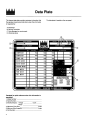
To the Installer
This machine is designed for indoor use only.
DO NOT install the machine in an area where a
water jet could be used to clean or rinse the machine. Failure
to follow this instruction may result in serious electrical shock.
WATER CONNECTIONS
(Water Cooled Units Only)
An adequate cold water supply must be provided with a hand
shut-off valve. On the underside rear of the base pan, two
3/8” I.P.S. water connections for inlet and outlet have been
provided for easy hook-up. 1/2” inside diameter water lines
should be connected to the machine. (Flexible lines are
recommended, if local codes permit.) Depending on local
water conditions, it may be advisable to install a water
strainer to prevent foreign substances from clogging the
automatic water valve. There will be only one water “in” and
one water “out” connection. DO NOT install a hand shut-off
valve on the water “out” line! Water should always flow in this
order: first, through the automatic water valve; second,
through the condenser; and third, through the outlet fitting to
an open trap drain.
AIR COOLED UNITS
Air cooled units require a minimum of 6” (152 mm) of
clearance around all sides of the freezer to allow for
adequate air flow across the condenser(s). Failure to allow
adequate clearance can reduce the refrigeration capacity of
the freezer and possibly cause permanent damage to the
compressor.
ELECTRICAL CONNECTIONS
Each freezer requires one power supply for each data label.
Check the data label on the freezer for fuse, circuit ampacity
and electrical specifications. Refer to the wiring diagram
provided inside of the electrical box, for proper power
connections.
050817
2
In the United States, this equipment is intended to be
installed in accordance with the National Electrical Code
(NEC), ANSI/NFPA 70--1987. The purpose of the NEC code
is the practical safeguarding of persons and property from
hazards arising from the use of electricity. This code contains
provisions considered necessary for safety. Compliance
therewith and proper maintenance will result in an installation
essentially free from hazard!
In all other areas of the world, equipment should be installed
in accordance with the existing local codes. Please contact
your local authorities.
Stationary appliances which are not equipped with a power
cord and a plug or other device to disconnect the appliance
from the power source must have an all--pole disconnecting
device with a contact gap of at least 3 mm installed in the
external installation.
CAUTION: THIS EQUIPMENT MUST BE
PROPERLY GROUNDED! FAILURE TO DO SO CAN
RESULT IN SEVERE PERSONAL INJURY FROM
ELECTRICAL SHOCK!
Beater rotation must be clockwise as viewed looking into the
freezing cylinder.
Note: The following procedures should be performed by a
trained service technician.
To correct the rotation on a three-phase unit, interchange any
two incoming power supply lines at freezer main terminal
block only.
To correct rotation on a single-phase unit, change the leads
inside the beater motor. (Follow the diagram printed on the
motor.)
Electrical connections are made directly to the terminal
block. The terminal block is provided in the main control box
located behind the lower front trim.
To the Operator
The freezer you have purchased has been carefully
engineered and manufactured to give you dependable
operation. The Taylor Model 337, when properly operated
and cared for, will produce a consistent quality product. Like
all mechanical products, this machine will require cleaning
and maintenance. A minimum amount of care and attention
is necessary if the operating procedures outlined in this
manual are followed closely.
This Operator’s Manual should be read before operating or
performing any maintenance on your equipment.
Your Model 337 will NOT eventually compensate for and
correct any errors during the set-up or filling operations.
Thus, the initial assembly and priming procedures are of
extreme importance. It is strongly recommended that all
personnel responsible for the equipment’s operation study
these procedures together in order to be properly trained and
to make sure that no misunderstandings exist.
If you require technical assistance, please contact your local
authorized Taylor Distributor.
If the crossed out wheeled bin symbol is affixed to
this product, it signifies that this product is compliant with the
EU Directive as well as other similar legislation in effect after
August 13, 2005. Therefore, it must be collected separately
after its use is completed, and cannot be disposed as
unsorted municipal waste.
The user is responsible for returning the product to the
appropriate collection facility, as specified by your local code.
For additional information regarding applicable local laws,
please contact the municipal facility and/or local distributor.
COMPRESSOR WARRANTY
DISCLAIMER
The refrigeration compressor(s) on this machine are
warranted for the term indicated on the warranty card
accompanying this machine. However, due to the Montreal
Protocol and the U.S. Clean Air Act Amendments of 1990,
many new refrigerants are being tested and developed, thus
seeking their way into the service industry. Some of these
new refrigerants are being advertised as drop-in
replacements for numerous applications. It should be noted
that, in the event of ordinary service to this machine’s
refrigeration system, only the refrigerant specified on the
affixed data label should be used. The unauthorized use
of alternate refrigerants will void your compressor warranty.
It will be the owner’s responsibility to make this fact known to
any technician he employs.
It should also be noted that Taylor does not warrant the
refrigerant used in its equipment. For example, if the
refrigerant is lost during the course of ordinary service to this
machine, Taylor has no obligation to either supply or provide
its replacement either at billable or unbillable terms. Taylor
does have the obligation to recommend a suitable
replacement if the original refrigerant is banned, obsoleted,
or no longer available during the five year warranty of the
compressor.
The Taylor Company will continue to monitor the industry and
test new alternates as they are being developed. Should a
new alternate prove, through our testing, that it would be
accepted as a drop-in replacement, then the above
disclaimer would become null and void. To find out the
current status of an alternate refrigerant as it relates to your
compressor warranty, call the local Taylor Distributor or the
Taylor Factory. Be prepared to provide the Model/Serial
Number of the unit in question.
050817
3
Safety
We at Taylor Company are concerned about the safety of the
operator when he or she comes in contact with the freezer
and its parts. Taylor has gone to extreme efforts to design and
manufacture built-in safety features to protect both you and
the service technician. As an example, warning labels have
been attached to the freezer to further point out safety
precautions to the operator.
IMPORTANT -- Failure to adhere to the following
safety precautions may result in severe personal injury.
Failure to comply with these warnings may also damage the
machine and its components. Component damage will result
in part replacement expense and service repair expense.
To Operate Safely:
DO NOT operate the freezer without reading this
operator’s manual. Failure to follow this instruction may result
in equipment damage, poor freezer performance, health
hazards, or personal injury.
S
DO NOT operate the freezer unless it is properly
grounded.
S
DO NOT attempt any repairs unless the main
power supply to the freezer has been
disconnected.
S
DO NOT operate the freezer with larger fuses
than specified on the freezer data label.
Failure to follow these instructions may result in electrocution
or damage to the machine. Contact your local authorized
Taylor Distributor for service.
DO NOT use a water jet to clean or rinse the freezer.
Failure to follow this instruction may result in serious
electrical shock.
S
DO NOT allow untrained personnel to operate
this machine.
S
DO NOT operate the freezer unless all service
panels and access doors are restrained with
screws.
S
DO NOT remove the door, beater and blades, or
drive shaft unless all control switches are in the
OFF position.
S
DO NOT put objects or fingers in door spout.
Failure to follow these instructions may result in
contaminated product or severe personal injury to fingers or
hands from hazardous moving parts.
USE EXTREME CAUTION when removing the
beater assembly. The scraper blades are very sharp and
may cause injury.
This freezer must be placed on a level surface.
Failure to comply may result in personal injury or equipment
damage.
DO NOT obstruct air intake and discharge openings:
A minimum of 6” (152 mm) air space is required on both sides
and rear, and 4--1/4” (108 mm) on bottom. Failure to follow
this instruction may cause poor freezer performance and
damage to the machine.
This freezer is designed to operate indoors, under normal
ambient temperatures of 70_ --75_F (21_ --24_C). The
freezer has successfully performed in high ambient
temperatures of 104_F (40_C) at reduced capacities.
NOISE LEVEL: Airborne noise emission does not exceed 78
dB(A) when measured at a distance of 1.0 meter from the
surface of the machine and at a height of 1.6 meters from the
floor.
050817
5
30
+ Available Separately
012864
X35466
+WASHER-BEARING LOCK
BEATER A.-2.8QT-HELICORE
013073
023316
013071
040040-010
040040-028
040040-029
040040-040
014218
047701-27
BRUSH-DRAW VALVE 1”ODX2”X17”L
BRUSH-MIX PUMP BODY-3”X7”WHITE
BRUSH-REAR BRG 1IN.DX2IN.LGX14
CABLE-RIBBON-50C - 5”L
CABLE-RIBBON-14C - 45”L
CABLE-RIBBON-7C - 35”L
CABLE-RIBBON-20C - 14”L
CAP-DESIGN-1.010”ID-6 POINT
COMPRESSOR TL3G-R134A
036048
036047
048132
048623
036052
+RELAY-START-COMPRESSOR
+CAPACITOR-RUN- 35UF/440V
CONDENSER-AC-19X14X2.5 4 ROW
CONDENSER-STATIC
047519-
+CAPACITOR-START-135-155UF/330V
COMPRESSOR-AHA-2490ZXD-AH556
047702-27
013072
BRUSH-DOUBLE ENDED-PUMP&FEED T
+RELAY-START-COMPRESSOR-TL3G
040322-005
BLOCK-TERMINAL-PLUG 10P .2 SIP
047704
040322-004
BLOCK-TERMINAL-PLUG 8P .2 SIP
+KIT-MOUNTING-COMPRESSOR
040322-002
BLOCK-TERMINAL-PLUG 6P .2 SIP
047739
040322-001
BLOCK-TERMINAL-PLUG 4P .2 SIP
+COVER-TERMINAL-COMPRESSOR
024156
BLOCK-TERMINAL 7 POLE GREEN
047703
039422
BLOCK-TERMINAL 2P
+CAPACITOR-START-60UF-220/275V
023875
BELT-AX40
035480
028991
+NUT-BRASS BEARING
+BLADE-SCRAPER-PLASTIC 13-1/4L
028992
031324
+GUIDE-DRIP SEAL
050216
BEARING-REAR SHELL *NICK.PLATE
PART
NUMBER
BEARING-FRONT
DESCRIPTION
1
1
1
1
1
1
1
1
1
1
1
3
1
1
1
1
1
1
1
1
1
1
2
1
1
1
4
4
2
2
2
2
2
2
QTY.
103
103
103
103
103
512
103
103
103
103
512
000
103
103
103
103
000
000
000
000
103
103
103
103
103
103
000
000
103
000
000
000
000
000
WARR.
CLASS
DANFOSS SYSTEM
208-230/60/1
208-230/60/1
208-230/60/1
TECUMSEH
SHR
SHR
SHR
SHR
SHR
REMARKS
PARTS
UPDATE
J5075161/Up -- HP62 Refrigerant
Parts List
100409
+ Available Separately
31
1
044214
032484
038374
X38062-SER
038221
DECAL-DEC-TWIN-SS
DECAL-POWER SWITCH
DECAL-TROUBLESHOOTING
DISPLAY-LIQUID CRYSTAL
028804
015872
033662
029639-BLK
HANDLE-ADJUSTABLE
O-RING-1/4 OD X .070W 50 DURO
SCREW-ADJUSTMENT
+NUT-5/16-24 18-8 SS JAM
CAP-DESIGN-1.010”ID-6 POINT
BEARING-FRONT
KIT A.-TUNE UP-3 SPOUT-NON HT
014218
050216
X49463-5
X25796
HINGE A.-MOTOR
HOOD *337*
X41816
045606
+HOLDER-FUSE
GUIDE A.-DRIP PAN *3337*
047332
FUSE-7 AMP - IN LINE
042934
013739
EYELET-RESET BUTTON
GEAR A.*REDUCER-DUAL-OUTPUT
048901
DRYER-FILTER-HP62-3/8 X 1/4S
048926
047699
DRYER-CAP. TUBE-HP62/R134A
GASKET-DOOR HT 4”-DOUBLE
014402
X18303
016272
X20683
016137
+O-RING-7/8 OD X .103W
+VALVE A.-DRAW
+O-RING-5/16 OD X .070W
+ROD A.-PIVOT
+O-RING-3/8 OD X .070W
028805
X33687
+HANDLE A.-DRAW-ADJ.
+PLUG-PRIME
021521
X51532-15
DOOR A.-3 SPOUT
DECAL-FREEZER DOOR
044553-
DIAGRAM-WIRING *337*
+LENS-DISPLAY
1
019029
DECAL-CLEAN INST.-HOPPER
3
2
1
1
1
1
2
1
1
2
1
1
6
3
1
1
4
2
3
3
3
3
3
1
1
1
1
1
1
1
2
041682-GRY
2
012721
QTY.
COVER-HOPPER 14QT GRAY
PART
NUMBER
COUPLING-DRIVE 3/4 HEX X 1-7/8
DESCRIPTION
000
000
000
103
103
212
000
103
000
000
000
000
000
103
000
103
000
103
000
000
000
103
103
000
103
000
000
103
000
000
000
000
103
103
WARR.
CLASS
HOOD IS NOT A SEPARATE SERVICE ITEM
SHR
SYMBOL J9109999/ PRIOR
REMARKS
148
PARTS
UPDATE
+ Available Separately
32
021522051744-
MOTOR-1.5 H.P.
MOTOR-FAN 80 WATT 1550 RPM CW
022465-100
ORIFICE
023348
027504
X41844
X44247
X48596
044287
048487
X44276
PAIL-MIX 6 QT
PAN-DRIP 17-1/4”LONG
PAN A.-HINGED
PANEL A.-FRONT *337*
PANEL A.-UPPER SIDE RIGHT
PANEL-REAR
PANEL-SIDE-RIGHT & LEFT
PLATE A.-DEC-337
016137
034383
NUT-STUD *460-664-754-56*SHORT
+O-RING-3/8 OD X .070W
034382
1
1
1
1
1
1
1
1
2
2
2
2
1
019624
+CAPACITOR-RUN 4UF/370V
NUT-STUD *460-664-754-56*LONG
1
1
1
041401-
1
1
1
1
1
1
4
5
1
1
1
2
1
6
1
6
4
6
2
QTY.
047279
+FAN-5 BLADE 12” PUSH
MOTOR-FAN - 120W
051785
044869-M
MAN-OPER 337
+CAPACITOR-RUN- 4UF-440V
047518
LUBRICANT-TAYLOR 4 OZ.
047279
017471
+FAN-5 BLADE 12” PUSH
013458
048260-WHT
TOOL- 0-RING REMOVAL
LOUVER-SIDE - LEFT
032560
SEAL-DRIVE SHAFT
LEG-4” W/O-RING
034698
SEAL-DRAW VALVE
051433
014402
O-RING-7/8 OD X .103W
LABEL-WARN-COVER
016272
O-RING-5/16 OD X .070W
052632
016137
O-RING-3/8 OD X .070W
LABEL-SW-POWER-OFF/ON-SYMBOLS
018572
O-RING-.643 OD X .077W
032749
018550
LABEL-DOOR CAUTION
048926
O-RING .291ID X .080W
PART
NUMBER
GASKET-DOOR HT 4”-DOUBLE
DESCRIPTION
103
103
103
103
103
103
103
000
000
103
103
103
103
103
103
103
103
103
212
000
000
103
103
000
000
000
000
000
000
000
000
000
000
000
000
WARR.
CLASS
PRIOR TO 6/01/00
PRIOR TO 6/01/00
6/01/00/ UP
6/01/00/ UP
PANELS & CONTROL BOX
J9110000/ UP
REMARKS
148
PARTS
UPDATE
+ Available Separately
33
X45047-SER
PROBE A.-THERMISTOR - HOPPER
027822
X53487-SER
PULLEY-2AK74-5/8 BORE
PCB A.-CONTROL *UVC2*
X40875
X40876
CHIP-SOFTWARE UVC2 U10 ENGLISH
CHIP-SOFTWARE UVC2 U11
2
033235
032560
SHAFT-BEATER
BRACKET A.-SPRING RETURN
X38257
038650
X38547
SWITCH A.-DRAW *SELF CLOSING*
ARM-SWITCH-DRAW-RIGHT
041950-
STARTER-1 PHASE-4.5 TO 7 A
038649
048489
SKIRT-AIR FLOW
ARM-SWITCH-DRAW-LEFT
022765
SHIELD-SPLASH
022822
X45001
SHELL A.-INSULATED *339*
+STUD-NOSE CONE
X53251
SHELL A.-INSULATED *339* (NEW)
+SEAL-DRIVE SHAFT
2
041082
SANITIZER KAY-5 125 PACKETS
1
1
1
1
1
1
1
4
1
1
1
1
012725-33
RELAY-3 POLE-20A-208/240 50/60
1
1
1
X44295-SER
X44863-SER
PCB A.-UNIVERSAL CONTROL
1
1
1
1
1
1
1
1
1
1
1
1
1
1
2
2
QTY.
PCB A.-INTERFACE
X40836
CHIP-SOFTWARE
Includes:
X45313-SER
X40873
CHIP-SOFTWARE UVC2 CHIP-SEL
PCB A.-CONTROL (OLD)
X40872
X51169-SER
PCB A.-UVC2
CHIP-SOFTWARE UVC2 DISPLAY
X40785
CHIP-SOFTWARE
Includes:
034238
038061-BLK
X45046-SER
PULLEY-2AK20 X 5/8 BORE
PROBE-THERMISTOR-BARREL-2% TOL
PROBE A.-THERMISTOR - BARREL
039470-BLK
X41348
PROBE-THERMISTOR-HOPPER-2% TOL
X30922
PROBE A.-MIX OUT
PART
NUMBER
PROBE A.-MIX *SQUARE*
DESCRIPTION
103
103
103
103
103
103
103
103
512
512
000
103
000
103
212
212
103
212
103
103
103
103
212
103
212
103
103
103
103
103
103
103
103
WARR.
CLASS
DEFLECTOR
PRIOR TO J9070000
J9070000/UP
PRIOR TO J9071700
PRIOR TO J9071700
PRIOR TO J9071700
J9071700/UP
J9071700/UP
J9071700/UP (REPLACES X45313-SER)
GEAR
BEATER MOTOR
REMARKS
145
145
144
144
144
144
144
144
PARTS
UPDATE
+ Available Separately
34
038923
038924
X39269
SPRING-RETURN-LEFT-TWIN TWIST
SPRING-RETURN-RIGHT-TWIN TWIST
SWITCH A.-DRAW-TWIN TWIST
030629024295
045754
020157
044286
044280
044281
X32824-2
SWITCH-PUSHBUTTON/NEON DISPLAY
SWITCH-TOGGLE-DPDT-ON NONE ON
TRANS-CONT. 40VA
TRAY-DRIP - 16-7/8L X 5-1/8
TRIM-FRONT
TRIM-REAR CORNER L.
TRIM-REAR CORNER R.
TUBE A.-FEED-INNER
4
018572
029406
044404
047016
022665
044335-27
047572013808
+O-RING-OUTER FEED TUBE
VALVE-ACCESS 1/4 X 3/8 SOLDER
VALVE-ACCESS 1/4FL X 1/4SOLDER
VALVE-ACCESS-1/4 MFLX1/4 S-90
VALVE-EPR 1/4S
VALVE-EXP-PULSE 3/8S 240VAC
VIDEO-TRAIN FILM-SS 337
WASHER-PLASTIC PIVOT
4
1
2
1
2
1
1
2
6
2
1
1
1
1
1
1
1
1
1
2
4
1
1
1
1
2
2
1
1
4
1
QTY.
X34641
TUBE A.-FEED-OUTER
018550
048230
SWITCH-PRESSURE 440 PSI-SOLDER
+O-RING-INNER FEED TUBE
044520
SWITCH-MEMBRANE - 5 POSITION - 8”L
039252
038922
SPRING-EXTENSION.375X.045X1.00
SWITCH-LEVER-SPDT-11A-125-277V
039267
SCREW-8-32X3/8 HEX HD TYPE 23
042604
038254
ROD-SPRING RETAINER
SCREW-4-40 X1/2”TAPTITE PAN HD
038484
PIN-PIVOT-DRAW SWITCH
039264
032190
BRACKET-DRAW SWITCH-TWIN TWIST
X38252
E-RING 1/4
PART
NUMBER
BRACKET A.-SWITCH *338-39-754
DESCRIPTION
000
000
103
103
103
103
103
000
103
000
103
103
103
103
103
103
103
103
103
103
103
000
103
103
103
103
103
000
103
103
000
103
WARR.
CLASS
MAIN H/S & AUX L/S
EPR
MAIN L/S
POWER
REMARKS
PARTS
UPDATE
+ Available Separately
35
036048
036047
047178-34
CAPACITOR-START 135/155UF/330VOLT
RELAY-START COMPRESSOR
MOTOR-FAN 100W 220-240VOLT
PULLEY 2AK27 X .625
011545
019624
029439
CAPACITOR-RUN-35UF/370VOLT
+CAPACITOR-RUN- 4UF-370V
023876
BELT-AX41
50Hz
046686
VALVE-WATER 3/8 REG/HEAD PRESSURE
013043
+FAN-5 BLADE 10” PUSH
048231
015184-
SWITCH-PRESSURE 350PSI-SOLDER
049309
MOTOR-FAN -25W 230VOLT
PART
NUMBER
CONDENSER-W/C
WATER COOLED
DESCRIPTION
1
1
1
1
1
1
2
1
1
1
1
1
QTY.
103
103
103
103
103
103
000
013
103
103
103
103
WARR.
CLASS
BEATER MOTOR
220-240/50/1 COMPRESSOR
220-240/50/1 COMPRESSOR
220-240/50/1 COMPRESSOR
REMARKS
PARTS
UPDATE
Model 337
044553--27G
7/16/12
Model 337
044553--33G
7/16/12
Model 337
044553--40
7/16/12
Model 337
044553--62G
7/16/12
044869--M