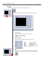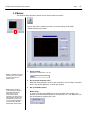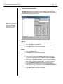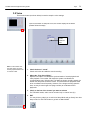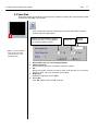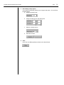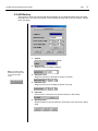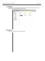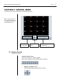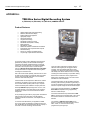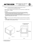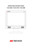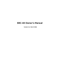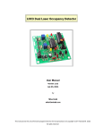
1
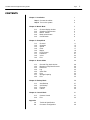
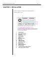
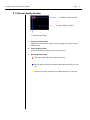
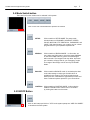
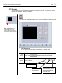
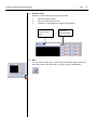
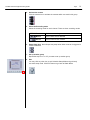
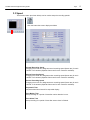
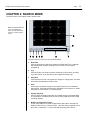
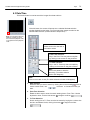
TATUNG TDR series Digital Recording System
Page
TDR-22XX series
Digital Recording System
Installation and Operation Manual
V 1.01
TATUNG COMPANY OF AMERICA. INC
2850 El Presidio St., Long Beach CA 90810 USA
Tel: 310-637-2105 Fax: 310-638-2180
www.tatungusa.com
0
TATUNG TDR series Digital Recording System
Page
0
TATUNG TDR series Digital Recording System
Page
CONTENTS
Chapter 1: Installation
Step 1 Connect the cables
Step 2 Turn on the system
Chapter 2: Watch Mode
2.1
2.2
2.3
2.4
2.5
Channel display window
Selection of Split screen
Motion Tracker
Mode switch button
On/Off button
Chapter 3: Setup Mode
3.1
3.2
3.3
3.4
3.5
3.6
3.7
3.8
3.9
Channel
Schedule
Speed
Color
Motion
P/T/Z Control
Password
Voice
Exit
Chapter 4: Search Mode
4.1
4.2
4.3
4.4
4.5
4.6
4.7
4.8
Channel Play back window
Buttons on Play Back Console
Date/Time
Log
Save Disk
Print
Storage Capacity
Exit
Chapter 5: Backup Mode
5.1
5.2
5.3
5.4
Auto Backup
AVI Backup
Explorer
Cancel
Chapter 6: Control Mode
6.1
6.2
Appendix
A:
B:
1
2
2
3
5
6
7
8
8
9
11
13
15
17
18
20
21
24
25
26
28
29
30
32
33
34
35
35
36
37
39
40
40
41
Camera Control
Exit
41
42
Technical Specification
Connector Configuration
43
46
0
TATUNG TDR series Digital Recording System
Page
0
TATUNG TDR series Digital Recording System
Page
CHAPTER 1: INSTALLATION
Place the Digital Recording System on the flat surface or
mount it on the 19” rack.
* For TDR-2209 there are only 9 camera Inputs and 9 Loop through outputs on
the back board. For TDR-2204 there are only 4 camera Inputs and 4 Loop
through outputs on the back board.
1.
2.
3.
4.
5.
6.
7.
8.
9.
10.
11.
12.
13.
14.
15.
16.
17.
18.
Camera Inputs
Loop Through output
Reserved
CCTV Monitor output
Alarm Inputs
Alarm Outputs
Audio In
Microphone Jack
Audio Out
COM series port
Printer (LPT) port
PC Monitor Output
Mouse (PS/2)
Keyboard (PS/2)
Network port (RJ-45)
AC Power Input
115/230 VAC Power Switch (option)
Power Supply Switch (option)
1
TATUNG TDR series Digital Recording System
Page
2
Step 1: Connect the Cables
Connect all the necessary connector and signal cables into the correct ports.
Alarm In/Out
Audio In
Camera In
Audio Out
Camera Out
CCTV
Monitor Out
PC
Monitor
Output
Network Port
Power In
Protect
Socket
and
LPT
* For TDR-2209 there are only 9 camera Inputs and 9 Loop through outputs on
the back board. For TDR-2204 there are only 4 camera Inputs and 4 Loop
through outputs on the back board.
Step 2: Turn on the System
Turn on the power by push the power button on the front panel.
Removable Storage
Reset
Power
CDRW
TATUNG TDR series Digital Recording System
Page
CHAPTER 2: WATCH MODE
Turn on the system. The main screen of TATUNG TDR-22XX series appears as below.
Note: For TDR-2209 there are
only 9 channels split the screen.
For TDR-2204 there are only 4
channels split the screen
The buttons and icons on the screen are described below:
Note: For TDR-2209, the Button
of 9 Sequence and the button of
16 will show the all 9 channel at
same time. : For TDR-2204, the
Button of 4 Sequence, the button
of 9 Sequence and the button of
16 will show the all 4 channel at
same time.
1.
Company LOGO
This is the logo of TATUNG Company of America.
2.
DATE/TIME Window
This window displays the date and time.
3.
1 Sequence Button
Click to select the 1-window (1x1) format. Only 1 camera can be
displayed at a time. The sequential dwell time can be adjusted in
SETUP mode.
4.
4 Sequence Button
Click to select the 4-window (2x2) format. Up to 4 cameras can be
displayed at the same time. The sequential dwell time can be adjusted
in SETUP mode.
5.
9 Sequence Button
Click to select the 9-window (3x3) format. Up to 9 cameras can be
displayed at the same time. The sequential dwell time can be adjusted
in SETUP mode.
6.
16 Button
Click to select the 16-window (4x4) format. Up to 16 cameras can be
displayed at the same time. The sequential dwell time can be adjusted
in SETUP mode.
3
TATUNG TDR series Digital Recording System
Page
4
7.
Full SCR Button
This button allows you to hide all buttons and icons and enlarge the
display windows to the FULL SCREEN. You have to right click to get
back to normal. Once you get the full screen, if you LEFT click, the
screen can not go back to normal, instead, the picture the mouse
arrow sitting on will be enlarged to full screen.
8.
Motion Button
Click to enable the motion tracking function. This is a very powerful
function which allows you to track a moving object from one channel
to another. All image windows this object passed by will be enlarged
one by one.
9.
Setup Button
Click to switch to SETUP MODE. The setup mode includes buttons of
CHANNEL, SCHEDULE, SPEED, COLOR, MOTION, P/T/Z
PROTOCOL, PASSWORD, and VOICE. With these buttons your
system can be custom- programmed to fit your operation needs.
10.
Search Button
Click to switch to SEARCH MODE. In this mode, you may either use
LOG button to check the image database or use DATE/TIME button
to get the recorded images within seconds. The images found may
either print out or save to a floppy disk for your emergency needs.
The usage of the storage can be found by STORAGE button.
11.
Backup Button
Click to switch to BACKUP MODE. In this mode, you may either
choose auto-backup function to save images to a second removable
hard disk or choose AVI backup function to save images onto a
CDRW available from this system.
12.
Control Button
Click to switch to CONTROL MODE. In this mode the
PAN/TILT/ZOOM of each camera can be controlled by clicking the
buttons on the screen.
13.
On/Off Button
Click to turn off the entire system.
14.
Display windows
Display camera images on 1, 4, 9 or 16 windows depending on your
selection. Left click a window will enlarge the picture in that specific
window. And left click again the picture will go back to the normal
size. RIGHT click any window will hide all buttons and icons and
enlarge all pictures. And right click again will go back to normal
15.
On Screen Display (OSD)
Display the camera name and recording status. The recording status
indicates camera active or inactive and the recording method
(continuous recording, motion recording or alarm recording).
TATUNG TDR series Digital Recording System
Page
2.1 Channel display window
1. Channel (Camera) name
2. Image display window
3. Record status lamp
1.
Channel (Camera) name
Identify the name for each channel. You may assign the channel name in
SETUP mode.
2.
Image Display window
This area displays the image comes from the camera.
3.
Recording status lamp
This lamp turns red at consecutive recording
When motion recording, this lamp becomes blue and white. (on and
off)
At sensor recording, this lamp turns yellow and white. (on and off)
5
TATUNG TDR series Digital Recording System
Page
6
2.2 Selection of Split screen
Selection of window division mode that is available in 1 division window (sequence from channel 1
to channel 16), 4 window, 9 window, 16 window, and Full screen display.
Click on the one of these buttons to perform the function
Note: At all Ch Display, left
click a specific camera, the
image of this camera will be
enlarged without sequencing.
And left-click again can go
back to the normal status.
one-window Sequence
four-window Sequence
Note: For TDR-2209, the button
of 9 Sequence and the button of
16 will show the all 9 channel at
same time. : For TDR-2204, the
button of 4 Sequence, the button
of 9 Sequence and the button of
16 will show the all 4 channel at
same time.
nine-window Sequence
all channel
Note: You can always use
right-click on mouse to
switch between these Full
screen status and normal
screen status.
FULL screen
Click this button to hide all buttons and icons and enlarge the display
windows to FULL screen. You must right click on mouse or touch pad to
go back to the normal.
TATUNG TDR series Digital Recording System
Page
7
2.3 Motion Tracker
This function allows you to track the path of a moving object from one channel to another. All image
windows this object passed by will be enlarged. Therefore, the object will always display on an
enlarged window.
Click on this button to enable the motion tracking function.
Note: To enable this
function, all channels
need to be programmed
to motion recording.
TATUNG TDR series Digital Recording System
Page
8
2.4 Mode Switch button
There are four function modes can be selected in this system.
Click on the one of these buttons to perform the function
SETUP:
Click to switch to SETUP MODE. The setup mode
includes buttons of CHANNEL, SCHEDULE, SPEED,
COLOR, MOTION, P/T/Z PROTOCOL, PASSWORD, and
VOICE. With these buttons your system can be customprogrammed to fit your operation requirements.
SEARCH:
Click to switch to SEARCH MODE. . In this mode, you
may either use LOG button to check the image database
or use DATE/TIME button to get the recorded images
within seconds. The images found may either be printed
out or saved to a floppy disk for your emergency needs.
The usage of the storage can be found by STORAGE
button.
BACKUP:
Click to switch to BACKUP mode. It can backup the data
to the other storage or other type of media which is
available for this system. This mode include the autobackup function, immediate AVI type backup function and
have a windows explorer opened for your convenience.
CONTROL: Click to switch to CONTROL MODE. In this mode the
PAN/TILT/ZOOM of each camera can be controlled
by clicking the buttons on the screen.
2.5 ON/OFF Button
Click on this button and click on “YES” as the system prompt out “ARE YOU SURE?”
to shutdown the DVR system.
TATUNG TDR series Digital Recording System
Page
9
CHAPTER 3: SETUP MODE
The first screen of the setup mode will be the channel setting as the following picture
Note: For TDR-2209, CH 10 to
CH 16 will be empty by the
factory’s setting. For TDR-2204,
CH 05 to CH 16 will be empty by
factory’s setting
The control buttons contained in the main screen are described below:
1.
Channel
Click on this button to setup the channel and channel name. There are two
different ways to setup the channel-automatically scan and manually
designate. You can also set the name for each channel.
2.
Schedule
Click this button to setup the recording schedules. There are 16 recording
groups and three recording modes (continuous, motion, sensor) can be
separately set up for your application. Alarm output can also be set up
separately.
3.
Speed
Click to assign the recording speed and other options. The recording
speeds include speeds on normal recording, motion recording, and sensor
recording. You can also set up the times for display sequence, post alarm
and post motion in this mode.
4.
Color
Click to adjust the image color, including the adjustment of Brightness,
Contrast, Color (saturation), and TINT for each individual channel.
5.
Motion
Click to assign the motion function. You can set up each individual
channel’s motion detection area (up to 10 zones for each channel),
sensitivity, and the beep time for motion detection.
TATUNG TDR series Digital Recording System
Page
10
6.
P/T/Z camera protocol
Click to setup the communication port and protocol used to communicate
between Tatung’s DVR and the camera connected.
7.
Password
Click on this button to setup the user name and password for access security.
The passwords are divided in SETUP, VIEWER, SHUTDOWN, and REMOTE
four levels. Hiding camera can also be programmed with this setup.
8.
Audio
Click to setup the audio recording function.
9.
Exit
Click to exit to the setup mode and back to watch mode.
TATUNG TDR series Digital Recording System
Page
11
3.1 Channel
This function button (as shown below) can be used to setup the channels. There are two different
types of channel setting, manual or automatic.
Click this button to start the channel setup and the screen will be shown as below.
Note: For TDR-2209, CH 10 to
CH 16 will be empty by the
factory’s setting. For TDR-2204,
CH 05 to CH 16 will be empty by
factory’s setting
1.
Setup the Channel
You can setup the channel either by auto setting or manual setting.
Auto
Setting
Click on the
Manual
Setting
Select the Board (B01-B04) and Channel
(C01-C04) from the list to setup the
Channel Name
setup will be executed automatically
CH01
First Channel
This is the first
Board and first
Camera
Click to have the list.
Select the Board # and
Camera # from the list.
Then left-click
TATUNG TDR series Digital Recording System
2.
Page
12
Setup the name
Setup the channel name by following the procedure
1.
2.
3.
Click the channel number
Key in the name of the channel
Limited to 14 characters and number including space.
2. Key in the
channel name
1. Click to
choose channel
here
3.
EXIT
You may click any other icon to exit Channel Setup Mode and go directly into
other setup mode. Click EXIT button, you will be back to Watch Mode.
TATUNG TDR series Digital Recording System
Page
13
3.2 Schedule
This function button (as shown below) is used to setup the schedules.
Click on this button to start schedule setup and the screen will display as
follow. (Please follow the 7 steps below)
Note: For TDR-2209, Camera’s
CH 10 to CH 16 and Motion’s
CH 10 to CH 16 will be useless
even you activate it. For TDR2204, Camera’s CH 05 to CH 16
and Motion’s CH 05 to CH 16 will
be useless even you activate it.
Note: Alarm Out 09 to 16 was
not configured in all TDR-22XX
series DVR.
Note: The shutdown time is
to set the time for turning off
the system, which is different
to the restart system.
1.
Select the Group
Select the Group number (total 16 groups are available and
programmable).
2.
Activate Group
Activate the group by checking the box.
3.
Schedule the Recording DATE/TIME and DVR Shutdown Time
• Setup the days of the week (Sunday to Saturday) by checking the box of the
day.
• If you want to assign the recording time (default is 24 hours), setup [Start
Time] and [End Time] by using military time system. (00:00 to 00:00 means
24 hours).
• If you want to assign the shutdown time, check the box of Shutdown Time
and setup the time.
TATUNG TDR series Digital Recording System
Page
14
4.
Activate the camera
Click the camera icon to activate the cameras which are used in this group.
5.
Select the Recording mode
Select the recording mode for each channel. There are three recording modes.
DEFAULT
Continuous recording
Motion
Record while motion detected
Sensor
Record while Sensor is active
6.
Setup Alarm Out: Alarm Output may setup when either a sensor is triggered or
motion is detected.
7.
Set up another group
Repeat the step from 1 to 5 if you want to set up another group.
8.
Exit
You may click any other icon to exit Schedule Setup Mode and go directly
into other setup mode. Click EXIT button to go back to Watch Mode.
TATUNG TDR series Digital Recording System
Page
3.3 Speed
This function button (as shown below) can be used to setup the recording speeds.
Click this button the screen displays as below.
Normal Recording Speed
Dragging the cursor can designate normal recording speed (frame rate) for each
camera or all cameras (Separate frame rate for each camera is available).
Motion Recording Speed
Dragging the cursor can designate motion recording speed (frame rate) for each
camera or all cameras (Separate frame rate for each camera is available).
Sensor Recording Speed
Dragging the cursor can designate sensor recording speed (frame rate) for each
camera or all cameras (Separate frame rate for each camera is available).
Sequential Time
Adjust the dwell time interval for sequential display.
Post Motion Time
Keep recording for a period of time after motion detection is over.
Post Alarm Time
Keep recording for a period of time after sensor alarm is finished.
15
TATUNG TDR series Digital Recording System
Page
16
MISC
Check on the box if you want the following features to be enabled.
Sensor Beep
Activate beep sound when sensor is triggered.
Proportion
When activated, only 1, 4, 9, 16 divisions are available, to
keep the horizontal and vertical ratio of each channel window.
Motion Log
Activated Motion log function.
Recording While
Searching
Continue to record when the system in search mode.
Removable HDD
System Will BEEP when the removable HDD is almost full.
Image Quality
Dragging the cursor can adjust the compression rate, the higher the compression the
worse the image quality. The recorded image with best quality (100%) is clear and
vivid. But the size of a frame is the largest (15KB-20KB). At lower percentage of
quality (higher compression rate) image quality is relatively low. But the size of a
frame is relatively small (3KB-8KB). 34%-50% of image quality is recommended.
Frame Size**
Compression Rate
Image Quality
Range
HIGH
LOW
0%
10%
20%
30%
40%
50%
60%
70%
80%
90%
100%
2400-7200 byte
2600-8100 byte
2900-9300 byte
3500-10300 byte
4100-12000 byte
5000-14000 byte
6000-16000 byte
6600-17000 byte
8200-20000 byte
9200-22000 byte
14000-24000 byte
Average
5.0 KB
5.5KB
6.0 KB
7.0 KB
8.0 KB
9.5 KB
11.0 KB
12.0 KB
14.0 KB
16.0 KB
19.0 KB
*Frame size may vary from image to image according to the situation of site
EXIT
You may click any other icon to exit Speed Setup Mode and go directly into other
setup mode. Click EXI T button to go back to Watch Mode.
TATUNG TDR series Digital Recording System
Page
3.4 Color
This function button (as shown below) is used to setup the colors.
Click this button to setup the color, the screen will be shown as below.
1.
Select channel
Select the channel (from 1 to 16) you want to adjust.
2.
Adjust the Color
Drag the cursor to adjust the followings for each channel.
Bright:
Const:
Color:
Tint:
Default color:
3.
Adjust the brightness.
Adjust the contrast.
Adjust the color saturation.
Adjust the tint.
Load default color value.
EXIT
You may click any other icon to exit Color Setup Mode and go directly
into other setup mode. Click EXIT button to go back to Watch Mode.
17
TATUNG TDR series Digital Recording System
Page
18
3.5 Motion
This function button (as shown below) can be used to setup the motions.
Click on this button to setup the motion, the screen display as the below
(Please following the 4 steps)
1.
Select channel
Select the channel from 1 to 16.
2.
Set up motion detection zone.
Setup the motion detection zone for each channel by click and drag. It would be
seen in red square (Maximum 10 areas per camera).
3.
Set up the MISC options.
Note: If no detection zone was
defined, system will recognize
the whole windows as a
detection zone.
Note: After the camera is
motion activated in Schedule
Setup Mode and after the
detect zone is set, this
channel will be motionbeactivated in the define area. If
anything falls in this area, the
detected motion will be seen
in a lot of small blue squares.
And red wording “MOTION
DETECTION” will be blinking.
Motion beep
In motion recording mode, BEEP sound (if the speaker was included in the
system) can be activated/inactivated by checking the box or not. Beep time can
also be adjusted by dragging the cursor.
TATUNG TDR series Digital Recording System
Page
19
Sensitivity
Set the sensitivity of software motion detection. At highest sensitivity even very
trivial motion will be detected.
Clear all block
All of the detecting zones for a specific channel.
4.
EXIT
You may click any other icon to exit Motion Setup Mode and go directly
into other setup mode. Click EXIT button to go back to Watch Mode.
TATUNG TDR series Digital Recording System
Page
3.6 P/T/Z Protocol
This function button (as shown below) is used to setup P/T/Z Protocol.
Click on this button to setup the P/T/Z Protocol, the screen display as the
below
Click to choose a
manufacturer
brand from list
Click to assign
communication
port.
Please select the same protocol as that of your camera.
EXIT
You may click any other icon to exit Protocol Setup Mode and go directly into
other setup mode. Click EXIT button to go back to Watch Mode.
20
TATUNG TDR series Digital Recording System
Page
3.7 Password
This function button (as shown below) can be used to setup the password.
Click on this button to setup the Password.
Note: For TDR-2209, the Hide
Camera function CH 10 to CH 16
will be useless even you activate
it. For TDR-2204, the Hide
Camera function CH 05 to CH 16
will be useless even you activate
it.
•
Note: See next page for the
remote access password.
Password
There are five levels of password for security purpose.
(Please follow the steps below)
1. Select the password type.
2. Key in the new password. (From keyboard, mouse, or touch screen).
3. Click on “Apply” when finished or “Clear” to canceled
21
TATUNG TDR series Digital Recording System
•
Page
22
Remote username/password
Select the Remote Access in the Password Select window. An Input
Password window will be prompted up. After entering the password and
click OK, the following screen will be shown. TATUNG TDR series allow the
administrator to sign up remote users.
NOTE: To set up the Remote
username/password. The
system will ask the SETUP
password again to confirm
the authority of the user
§ Sign up
o
o
o
o
Click “Sign up” button will prompt the Register Account window.
Key in the New ID and Password.
Then click Entry button.
Click “Exit” button to leave above window.
§ Delete
o
o
o
Click on the user’s name in the Registered ID window above.
Click on “Delete” button.
Click “Exit” button to leave above window.
§ Edit User
o Click on user’s name in the Registered ID window above. The
user’s ID and Password will be shown in the “User information”
and “Select Hide camera” window.
o If you want to change the password, click the “Change Password”
button. After entering the new password, you have to confirm it.
Then click APPLY and OK in Account window to complete.
o If you want to hide the cameras for this user, check the box for
each camera or click on the button of either “Select All Camera” or
“Clear All Camera ”.
o Click “Exit” button to leave above window.
TATUNG TDR series Digital Recording System
Page
•
Hide Cameras
Check the box(es) to hide the channel(s) from the server site.
•
Restart Window
Check the box of the day and assign the time to restart the system.
Note: For TDR-2209, the Hide
Camera function of Remote
Client CH 10 to CH 16 will be
useless even you activate it. For
TDR-2204, the Hide Camera
function of Remote Client CH 05
to CH 16 will be useless even
you activate it.
EXIT
You may click any other icon to exit Password Setup Mode and go directly into
other setup mode. Click EXIT button to go back to Watch Mode.
23
TATUNG TDR series Digital Recording System
Page
24
3.8 Voice
This function button (as shown below) is used to setup the voice settings.
Click on this button to setup the voice, the screen display as the below
(Please follow the steps)
Audio
Channel
one
Note: To have a better voice
play back quality. The image
recording speed is better to set
to mote than 2 FPS.
1.
Check the box of “sound”
Check on this box to enable the sound recording.
2.
Adjust the “Play Sound Delay”
Adjust this number to coordinate the synchronization of sound playback and
video playback. The number 700 means the system coordinates the
synchronization every 700 seconds. The faster the image recording speed, the
smaller the delay time should be chosen. This means the two playbacks need
to be coordinated more frequently. However, if the image recording speed is
slow, we may choose longer time (large number) to coordinate the two
playbacks.
3.
Check on the box of the channel you want to activate
For TDR-22XX series, audio can be recorded only in channel one (01).
4.
EXIT
You may click any other icon to exit Voice Setup Mode and go directly into other
setup mode. Or click EXIT button to go back to Watch Mode.
TATUNG TDR series Digital Recording System
Page
3.9 Exit
Click on EXIT button to switch back to WATCH MODE after you complete all the setting in the
SETUP mode.
Note: You can always click on
the EXIT to switch back to
watch mode no matter what
function mode you are in.
25
TATUNG TDR series Digital Recording System
Page
26
CHAPTER 4: SEARCH MODE
The main screen of the search mode is shown below.
Note: For TDR-2209 there are
only 9 channels split the
screen. For TDR-2204 there
are only 4 channels split the
screen
The buttons and icons of the main screen are described below:
1.
Date/Time
Click on this button to search the images from Date and Time. A calendar
like data selection window including From-Time and To-Time will be
prompted up.
2.
Log
Click this button can check the sensor recording log and motion recording
log of the system. It can also search the images from these logs.
3.
Save Disk
Click this button to save a short period of images to a floppy disk. Channels
and frames are selectable in this function.
4.
Print
Click to print the specific image on the system printer as an immediately
data retrieve. Channels and frames are selectable in this function no matter
the printer is a local printer or a network printer.
5.
Storage Capacity
Click to check the usage information of the data storage (removable HDD).
The information includes both the sound recording capacity and the image
recording capacity.
6.
Buttons on Play Back Console
These control buttons are used to playback the data, Which includes the
starting of the record, 1 previous minute, 1 previous frame, playback, quick
play, stop, 1 next frame, 1 next minute and the ending of the record.
TATUNG TDR series Digital Recording System
Page
27
7.
Exit
Click this button to exit the Search Mode and back to the Watch Mode.
8.
Mute Box
Check this box to disable the audio playback.
9.
Channel playback window
This is the area to display the playback images along with the channel names and
the recording date and time.
TATUNG TDR series Digital Recording System
Page
28
4.1 Channel play back window
This area is the 16 channels play-back window. All channels can be played back synchronously.
Note: You can always enlarge a
specific channel by left clicking
on this channel and left click
again to back to the multi
channel playback mode.
Channel
Name
Note: For TDR-2209 there are
only 9 channels split the screen.
For TDR-2204 there are only 4
channels split the screen
Time indicator indicates this image was
recorded at 19 (o’clock):25 (minutes): 31
(second) 125(millisecond)
•
•
•
Note: The digital zoom works
only on a playback stopped
channel
•
Check this box to mute the
play of audio
Time Indicator:
Displays the time when the image was recorded. Its format is in
hh:mm:ss.(milisec)
Mute:
Check the Mute box to stop the audio play back.
Display one specific channel only:
You can always left click a specific channel to put this channel in the middle
of the window and enlarge it. And left click again to back to the multi channel
playback.
Digital zoom on specific channel
When playback one specific channel, you may enlarge this channel to full
screen by right-clicking. Back to normal only need right clicking again. You
can also check the digital zoom box and enlarge the image step by step by
continuously right clicking on the image or shrink the image step by step (8
steps total) by continuously left clicking. Clear the digital zoom box and left
click the image will go back to the multi channel playback.
TATUNG TDR series Digital Recording System
Page
29
4.2 Buttons on Play Back Console
These buttons are used to control the data stream.
1 min
back
Note: You can always playback
the images no matter you are in
the multi channel playback mode
or one specific channel playback
mode.
Beginning of
the record
•
•
•
•
•
•
•
•
•
START
PREV 1 MI N
PREV FRAME
PLAY
QUICK PLAY
STOP
NEXT FRAME
NEXT 1 MIN
END
Play
1 frame
back
1 min
forward
Stop
Quick
play
1 frame
forward
End of the
Record
: From the very beginning of the recorded images.
: BACKWARD one minute from the current playback time.
: BACK one frame from the current playback time.
: PLAYBACK the images with normal speed.
: PLAYBACK with faster speed.
: STOP the playback.
: NEXT one frame from the current playback time.
: FORWARD one minute from the current playback time.
: To the end of the recorded images.
TATUNG TDR series Digital Recording System
Page
30
4.3 Date/Time
This function button is used to search the images from date and time.
Click this button, the screen will prompt out a calendar like data selection
window displayed as the below. You may search the images recorded on the
selected date and time. (Please follow the steps below)
Note: You can always select the
date/time no matter you are in
the multi channel playback mode
or one specific channel playback
mode.
Date selection:
Please click on the date with a
red mark to select
From-Time selection:
Key in the From-Time may also accomplish
by clicking on the arrows or drag scroll bar.
To-Time selection:
Key in the To-Time may also accomplish by
clicking on the arrows or drag the scroll bar.
Start:
Click on this button to start the
searching. (The whole selection
window will disappear)
EXIT:
Click on this button to exit (The whole selection window will disappear)
1.
Date selection
Select the date you want to search by clicking the red check mark
. If this is
not the correct month, use
the arrow to choose the month you
want.
2.
From-Time Selection
There are three ways to enter the search starting time or From-Time: Use the
keyboard to enter, click the little arrows, or drag the scroll bar.
3.
To-Time Selection
Search ending time or To-Time can also be entered by keying the numbers into
the Hour and Minute blocks, clicking the arrows, or drag the scroll bar.
TATUNG TDR series Digital Recording System
Page
31
4.
Start
After complete the date and time selection, click on “Start” button to search or
playback the recorded images.(after clicking, the selection window will
disappear).
5.
EXIT
If you want to cancel this date and time selection, click “EXIT” to back to the
main screen of the search mode. (The whole selection window will disappear).
TATUNG TDR series Digital Recording System
Page
32
4.4 Log
Function button can be used to search the images from motion recording and sensor recording logs.
Click this button the screen will prompt out a data list displayed as below.
(Please follow the steps below)
Click here to review the
Sensor Recording Log
Click here to review
the Motion
Recording Log
Select the Log
and click here to
playback the data
Date
selection
Time
selection
Close Log
Search function
List item
1.
2.
3.
4.
5.
Sensor Recording Log or Motion Recording Log
Select the log database you want to search.
Date
Select the date you want to search.
Time
Select the time you want to search.
List item
Click on a specific item you want to search.
Playback or Close
Click “Play Back” button to review the image you searched, or Close the
function.
TATUNG TDR series Digital Recording System
Page
33
4.5 Save Disk
This function button is used to save a short period of images to a floppy disk. Channels and number
of frames are selectable in this function.
Click on this button the screen will prompt out a save disk window as below
(Please follow the steps below)
Number of frames wanted to save for
all channels. Only 1 cut is available if
you choose a specific channel
Image type
Channel
selection
Note: if you choose a specific
channel to save the image.
There will be only on cut is
available for save.
1.
2.
3.
4.
5.
Please make sure you insert a floppy diskette.
Channel selection
Select either all channel or one specific channel to retrieve.
Cut
Assign the number of frames you want to save for all channels. If you choose a
specific channel, then only one frame can be saved.
Image type
Select the image type (JPG or BMP)
O.K. or NO
Click “OK” button to save or “NO” to cancel.
TATUNG TDR series Digital Recording System
Page
34
4.6 Print
This function is to print the specific image on the system printer as the immediately data retrieve.
Channels and frames are selectable in this function.
Click on this button to print the specific image to floppy disk as the
immediately data retrieve. The screen will prompt out a print window as
below (Please follow the steps)
Number of frame wanted to print for all
channels.
Title that will be printed on the paper.
Channel
selection
Setup the
PRINTER
1.
2.
3.
4.
Please make sure that a system printer has been installed.
Channel selection
Select either all channel or one specific channel to retrieve.
Cut Print
Assign the number of frames you want to print for all channels. If you choose a
specific channel, then only one frame can be printed.
Print or Cancel
Click “Print” button when to print or “Cancel” to cancel the print.
TATUNG TDR series Digital Recording System
Page
35
4.7 Storage Capacity
Function is used to check the usage information of the removable HDD.
Click on this button to have the prompt out window of storage information.
Note: If the sound recording
function is disabled, the sound
storage space reserved will be
constituted part of the total
storage capacity.
4.8 EXIT
Click on this button to leave the Search Mode and back to the Watch Mode.
TATUNG TDR series Digital Recording System
Page
36
CHAPTER 5: BACKUP MODE
After clicking the Backup button, the following window is prompted out.
Note: In this mode, the
system will hold the
recording. After you complete
the scheduling and back to
watch mode, the system will
record again.
Auto backup Function
Windows explorer
Note: In this mode, if you
want to backup or save the
data into CD- RW DRIVE.
You must have a CD-RW
disk insert into the drive and
have formatted with the
DIREC CD compatible
process.
AVI file immediately
backup
•
•
•
•
Cancel Backup
operation
Auto Backup
Automatic backup the recorded images from a customized time schedule.
AVI Backup
Immediately backup the recorded images in AVI format.
Explorer
Call out the Windows Explorer and let the operator to configure the system.
Cancel
Leave the Backup Mode and back to Watch Mode.
TATUNG TDR series Digital Recording System
Page
5.1 Auto Backup
This function is used to back up the recorded images from a customized time schedule. The
execution time of the backup can also be designated. The screen will prompt out the following
window after clicking on the Auto Backup button. (Please follow the steps below)
Note: The scheduled backup
function is to backup the
previous day’s data. If you
check the box on Sunday, the
system will backup the data
recorded on Saturday at the
execution time on Sunday.
Note: You can also search
the data from the list by click
on the “File Information
“button.
1.
Scheduled Backup
Check the box if you want to enable the auto backup function
2.
Scheduled Backup Option
a. Check the box of the days to backup (Sunday to Saturday)
b.
Assign the starting time and ending time.
c.
Assign the execution time and the backup device
d.
Click on Apply button
37
TATUNG TDR series Digital Recording System
3.
4.
Page
38
Immediately backup option
If you want to immediately backup some images, skip steps 1 & 2 and follow
the steps below.
a. Assign the backup date
b.
Assign the starting time and ending time
c.
Select the backup device
d.
Execution or Abort
Close
Leave the Auto Backup Mode and back to the Watch Mode
TATUNG TDR series Digital Recording System
Page
39
5.2 AVI Backup
This function is to back up the selected data immediately to AVI (Windows default audio and video
information file). The screen will prompt out the windows as below after click on this button. (Please
follow the steps).
Note: You can also search
the data from the list by click
on the “File Information
“button.
1.
Camera
Select the camera (channel) to backup
2.
Backup Date
Assign the date of the data to backup
3.
Date Start Time
Assign the start time of the data for backup of this day
4.
Date End Time
Assign the End time of the data for backup of this day
5.
File Name
Click on here to choose the file name and device for this backup
6.
Start/Stop/Close
Start the backup or stop the backup or close this function and back to watch
mode.
TATUNG TDR series Digital Recording System
Page
40
5.3 Explorer
This function is to call out the WINDOWS explorer which let the operator control this system. The
screen will prompt out the Windows explorer as below.
5.4 Cancel
Cancel this function mode and back to watch mode.
TATUNG TDR series Digital Recording System
Page
CHAPTER 6: CONTROL MODE
The main screen of the control mode is as the following picture
Note: For TDR-2209 there are
only 9 channels split the screen.
For TDR-2204 there are only 4
channels split the screen
Camera
selection panel
P/T control
panel
ZOOM/FOCUS/PRESET
Control button
6.1 Camera Control
Control PTZ camera
Camera Selection Panel:
Select the camera you want to control
(The camera number will turn RED when activated)
•
PAN/TILT CONTROL Panel:
Pan/Tilt and Autopan control for the camera
41
TATUNG TDR series Digital Recording System
Page
•
.
ZOOM/FOCUS/PRESET Panel:
Zoom/Focus/Preset panel
ZOOM/FOCUS control
Load the default
setting for
selected camera
6.2 EXIT
Click on this button to exit the control mode and back to the Watch mode.
42
TATUNG TDR series Digital Recording System
Page
43
APPENDIX A:
TDR-22xx Series Digital Recording System
4 (TDR-2204) /9 (TDR-2209) /16 (TDR-2216) CAMERA INPUTS
Product Features
•
•
•
•
•
•
•
•
•
•
•
•
•
•
•
Highest speed, Multi-Channel Recording
Real time, Multi-Channel display
Duplex Multi-Channel playback
High quality images
High speed searching
Long Period recording
Scheduled recording by groups
Dual Media Device (HDD + CDRW)
Motion Detection
Pan/Tilt/Zoom Control
Network Surveillance and Remote Surveillance
Integrate with alarm inputs and alarm outputs
Sound Recording
Port for any windows Compatible Printer
Loop-through outputs with auto termination
For the past couple of years, digitization has stunned the
global security industry with its irresistible advantages
compared to the analog. Digital technology has brought
users a new concept of security. For security investigator
who doesn’t want to spend hours to review the tape,
Tatung’s TDR-22xx Series Digital Video Recorder (DVR)
is the perfect solution for rapid time-date searching while
recording live at the same time.
Due to its remote access capability, TDR-22xx can be used
as video monitor receiver to increase the revenue for alarm
monitor center. Especially false alarm can be verified if
TDR-22xx works with alarm panel.
Another benefit can be acquired from TDR-22xx is network
surveillance. Corporation owner can look at somewhere
from his desk without spending extra money if computer
network has already been installed in company branches.
Generally TDR-22xx displays images from one, four, nine,
or sixteen cameras on one single XGA monitor. However,
traditional cctv monitor can be connected to view above
images also.
On top of displaying live video or playing back recorded files
while recording at the same time, DVR also features
multiple remote site access/control, and multiple levels of
password.
To meet the exact demands of your application, Models
from a nine-channel, 40 GB HDD to a sixteen-channel unit
with 320 GB HDD (a removable storage with the capacity of
more than one month recording) can be selected.
There are 8 alarm outputs and 16 alarm intputs in
TDR-22xx. Each signal input can trigger an alarm
recording. This signal will tell DVR either to start
recording, or to record at a higher speed if recording
has already been started. After the event, it can keep
recording for a while according to a post-alarm setting.
Each channel of TDR-22xx can be programmed to
detect motion separately with up to 10 motion zones
and different motion sensitivities.
The high-speed search can be operated in time-date
searching, index searching and event log searching. It
can also be operated to show the storage usage status
and save a specific image into disk for further analysis.
For long-term recording applications, the TDR-22xx
Series DVR are capable of using supplementary
devices to create backups.
Free remote site software is provided with the TDR22xx for viewing live and recorded video. The P/T/Z of
the cameras can also be controlled via remote site
software.
The software of TDR-22xx Series DVRs is very
simple. To customize a recording schedule, such as
alarm, motion, or continuous can be easily
programmed at your finger tips.
TATUNG TDR series Digital Recording System
Page
SOFTWARE:
Operation System
Display Speed
TDR-2216
TDR-2209
TDR-2204
Record Speed
TDR-2216
TDR-2209
TDR-2204
Windows 98 Second edition
Real-time
480FPS
270FPS
120FPS
MODELS
240FPS MAX
240FPS MAX
120FPS MAX
GENERAL
Operation Temperature
Relative Humidity
Dimensions
Weight (Approximate)
41° to 104°F (5° to 40°C).
Maximum 80% non- condensing
7” H x 17” W x 18” D
(17.78 x 43.18 x 45.72 cm)
46.2 lb (20.96 kg) unit
58.3 lb (26.24 kg) ship
ELECTRICAL:
Power Voltage
Signal System
System Spec
TDR-2216
TDR-2209
TDR-2204
Image Resolution
Compression
Image Size
Video Inputs
TDR-2216
TDR-2209
TDR-2204
Video Outputs
Alarm Inputs
TDR-2216
TDR-2209
TDR-2204
Alarm Outputs
TDR-2216
TDR-2209
TDR-2204
Remote Control
Pan/Tilt/Zoom
100-240 VAC Switchable, 50/60 Hz
NTSC/PAL
HDD
16 CH
9 CH
4 CH
40 GB
TDR-2216-040
TDR-2209-040
TDR-2204-040
80 GB
TDR-2216-080
TDR-2209-080
TDR-2204-080
120 GB
TDR-2216-120
TDR-2209-120
TDR-2204-120
160 GB
TDR-2216-160
TDR-2209-160
TDR-2204-160
320 GB
TDR-2216-320
TDR-2209-320
TDR-2204-320
480 GB
TDR-2216-480
TDR-2209-480
TDR-2204-480
OPTIONAL DEVICE
DVD-RAM DRIVE DVD-RAM drive, backup the data to (4.7
GB/9.8 GB) or (2.6 GB/5.4GB) disk,
writes up to 1.38MB/second and reads
up to 2.77MB/second.
ANALOG MODEM 56K external modem Full-on 2-wire phone
lines
PIV 1.6GHZ, 128 MB
PIII 866MHz, 128 MB
PIII 733Mhz, 64 MB
320 x 240
M-JPEG
2K ~ 20K
RACK MOUNT
MONITOR
VT19726DVR 19” Rack mountable CRT
monitor with XGA input.
TOUCH SCREEN 19” Rack mountable touch screen monitor,
MONITOR
used for replacing the mouse to meet specific
application requirement.
16 CH
9 CH
4 CH
2 (1 XGA, 1 Composite)
RACK MOUNT
KEYBOARD
W/TOUCH PAD
16
16
8
Rack mountable keyboard drawer and
keyboard with touch pad.
CONNECTORS:
8
8
4
PSTN, ISDN, TCP/IP
RS-232 (to RS-485 with converter)
Supplied accessories: PS/2 Keyboard with mouse, Software
protection socket, Power cable, Windows® 98 SE, Remote site
software, and rack mount ears.
Minimum Requirements for remote site PC:
Pentium II 400 MHz, 64 MB Memory, 4 GB HDD, 8MB AGP Video Card,
10 MBPS LAN, 28800 MODEM (PSTN mode), MS-Windows 98 / 98SE /
ME / NT 4.0 / 2000 /XP
BNC
6-pin Mini DIN
Push-in
9-pin D-type
15-pin D-type
25-pin D-type
BNC
RJ-45
Camera inputs and loop through outputs
PS/2 mouse and keyboard
Alarm inputs, alarm outputs
COM 1
XGA monitor port
Parallel port
Analog monitor output
TCP/IP, LAN/WAN
CERTIFICATIONS
•
•
FCC, CE, Class A (TBD)
UL, CUL (TBD)
TDR-22xx Series image size
Compression Rate
44
HIGH
LOW
Image Quality
Very Low
10 %
Low
30%
Standard
50%
Good
70%
Best
90%
File Size (KB)
2600 ~ 8100
3500 ~ 10300
5000 ~ 14000
6600 ~ 17000
9200 ~ 22000
TATUNG TDR series Digital Recording System
Page
45
TDR-22xx Series Storage and Recording time
TDR2216
(Hours)
Best Quality
240
FPS
4
8
12
16
32
48
40 GB
80 GB
120 GB
160 GB
320 GB
480 GB
TDR2209
(Hours)
40 GB
80 GB
120 GB
160 GB
320 GB
480 GB
TDR2204
(Hours)
40 GB
80 GB
120 GB
160 GB
320 GB
120
FPS
8
16
24
32
64
96
Good Quality
16
FPS
60
120
180
240
480
720
240
FPS
6
12
18
24
48
72
Best Quality
240
FPS
4
8
12
16
32
48
120
FPS
8
16
24
32
64
96
60
FPS
16
32
48
64
128
192
60
FPS
16
32
48
64
128
9
FPS
106.6
213.2
319.8
426.4
852.8
1279.2
30
FPS
32
64
96
128
256
16
FPS
90
180
270
360
720
1080
240
FPS
8
16
24
32
64
96
Good Quality
240
FPS
6
12
18
24
48
72
Best Quality
120
FPS
8
16
24
32
64
120
FPS
12
24
36
48
96
144
Standard Quality
120
FPS
12
24
36
48
96
144
60
FPS
24
48
72
96
192
288
120
FPS
12
24
36
48
96
60
FPS
24
48
72
96
192
16
FPS
120
240
360
480
960
1440
Standard Quality
9
FPS
160
320
480
640
1280
1920
240
FPS
8
16
24
32
64
96
Good Quality
4
FPS
240
480
720
960
1920
120
FPS
16
32
48
64
128
192
30
FPS
48
96
144
192
384
120
FPS
16
32
48
64
128
192
60
FPS
32
64
96
128
256
384
9
FPS
213.3
426.6
639.9
853.2
1706.4
2559.6
Standard Quality
4
FPS
360
720
1080
1440
2880
120
FPS
16
32
48
64
128
60
FPS
32
64
96
128
256
30
FPS
64
128
192
256
512
4
FPS
480
960
1440
1920
3840
The estimate number of hours may be lower when the audio record function is activated.
The standard quality is based on the size of 5K~6K per image.
TDR-22xx Series Storage size calculation
To select the correct model, you have to select the size of storage for your application. To calculate the storage capacity, please apply
the equation below.
Image Size
(KB)
x
Record Speed
per Second
x
Channels
x
Records Hours
per DAY
x
Record
Days
x
0.0036
=
Required Storage
(GB)
5
x
1
x
16
x
8
x
30
x
0.0036
=
69.12
This equation is a generic formula of how TATUNG calculates the storage capacity.
Storage calculation is based on the average image size, the actual size may vary.
The medium quality is equivalent to VCR quality.
Contact the customer service for assistance in calculating the capacity for your application.
TATUNG TDR series Digital Recording System
46
Page
APPENDIX B:
Connector Configuration
• Camera In/Out
CH 01
CH 16
Camera In
Camera Out
* For TDR-2209 there are only 9 camera Inputs and 9 Loop through outputs on
the back board. For TDR-2204 there are only 4 camera Inputs and 4 Loop
through outputs on the back board.
• Alarm In/Out
Alarm In
(Sensor)
Ground
(Common)
S
1
S
2
S
3
S
4
S
5
S
6
S
7
S
8
S
9
S
10
S
11
S
12
S
13
S
14
S
15
S
16
G
G
G
G
G
G
G
G
NC
1
CM
1
NO
1
NC
2
CM
2
NO
2
NC
3
CM
3
NO
3
NC
4
CM
4
NO
4
NC
5
CM
5
NO
5
NC
6
CM
6
NO
6
NC
7
CM
7
NO
7
NC
8
CM
8
NO
8
Alarm Out
(NC or NO)