1
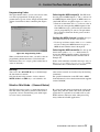
D00835000A
DAW Control Surface / FireWire Audio-MIDI Interface
OWNER’S MANUAL
The following marking is located on the bottom of the unit:
Ü
ÿ
Ÿ
CAUTION: TO REDUCE THE RISK OF ELECTRIC SHOCK, DO NOT
REMOVE COVER (OR BACK). NO USER-SERVICEABLE PARTS
INSIDE. REFER SERVICING TO QUALIFIED SERVICE PERSONNEL.
The lightning flash with arrowhead symbol, within an equilateral triangle, is intended to alert
the user to the presence of uninsulated “dangerous voltage” within the product’s enclosure
that may be of sufficient magnitude to constitute a risk of electric shock to persons.
The exclamation point within an equilateral triangle is intended to alert the user to the presence of important operating and maintenance (servicing) instructions in the literature
accompanying the appliance.
This appliance has a serial number
located on the rear panel. Please record
the model number and serial number
and retain them for your records.
Model number
Serial number
WARNING: TO PREVENT FIRE OR SHOCK
HAZARD, DO NOT EXPOSE THIS
APPLIANCE TO RAIN OR MOISTURE.
Important Safety Precautions
For CANADA
This class A digital apparatus complies with Canadian
ICES-003.
Cet appareil numérique de la class A est conforme à la
norme NMB-003 du Canada
For the consumers in Europe
WARNING
This is a Class A product. In a domestic environment, this
product may cause radio interference in which case the user
may be required to take adequate measures.
Pour les utilisateurs en Europe
AVERTISSEMENT
Il s’agit d’un produit de Classe A. Dans un environnement
domestique, cet appareil peut provoquer des interférences
radio, dans ce cas l’utilisateur peut être amené à prendre
des mesures appropriées.
Für Kunden in Europa
Warnung
Dies ist eine Einrichtung, welche die Funk-Entstörung nach
Klasse A besitzt. Diese Einrichtung kann im Wohnbereich
Funkstörungen versursachen; in diesem Fall kann vom
Betrieber verlang werden, angemessene Maßnahmen
durchzuführen und dafür aufzukommen.
2
TASCAM FW-1082 Owner’s Manual
For U.S.A
TO THE USER
This equipment has been tested and found to
comply with the limits for a Class A digital device,
pursuant to Part 15 of the FCC Rules. These
limits are designed to provide reasonable
protection against harmful interference when the
equipment is operated in a commercial
environment. This equipment generates, uses,
and can radiate radio frequency energy and, if
not installed and used in accordance with the
instruction manual, may cause harmful
interference to radio communications.
Operation of this equipment in a residental area
is likely to cause harmful interference in which
case the user will be required to correct the
interference at his own expense.
CAUTION
Changes or modifications to this equipment not
expressly approved by TEAC CORPORATION
for compliance could void the user’s authority to
operate this equipment.
Important Safety Instructions
Read these instructions.
Keep these instructions.
Head all warnings.
Follow all instructions.
Do not use this apparatus near water.
Clean only with dry cloth.
Do not block any ventilation openings. Install in
accordance with the manufacturer’s instructions.
8 Do not install near any heat sources such as radiators, heat registers, stoves, or other apparatus
(including amplifiers) that produce heat.
9 Do not defeat the safety purpose of the polarized
or grounding-type plug. A polarized plug has two
blades with one wider than the other. Grounding
type plug has two blades and a third grounding
prong. The wide blade or the third prong are provided for your safety. If the provided plug does not
fit into your outlet, consult an electrician for
replacement of the obsolete outlet.
10 Protect the power cord from being walked on or
pinched, particularly at plugs, convenience receptacles, and the point where they exit from the
apparatus.
11 Only use attachments/accessories specified by the
manufacturer.
1
2
3
4
5
6
7
12 Use only with the cart, stand, tripod, bracket, or
table specified by the manufacturer or sold with
the apparatus. When a cart is used, use caution
when moving the cart/apparatus combination to
avoid injury from tip-over.
13 Unplug this apparatus during lightning storms or
when unused for long periods of time.
14 Refer all serving to qualified service personnel. Servicing is required when the apparatus has been
damaged in any way, such as power-supply cord or
plug is damaged, liquid has been spilled or objects
have fallen into the apparatus, the apparatus has
been exposed to rain or moisture, does not operate
normally, or has been dropped.
• Do not expose this apparatus to drips or splashes.
• Do not place any objects filled with liquids, such
as vases, on the apparatus.
• Do not install this apparatus in a confined space
such as a book case or similar unit.
• The apparatus draws nominal non-operating
power from the AC outlet with its POWER switch
in the off position.
TASCAM FW-1082 Owner’s Manual 3
Contents
1 – Introduction
Overview ...................................................... 7
Features ........................................................ 7
System Requirements .................................. 8
In The Box .................................................... 8
Nomenclature used in the manual ............. 8
Software application notes ........................ 9
Special notes for touch-sensitive faders .... 9
Copyright, etc. ............................................. 9
2 – Parts of the FW-1082
Front Panel ................................................. 10
Input section .......................................................... 10
TRIM controls ..............................................10
OL indicators ...............................................10
Signal indicators .........................................10
Channel controls ................................................... 11
REC indicators .............................................11
SEL keys ......................................................11
Channel SOLO keys ....................................11
Channel MUTE keys ...................................11
Channel Faders ...........................................11
REC key .......................................................11
MASTER fader .............................................11
MIDI I/O ..................................................................14
Monitoring and phones ........................................14
PHONES jack ...............................................14
MONITOR (BAL) Outputs L & R ..................14
POWER jack and switch .........................................15
3 – Functional Overview
Control Surface Modes ..............................16
Global Controls ...........................................16
MASTER FADER ..........................................16
CONTROL SURFACE MODE keys ................16
CONTROL PANEL key .................................16
“Hidden” global function ......................................16
Dedicated Computer Controls ...................16
Dedicated Modifier Keys ...........................17
Setting and checking clock rates ...............17
Expected Sample Rate ...............................17
4 – Control Surface Modes and Operation
Bank Switch Behavior ................................18
Computer Control Mode – (General
Notes) .......................................................18
Native Protocol ......................................................18
Mackie Emulation Protocol ...................................19
HUI Emulation Protocol .........................................19
Encoders and controls ........................................... 12
MIDI Control Mode – (General Notes) ......20
Encoders ......................................................12
Encoder mode keys and indicators ...........12
EQ band keys (with indicators) .................12
Programming the MIDI Control Messages ...........21
Programming Keys ................................................21
Monitoring and indicators .................................... 12
PHANTOM ...................................................12
FireWire .......................................................12
CLOCK .........................................................12
D IN ..............................................................12
MONITOR ....................................................12
PHONES .......................................................12
MIDI IN and OUT indicators .......................12
Mode controls ....................................................... 12
CONTROL PANEL key .................................12
COMPUTER & MIDI CTRL keys ...................12
MON MIX key .............................................12
SHIFT key ....................................................12
MONITOR/function keys ............................12
DAW transport controls ........................................ 13
Arrow (cursor) keys ....................................13
Dial and SHTL (shuttle) key/indicator .......13
BANK selection keys and indicators .........13
LOCATE keys, SET, IN and OUT keys .........13
Transport keys and indicators ...................13
Rear panel .................................................. 13
Selecting the MIDI output(s) .....................21
Setting the MIDI channel ...........................21
Setting the MIDI message type .................21
Selecting the MIDI controller or note .......22
Programming Encoders .........................................22
Selecting the MIDI output(s) .....................22
Setting the MIDI channel ...........................22
Selecting the MIDI controller ....................22
Programming Faders .............................................23
Selecting the MIDI output(s) .....................23
Setting the MIDI channel ...........................23
Selecting the MIDI controller ....................23
Banking ..................................................................23
Monitor Mix Mode – (General Notes) .......23
Audio I/O and the Monitor Mixer ........................24
Monitoring Setups .................................................24
F1 / COMPUTER key ...................................24
F2 / INPUTS .................................................24
F9 / BOTH ....................................................24
Making mixer settings ..........................................24
FireWire (IEEE.1394) ports .........................14
Controlling the monitoring levels .............24
Setting the pan positions ..........................24
Setting the master fader to 0 dB
(unity gain) ..............................................24
Setting a channel’s monitor level to 0 dB
(unity gain) ..............................................24
Setting all monitor mix levels to 0 dB (unity
gain) .........................................................25
Setting all mixer parameters to default
values .......................................................25
Adjusting the fader sensitivity ..................25
COAXIAL Digital audio I/O (IN and OUT) ............. 14
Setting Input levels ...............................................25
Line inputs and inserts .......................................... 14
LINE IN jacks ................................................14
INSERT 1 & 2 ...............................................14
GUITAR/LINE switch ...................................14
Mic inputs and phantom power switch .............. 14
MIC (1 through 4) .......................................14
PHANTOM (+48V) switch ...........................14
Foot switch jack (FOOT SW) ................................. 14
4 TASCAM FW-1082 Owner’s Manual
Contents
5 – Control Panel
Settings tab .................................................26
Control Protocol ......................................... 26
Clock Source ............................................... 26
Sample Rate ............................................... 26
Audio Latency ............................................ 26
Coax Output Source .................................. 26
Master Fader Affects ANLG L:R Gain ...... 26
OVR Threshold ........................................... 27
Compensate for Converter delays (WDM) 27
MIDI Programming tab ..............................27
Quick Start tab (Windows only) ................27
CoreAudio tab (OS X only) ........................28
10-input/4-output ...................................... 28
4-input/4-output ........................................ 28
2-input/2-output ........................................ 28
6 – Troubleshooting and Support
Contacting Us .............................................30
7 – Specifications
Analog I/O ...................................................31
Digital I/O ....................................................32
Misc. I/O ......................................................32
Overall System Specifications ...................32
Analog performance ..................................33
Physical, etc. specifications ........................33
Dimensional drawing .................................34
TASCAM FW-1082 Owner’s Manual 5
Table of Figures
1 –Introduction
Figure 1.1:IEEE.1394 4-pin and 6-pin connectors .................................. 7
2 –Parts of the FW-1082
Figure 2.1:Front panel features ........................................................... 10
Figure 2.2:Rear panel features ............................................................. 13
3 –Functional Overview
Figure 3.1:Mode selection keys ........................................................... 16
Figure 3.2:Clock keys and indicators ................................................... 17
4 –Control Surface Modes and Operation
Figure 4.1:BANK keys and indicators .................................................. 18
Figure 4.2:Selecting Native Mode protocol ........................................ 19
Figure 4.3:Selecting Mackie Control emulation protocol .................. 19
Figure 4.4:Selecting HUI emulation protocol ...................................... 20
Figure 4.5:MIDI programming setup ................................................... 21
Figure 4.6:Programming control surface keys .................................... 21
Figure 4.7:Programming encoders ...................................................... 22
Figure 4.8:Programming faders ........................................................... 23
Figure 4.9:Bank keys used in monitor mix mode ............................... 24
Figure 4.10:Monitor mix setup keys .................................................... 24
5 –Control Panel
Figure 5.1:Settings tab ......................................................................... 26
Figure 5.2:Quick Start tab .................................................................... 27
Figure 5.3:Core Audio tab for OS X ..................................................... 28
6 –Troubleshooting and Support
Table 6.1:Audio troubleshooting ........................................................ 29
Table 6.2:Control surface troubleshooting ......................................... 29
7 –Specifications
Figure 7.1:Dimensions of the FW-1082 ............................................... 34
6 TASCAM FW-1082 Owner’s Manual
1 – Introduction
Overview
Thank you for choosing the TASCAM FW-1082. We
have designed the FW-1082 to be an all-in-one solution for your computer-based digital audio workstation system. Its integrated design incorporates a highresolution professional multi-channel audio interface
and integrated zero-latency input monitor mixer, a 2
x 2 MIDI interface, and a highly programmable,
ergonomically designed control surface for your
audio software.
The FW-1082 is designed to be the nerve center of
your digital audio environment. Its versatile control
surface features nine touch-sensitive motorized faders, transport and multi-function controls for direct,
immediate communication between your audio software and you. Its full complement of analog mic and
line inputs and S/PDIF inputs and outputs provides a
high resolution, 24-bit audio front end for input and
output of your digital audio workstation. Its integrated free-standing mixer provides the connectivity
you need for your entire studio, and it connects to
your Windows™ or MacOS™ computer with a single
FireWire™ connection.
Please take some time to look through this owner’s
manual and familiarize yourself with the FW-1082’s
features and operation. We suggest you pay particular attention to the operational notes for your software application(s) of choice. You may also want to
refer to your software’s documentation in many
cases, for a clear understanding of how certain features are integrated. Your experience with the FW1082 will be greatly enhanced by a good working
knowledge of your audio software.
Features
The audio input section is fully 24-bit and can
accommodate sample rates of up to 96 kHz. It is
capable of inputting up to ten simultaneous channels
of audio (eight analog and two S/PDIF digital) to
your computer. It features eight analog inputs, four
with professional quality microphone preamps and
switchable phantom power, as well as eight line
inputs and two analog channel inserts. Digital inputs
are available in an S/PDIF coaxial configuration.
The FW-1082 comes with a high-quality 6-pin to 6pin interface cable. We strongly suggest you use this
cable, or one of equal quality, for optimum audio performance. We always recommend the use of a 6-pin
IEEE.1394 connector (not the 4-pin type) on your
computer.
The output section offers two balanced line level analog outputs. A stereo S/PDIF coaxial digital output is
also featured.
The FW-1082’s control surface is intuitively
designed to integrate with all major digital audio
workstation software. Its nine touch-sensitive faders
respond instantly to your commands and update just
as quickly. Its transport controls, shuttle wheel and
generous array of application-dedicated switches
puts deep control of your audio software at your fingertips.
The FW-1082 is supported under Windows XP and
Windows 2000, and MacOS X 10.2.8 (Jaguar) or
later. In addition, your computer must be fitted with a
6-pin IEEE.1394 (FireWire™) interface.
NOTE
Some manufacturers may use a different nomenclature
to refer to their FireWire™ connections, such as Sony’s
“i.LINK”, or simply “1394”.)
Figure 1.1: IEEE.1394 4-pin and 6-pin connectors
The FW-1082 is supplied with a 2 m (6-foot) cable. If
you wish to use a longer cable, the length should not
be more than 4.5 m (15 feet) and the cable should be
the best possible quality available to avoid data loss,
which results in audio dropouts.
TASCAM FW-1082 Owner’s Manual 7
1 – Introduction
NOTE
We strongly suggest that although a “daisy-chain” connection is provided, that the FW-1082 is the only unit
connected to the FireWire port.
Always perform all FireWire connections and disconnections with the power to both the FW-1082 and the computer turned off. If connections are made or broken
with power to the FW-1082 or computer turned on, this
may result in your computer crashing, or “freezing” and
possible loss of data.
When turning the power of the FW-1082 on and off
when it is connected to the computer, turn on the
power before launching the DAW software, and quit
the software before turning off the FW-1082.
System Requirements
The FW-1082 is supported under Windows XP and
Windows 2000. The FW-1082 is not supported under
Windows 98 or Windows ME.
must be running SP1 and then install the supplied
Hotfix. Windows XP SP2 includes the Hotfix, so
there is no need to install it separately.
In the case of Windows 2000, you must be running
SP3 or SP4 and then install the supplied Hotfix. Windows 2000 SP5 includes the Hotfix, so there is no
need to install it separately. For Windows XP, you
On the Mac, the FW-1082 is supported under Mac
OS X version 10.2.8 or later. Earlier versions of Macintosh operating systems are not supported.
In The Box
The FW-1082’s box contains the items listed below.
When opening the package please be certain all the
items listed are included. If any items are missing,
please consult your TASCAM dealer.
• FW-1082
• AC power adapter (PS-1225B) and cable
• IEEE 1394 6-pin to 6-pin cable
• A CD-ROM containing the driver and utility software and documentation for the FW-1082 (Windows and Mac compatible).
• A second CD-ROM containing the Cubase LE
application.
• This manual
• The Setup Guide
• Warranty card.
Nomenclature used in the manual
Within this manual, the following typographic conventions are used:
• The name of a control or connector on the unit is
written in the following way: LINE/MIC.
• The name of a control or connector on another unit
is written in the following way: AUX IN.
• When referring to the screen display of the host
computer, we refer to any prompts, messages, etc.
in the following typeface: Press any key to
continue.
• If you have to type something into the computer,
we write it this way: FILENAME.EXT.
8 TASCAM FW-1082 Owner’s Manual
• The names of keys to be pressed on the computer
keyboard are written in this typeface with square
brackets enclosing them [F1].
• Keys that are to be pressed together are joined by a
+ symbol, so that [Ctrl]+[F1] means “press and
hold the Control key and press the F1 key”.
• Whenever we refer to the software application to
control and set up the FW-1082, we refer to it as
the “Control Panel” or the “software Control
Panel”.
• There are three control surface modes. These are
written in this manual as follows, to match the
labels of the respective mode keys: COMPUTER
(DAW control, etc.), MIDI CTRL (MIDI control) and
MON MIX (monitor mixer).
1 – Introduction
Software application notes
Since much of the FW-1082’s operation pertains
directly to your DAW software, TASCAM has prepared a series of application notes on using the FW1082 with a number of different DAW programs.
These Application Notes are included on the FW1082 CD-ROM, and are available online in PDF format on the TASCAM Web site.
To read them, you will need an application capable of
displaying PDF files, such as the Adobe Acrobat
Reader (version 4 or above), available for free download from the Adobe Web site at www.adobe.com.
Since software applications and operating systems
often evolve and develop after their initial release, we
suggest you check the TASCAM site regularly for
updated information. It’s also a good idea to check
your software manufacturer’s Web site regularly, for
information and version updates.
Special notes for touch-sensitive faders
The usual rules regarding precision electronic equipment naturally apply to the FW-1082. In addition,
note the following that apply to the touch-sensitive
faders:
The faders need a human finger to operate their
touch-sensitivity. Do not use a pencil, ruler, etc. to
operate them. Even using your fingernails may not
activate the touch-sensitivity.
The humidity and temperature of your environment
affects the touch-sensitivity of the faders. Under normal working conditions you should experience no
issues. However, extremes of temperature and/or
humidity may sometimes cause operational problems.
Copyright, etc.
Windows, Windows XP, and Windows 2000 are
trademarks of Microsoft Corporation.
HUI and Mackie CONTROL are trademarks of
LOUD Technologies Inc.
Macintosh, MacOS, MacOS X and FireWire™ are
trademarks of Apple Computer.
All other trademarks are the property of their respective holders.
i.LINK is a trademark of Sony Corporation.
TASCAM FW-1082 Owner’s Manual 9
2 – Parts of the FW-1082
Front Panel
The FW-1082 front panel may be conveniently
grouped into logical areas as shown in Figure 2.1.
Note that the functions of some of these controls may
change as the control mode changes.
Input section
See “Control Surface Modes” on page 16 for details
of these different modes and how to set them:
Encoders and
d
controls
Monitoring
and indicators
Mode
controls
Channel controls
DAW transport
controls
Figure 2.1: Front panel features
Input section
The analog input section of the FW-1082.
TRIM controls Analog level controls for the input
level of the mic (XLR) input 1 through 4, and line
inputs 1 through 8. Their function is the same regardless of the control surface mode selected. Note that
the best signal-to-noise ratios are achieved by maximizing the level of analog inputs at the A/D converters. For the mic and line inputs of the FW-1082, the
trim controls provide the means for optimizing these
levels.
OL indicators The OL indicators light to indicate
a signal peaking at –2.5dBFS or higher by default
10
TASCAM FW-1082 Owner’s Manual
(this level is adjustable between 0.0 dBFS and
5.0 dBFS, in 0.5 dB increments, using the FW-1082’s
software Control Panel). When one of these indicators lights, it indicates an overloaded input—reduce
the level of the input to the channel until the indicator
goes out.
Signal indicators The SIGNAL indicators light to
indicate the presence of an audio signal at the corresponding analog input.
These indicators and the OL indicators indicate signal levels to the eight analog inputs regardless of the
control surface mode selected.
2 – Parts of the FW-1082
Channel controls
These controls control the channels of the FW-1082.
The exact use depends on the mode currently
selected.
REC indicators In COMPUTER mode, depending
on the DAW application, these indicators light to
indicate the track record status (armed or recording).
In MON MIX mode, they are used to show pan status
(see “Monitor Mix Mode – (General Notes)” on
page 23).
SEL keys The SEL keys are used in COMPUTER
In MON MIX mode, the MUTE keys’ function is identical, but only affecting the monitor mix.
In MIDI CTRL mode, these keys send out specific controller commands.
Channel Faders In COMPUTER mode, the channel
faders send continuous controller information to
banks of eight channels in the host application’s software mixer. The current bank is selected using the
BANK keys.
mode to select the DAW channels if the faders are not
used for this purpose.
In MON MIX mode, the channel faders control the
monitor level of the audio inputs, as selected by the
BANK keys:
They are also used in this mode to set the record status of the channel, in conjunction with the REC key.
Bank 1: analog inputs
• Press and hold the REC key and press the SEL key
of a channel to arm or disarm it.
In MON MIX mode, pressing a channel’s SEL key
causes the REC indicators to show the selected channel’s pan position. Indicator 1 is lit with pan position
at full left, indicator 8 is lit at hard right, indicators 4
and 5 are lit together when panned center, etc.).
In MIDI CTRL mode, these keys send out specific controller commands.
Channel SOLO keys – In COMPUTER mode,
these keys solo their respective channels, while muting the audio on all other channels in the host application. Any number of channels can be soloed
simultaneously. Note that in COMPUTER mode, the
operation of the solo function is dictated by the host
application. For more information please refer to the
Application Notes for your DAW software application.
In MON MIX mode, the SOLO keys’ function is identical, but here they only affect the FW-1082’s built-in
monitor mixer.
In MIDI CTRL mode, these keys send out specific controller commands.
Channel MUTE keys In COMPUTER mode, these
keys mute the audio of the selected channel. Any
number of channels can be muted simultaneously.
Bank 2: S/PDIF inputs—channels 1 and 2 only.
Channels 3-8 are inactive.
NOTE
The faders do not affect the level of the signal sent to
the host computer.
In MIDI CTRL mode, the channel faders send out continuous MIDI controller commands.
REC key In COMPUTER mode, press and hold this
key and press a channel’s SEL key to arm or un-arm
a DAW track for recording. The channel’s REC indicator will light or flash, depending on the DAW
application. Consult the Application Notes for
details.
MASTER fader The MASTER fader is a global
control, functioning in the same manner regardless of
the selected control mode. Movements of the master
fader always simultaneously affect the host computer, the MIDI control surface and the monitor
mixer. There is always one and only one master fader
for the entire system.
Additionally, the MASTER fader can control the level
of the analog outputs. A setting in the FW-1082 Control Panel determines whether output directed to the
analog L-R is passed through to the outputs at unity
gain, or whether the MASTER Fader gain is applied
to the analog output signals.
• Refer to “Master Fader Affects ANLG L:R Gain”
on page 26 for details.
TASCAM FW-1082 Owner’s Manual 11
2 – Parts of the FW-1082
Encoders and controls
Encoders The four encoders are used in COMPUTER
mode to make EQ settings, adjust aux send levels,
etc.
Up to four EQ bands, with gain, frequency and Q settings for each band, and eight aux send levels of the
selected DAW channel can be controlled, depending
on the DAW software. See the Application Notes for
details.
In MON MIX mode, the PAN encoder acts as a pan
control for the selected channel. The other encoders
have no function.
In MIDI CTRL mode, the encoders send out continuous
MIDI controller commands.
Encoder mode keys and indicators These
keys are used in COMPUTER mode to select the basic
function of the encoders: either as EQ and pan controllers (from the top, gain, frequency, Q and pan) for
the selected channel, as aux sends 1 through 4 for the
selected channel, or as aux sends 5 through 8 for the
selected channel. The indicators light to show the
selected encoder mode.
In the MIDI CTRL mode they send out MIDI
messages.
When pressed in MON MIX mode, the EQ/PAN key
selects the FW-1082 itself as the word sync source
for the system (INTERNAL) and the AUX 1–4 key
selects the digital input as the word sync source (D
IN).
EQ band keys (with indicators) In COMmode, when the EQ/PAN encoder mode is
active, these keys are used to select the EQ band
affected by the encoders.
PUTER
When used in MON MIX mode, they are used to select
the sampling frequency when the FW-1082 is used as
the word sync source for the system.
In the MIDI CTRL mode they send out MIDI
messages.
Monitoring and indicators
PHANTOM This indicator lights when phantom
D IN This indicator lights when a valid clock signal
power is switched on for the microphone jacks.
is received at the digital input.
WARNING
MONITOR This analog control affects the level of
the signal sent from the balanced 1/4" MONITOR
Microphones should not be connected to or disconnected from the FW-1082 with phantom power
switched on.
(BAL) outputs.
Unbalanced dynamic microphones should never be connected to phantom-powered connectors.
signal sent from the stereo PHONES jack.
FireWire This indicator lights when a valid
IEEE.1394 (FireWire) connection is made between
the FW-1082 and the host computer.
PHONES This analog control affects the level of the
MIDI IN and OUT indicators These light
momentarily when MIDI activity is detected on the
appropriate port(s). These indicators function independently of the control mode.
CLOCK This indicator lights when the internal clock
is locked to the selected sampling frequency.
Mode controls
CONTROL PANEL key Brings up the software
SHIFT key This key is used to modify the behavior
Control Panel on the host computer.
of other keys. See the Application Notes for details of
how this key works with your particular DAW.
COMPUTER & MIDI CTRL keys Select either
the COMPUTER control (DAW control) or MIDI controller mode (MIDI CTRL).
MON MIX key Selects the monitor mix mode.
What is monitored and mixed is decided by the keys
described below.
12 TASCAM FW-1082 Owner’s Manual
MONITOR/function keys In MON MIX mode,
these keys determine which signals are monitored
(the right hand key of this group is not actually a
selection key, but returns the master to unity gain).
2 – Parts of the FW-1082
In COMPUTER mode, they send messages to the DAW
application. The exact message and the interpretation
depend on the application. Also note that these keys
can be SHIFTed to provide another four function
keys.
In MIDI CTRL mode, they typically send MIDI messages.
DAW transport controls
These controls have no meaning in MON MIX mode
(except for the BANK keys). In MIDI CTRL mode, they
typically send MIDI messages.
In COMPUTER mode, the exact function of these keys
is determined by the DAW application. Typical uses
are described here.
Arrow (cursor) keys Cursor keys for navigation
In MON MIX mode, the keys are used to select, and the
first two indicators show, whether the incoming analog (ANLG) or digital inputs (D IN) signals are being
monitored.
In MIDI CTRL mode, they are used to shift through the
“banks” of MIDI controllers provided by the FW1082.
around the screen.
LOCATE keys, SET, IN and OUT keys Typi-
Dial and SHTL (shuttle) key/indicator Typi-
cally used to locate to preset location points, to set
location points, and to set the punch points within a
DAW application.
cally used as scrub wheel, or shuttle (with indicator
lit).
BANK selection keys and indicators In
computer mode, select different banks of eight channels. The indicators light to give an indication of the
currently-selected bank.
Transport keys and indicators Used to control and show the status of a DAW’s transport functions.
Rear panel
Monitoring and
phones
Line inputs and inserts
Power jack and
switch
MIDI I/O
Digital
audio I/O
IEEE.1394
(FireWire)
ports
Mic inputs and phantom
power switch
Foot switch
jack
Figure 2.2: Rear panel features
TASCAM FW-1082 Owner’s Manual 13
2 – Parts of the FW-1082
Line inputs and inserts
LINE IN jacks Balanced line level (+4 dBu) ¼"
TRS (tip = hot, ring = cold, sleeve = ground) analog
inputs. Inputs 1 through 4 are wired in parallel with
their associated mic inputs. Only connect a line
source or a microphone to these pairs of inputs. Do
not connect a line source and a microphone to the
same input pair at the same time.
INSERT 1 & 2 Individual channel inserts. These
are ¼" TRS (tip = send, ring = receive, sleeve =
ground) jacks which allow you to insert an external
processor, such as an analog compressor, into the sig-
nal chain for inputs 1 and 2 (mic or line). The insert
point is placed between the input (after the mic/line
trim) and the analog-to-digital converter. A standard
insert’Y’-cable with a TRS plug is required. Check
with your music retailer.
GUITAR/LINE switch Affects LINE IN 8 only.
When this is set to GUITAR, the input impedance
then matches that of an electric guitar or passive bass.
For all other instruments, leave this in the LINE position.
Mic inputs and phantom power switch
MIC (1 through 4) These XLR connectors (1 =
ground, 2 = hot, 3 = cold) are connected to high-quality internal microphone pre-amplifiers.
PHANTOM (+48V) switch Use this to switch
+48V phantom power to the microphone jacks.
These connectors are wired in parallel with the correspondingly-numbered LINE IN jacks. Only connect a
line source or a microphone to these pairs of inputs.
Do not connect a line source and a microphone to the
same input pair at the same time.
Microphones should not be connected to or disconnected from the FW-1082 with phantom power
switched on.
WARNING
Unbalanced dynamic microphones should never be connected to phantom-powered connectors.
Foot switch jack (FOOT SW)
Accommodates a standard momentary foot switch
through a ¼" jack.
FireWire (IEEE.1394) ports Use one of these
ports to connect the FW-1082 to the host computer,
providing audio, MIDI and control surface communication. Either port may be used to connect the FW1082 to your computer
COAXIAL Digital audio I/O (IN and OUT)
S/PDIF coaxial digital input and output using RCA
(pin) connectors.
You can configure these on the software Control
Panel to act as additional inputs and outputs.
MIDI I/O
Two MIDI IN and two MIDI OUT connectors allow
you to hook up MIDI controllers, etc. as well as
external tone generator modules, etc.
Monitoring and phones
PHONES jack Headphone level output from a ste-
MONITOR (BAL) Outputs L & R Two bal-
reo 1/4” jack.
anced +4 dBU line-level ouputs on ¼” TRS jacks (tip
= hot, ring = cold, sleeve = ground).
14 TASCAM FW-1082 Owner’s Manual
2 – Parts of the FW-1082
POWER jack and switch
Connect only the power adapter supplied with your
FW-1082 to this jack.
Make sure the switch is off when making the power
connection.
WARNING
The FW-1082 outputs produce a “thump” when the
power is turned on.
To avoid any damage to hearing or equipment, turn the
volume of the monitoring system down, or make sure it
is turned off, and do not wear headphones connected
to the FW-1082 when powering the unit up or down.
TASCAM FW-1082 Owner’s Manual 15
3 – Functional Overview
Control Surface Modes
The FW-1082 control surface is extremely versatile,
and can be used to control a computer application, to
control an audio input monitor mix, and to send
MIDI messages to external devices via its MIDI outputs or to soft synthesizers, etc. through its two virtual MIDI ports.
One and only one of these keys may be selected and
lit at one time. Pressing one of these keys activates its
mode and lights the key.
The FW-1082’s control surface is always in one of
three modes: computer control mode (COMPUTER),
MIDI controller mode (MIDI CTRL) or monitor mix
mode (MON MIX). Each mode has a dedicated illuminated key, labeled COMPUTER, MIDI CTRL, and
MON MIX, respectively.
Figure 3.1: Mode selection keys
For more information on Control Surface modes, you
should refer to section 4, “Control Surface Modes
and Operation”, and to the Application Notes for
your software.
Global Controls
Certain controls operate globally; that is, they function the same way regardless of which control surface mode is selected. These controls are:
MASTER FADER – Any movement of the master
fader is always communicated to the host computer,
the MIDI control surface and the monitor mixer.
There is always one, and only one master fader for
the entire system.
CONTROL SURFACE MODE keys – These
three keys are used to select the current control surface mode. This is their only function. Only one control surface mode (and hence only one key) can be
selected at a time.
CONTROL PANEL key – This key always opens
the FW-1082 control panel on the host computer,
assuming it is connected and powered on.
“Hidden” global function
The following function is not printed on the control
surface panel, but is available in all modes.
SHIFT+MIDI CTRL
Enters MIDI Programming mode if host computer is
attached.
Dedicated Computer Controls
Some surface controls are computer-dedicated; that
is, they always send a MIDI data signal to the host
computer (assuming it is connected), regardless of
which control surface mode is currently selected.
These controls are:
• Transport keys (STOP, PLAY, REW, F FWD,
RECORD)
16
TASCAM FW-1082 Owner’s Manual
• Dial and SHTL (shuttle) key
• Cursor keys
• m LOCATE ,, SET, IN and OUT keys
• SHIFT key
• CONTROL PANEL key
The footswitch jack also communicates with the host
computer at all times. If you have a footswitch device
3 – Functional Overview
connected to this jack, activating it will always send a
command to the host computer.
Note that in MIDI CTRL mode these controls also send
programmable MIDI messages to the FW-1082’s
physical and virtual MIDI outputs.
Dedicated Modifier Keys
There is a dedicated modifier key on the FW-1082’s
control surface: the SHIFT key. This key has no effect
when pressed alone.
However, you can press and hold it to modify the
functions of a number of other keys when pressed
together with it.
These functions are chiefly dictated by the host
application software.
In most DAW applications, pressing and holding the
REC key and then pressing a channel’s SEL key will
generally arm the selected track(s) for recording.
Setting and checking clock rates
The FW-1082’s audio clock rate and source can be
checked or changed directly from the control surface.
current clock settings. Note that these keys have no
meaning in MON MIX mode other than clock settings.
The software Control Panel can also be used to do
this as described in “Settings tab” on page 26.
WARNING
The FW-1082 outputs produce a “thump” when the
power is turned on. To avoid any damage to hearing or
equipment, turn the volume of the monitoring system
down, or make sure it is turned off, and do not wear
headphones connected to the FW-1082 when powering
the unit up or down.
1 Put the FW-1082 into MON MIX mode by pressing the MON MIX key which then lights.
2 Press one of the clock rate keys to select the
sampling frequency:
•
•
•
•
96kHz (EQ HI–AUX 1/5)
88.2kHz (EQ HI MID–AUX 2/6)
48kHz (EQ LO MID–AUX 3/7)
Figure 3.2: Clock keys and indicators
44.1 kHz (EQ LOW MID–AUX 4/8)
3 Press either of the clock source keys:
• INTERNAL (EQ/PAN) – Internal Clock
• D IN (AUX1–4) – S/PDIF Input
When the FW-1082 is in MON MIX mode, these rate
and source keys and indicators light to display the
Expected Sample Rate If the S/PDIF input is
selected as the clock source and it does not have a
usable clock signal, the CLOCK indicator flashes to
indicate a problem, and the unit switches to its own
internal clock and waits for a valid clock signal. If
the sample rate is off by 3% or more, the FW-1082
switches to the incoming clock, and the nearest sample rate indicator blinks slowly.
TASCAM FW-1082 Owner’s Manual 17
4 – Control Surface Modes and Operation
As mentioned in “Functional Overview” on page 16,
the FW-1082’s control surface functions in three different control modes: computer control mode, MIDI
controller mode or monitor mix mode. While all
three modes share certain global functions, each
mode is quite different in its functionality and focus.
Bank Switch Behavior Each mode has a dedicated illuminated key, labeled COMPUTER, MIDI
CTRL, and MON MIX, respectively. Only one of these
keys may be selected and illuminated at one time.
Pressing one of these keys activates its designated
mode and lights the key.
In COMPUTER mode, the host application interprets
the banking keypresses and sends bank indicator
information back to the FW-1082. Therefore, the
function of the BANK indicators is applicationspecific.
• For example, a control surface plug-in may use the
bank switches to navigate between 4 sets of 8 faders so that you can manage the settings of a 32input mixer defined within the software.
In MIDI CTRL mode there are always four banks of
user-defined messages. Refer to “MIDI Control
Mode – (General Notes)” on page 20, for more
details.
In MON MIX mode there are two banks which correspond to different groups of FW-1082 audio inputs.
Refer to section , “Monitor Mix Mode – (General
Notes)”, for more details.
Each control surface mode recalls its most recently
selected bank when you return to it. For example, if
you have bank 2 selected in MIDI CTRL mode, and
switch to COMPUTER control mode where bank 1 is
selected, when you next return to MIDI CTRL mode,
bank 2 will be selected.
Figure 4.1: BANK keys and indicators
Computer Control Mode – (General Notes)
As its name implies, the COMPUTER control mode is
designed to communicate with the host computer, to
control your Digital Audio Workstation (DAW)
application software. When the FW-1082 is in this
mode, fader and encoder movements and all keypresses are transmitted to the host computer and
interpreted by the host application software (with the
exception of certain global keys like control surface
mode controls).
In addition, the host computer can send information
back to the FW-1082 to update fader positions and
light LEDs.
In COMPUTER mode, the FW-1082 can communicate
with the host computer in a number of different protocols (e.g. Native Mode, Mackie Control Emulation
Mode, etc.). General details of each of these modes
can be found in the sections which follow. For more
specific details refer to the Application Notes for
your software.
For correct operation, it is important to use the control mode designed to work with your DAW, as
described in the Application Notes. We recommend
you check the TASCAM Web site for current information and support status.
Native Protocol
Native Protocol is the FW-1082’s default control surface mode. In this mode, the FW-1082’s controls
transmit MIDI messages as detailed in the documentation on the CD-ROM.
18
TASCAM FW-1082 Owner’s Manual
Select Native protocol when using the FW-1082 to
control applications with native support and a separately-installed software plug-in; these include Cakewalk SONAR, MOTU Digital Performer and others.
4 – Control Surface Modes and Operation
To set the FW-1082 to Native protocol:
1 Open the FW-1082 Control Panel
3 In the drop-down Control Protocol menu,
select FW-1082 NATIVE.
2 Select the Settings tab
Figure 4.2: Selecting Native Mode protocol
For more detailed information on specific implementation within the host application, please refer to the
Application Notes for your software of choice.
Mackie Emulation Protocol
The FW-1082 can be used to emulate the control
messages sent by the Mackie Control™.
3 In the drop-down Control Protocol list,
select Mackie Control Emulation.
When in Mackie Control Emulation mode, the audio
and MIDI functionality of the FW-1082 are
unchanged, but the MIDI messages transmitted and
recognized by most of the control surface are
changed to closely pattern those of the Mackie Control.
This enables you to use the FW-1082 with software
applications which may not yet directly support the
FW-1082’s Native Mode, but do support the Mackie
Control.
To set up FW-1082 to the Mackie Emulation
protocol:
1 Open the FW-1082 Control Panel
2 Select the Settings tab
Figure 4.3: Selecting Mackie Control emulation
protocol
For detailed information on how the FW-1082’s control surface maps to controls within specific applications, please refer to the Application Notes for the
corresponding application .
HUI Emulation Protocol
The FW-1082 can be used to emulate the control
messages sent by the Mackie HUI™ (Human User
Interface).
When in HUI emulation mode, the audio and MIDI
functionality of the FW-1082 are unchanged, but the
MIDI messages transmitted and recognized by most
of the control surface are changed to closely pattern
those of the Mackie HUI. This enables you to use the
FW-1082 with software applications which may not
yet directly support the FW-1082’s Native mode, but
do support the HUI.
To set up the FW-1082 in HUI emulation protocol:
1 Open the FW-1082 Control Panel
TASCAM FW-1082 Owner’s Manual 19
4 – Control Surface Modes and Operation
2 Select the Settings tab
3 In the drop-down Control Protocol menu,
select HUI Emulation.
For detailed information on how the FW-1082’s control surface maps to controls within specific applications, please refer to the Application Notes for the
corresponding application.
Figure 4.4: Selecting HUI emulation protocol
MIDI Control Mode – (General Notes)
In MIDI CTRL mode, the FW-1082’s keys, encoders
and faders can be used to control external MIDI
devices by transmitting MIDI messages to its two
physical MIDI outputs and two virtual MIDI outputs
(transmitted through the FireWire cable to the
computer).
In this mode there are four banks, which you can
switch between using the h BANK y keys. With
the exception of the master fader, each of the four
banks can represent a separate and independent layer
of channel faders, encoders and keys. The master
fader is global to all banks and all control surface
modes.
In this mode, most of the FW-1082’s surface controls
can be programmed to send out messages.
TIP
Pressing and holding the SHIFT key and turning an
encoder will result in fine control of the parameter
being controlled. Non-shifted encoders provide fast
coarse control of parameters.
The following keys cannot be programmed:
• CONTROL PANEL
• SHIFT
• REC
In addition, note that the eight channel strip controls
(FADER, MUTE, SOLO, and SEL) are all bankable;
that is, each of these controls is capable of sending
four separate control messages, depending on which
bank is selected with the BANK keys.
20 TASCAM FW-1082 Owner’s Manual
The FW-1082’s MIDI control messages are pre-programmed, as described in the documentation on the
CD-ROM. However, you can reprogram any or all of
the controls and customize them for your particular
MIDI setup.
• Reprogram them through the FW-1082 Control
Panel, under the MIDI Programming tab.
TIP
Press and hold the FW-1082’s SHIFT+F3 keys to reset
the MIDI surface programming assignments to the factory default settings and write them to memory. The
FW-1082 must not be in MIDI Programming mode when
you perform this reset.
NOTE
Some controls are dedicated computer controls, meaning that they always transmit a signal to the host computer, even in MIDI CTRL mode. These controls are:
• Transport keys (STOP, PLAY, REW, F FWD,
RECORD)
• Dial and SHTL (shuttle) key
• Cursor keys
• m LOCATE ,, SET, IN and OUT keys
• SHIFT
• CONTROL PANEL
Unless you are an experienced MIDI programmer, we
recommend you exercise caution in assigning MIDI
functions to these keys which could cause potential
operational conflicts.
4 – Control Surface Modes and Operation
Programming the MIDI Control Messages
Open the FW-1082’s Control Panel by pressing the
CONTROL PANEL key on the FW-1082.
Select the MIDI Programming tab. This tab has a single display window.
If your FW-1082 is not powered on and connected to
the computer, the window displays FW-1082 Not
Available. Once the FW-1082 is powered on and
connected, the display shows the screen shown in
Figure 4.5:
Note that this only works if the FW-1082 is connected to a host computer. The FW-1082’s Control
Panel opens to the MIDI Programming tab.
• You can leave the MIDI programming mode at any
time by pressing the MIDI CTRL key alone or
selecting any other control surface mode.
Once you have entered MIDI Programming mode,
the MIDI Programming tab window on the FW1082’s control panel displays the programming information for one of the MIDI control keys, encoders or
faders.
• Display the programming information for any control by activating it: press a key, move an encoder,
touch or move a fader, and that control’s programming information is displayed. Note that messages
are not actually sent in MIDI Programming mode,
to avoid unexpected behavior of peripheral equipment while programming
Changes that you make to the programmed MIDI
messages take effect immediately. Further, they are
remembered even when the FW-1082’s power is
turned off.
Figure 4.5: MIDI programming setup
• To enter MIDI programming mode, hold SHIFT
and press the MIDI CTRL key; the MIDI CTRL key
flashes.
TIP
Reset the MIDI controller assignments to their factory
defaults by pressing and holding SHIFT and pressing
F3. The FW-1082 must not be in MIDI Programming
mode when you perform this reset.
Programming Keys
If you press one of the keys used in the MIDI CTRL
surface mode, it will light up and the FW-1082’s
Control Panel shows a screen similar to Figure 4.6:
tual MIDI outputs which appear as MIDI sources in
your DAW, but have no physical port (VP1 and VP2).
• Check or un-check the four Port boxes to select or
de-select the corresponding MIDI output or outputs
for this key. MIDI messages generated by the key
that you are programming are sent to each port
whose box is checked. Uncheck all four ports to
make a key inactive.
Setting the MIDI channel All MIDI messages
from this key must be on the same channel.
• Use the up and down arrows of the Channel indicator box to change the MIDI channel or type in a
MIDI channel number from 1 through 16.
Setting the MIDI message type
Figure 4.6: Programming control surface keys
Selecting the MIDI output(s) The FW-1082
has two physical MIDI outputs (1 and 2) and two vir-
These MIDI control keys are capable of transmitting
one of three possible MIDI messages. The message
type is selected in the control panel:
TASCAM FW-1082 Owner’s Manual 21
4 – Control Surface Modes and Operation
Controller On/Off
Note On/Off
• A controller value of 127 is transmitted when the
key is pushed, and a value of 0 is transmitted when
it is released. You can program the controller number.
Toggled Controller On/Off
• A Note On message is transmitted when the key is
pushed, and a Note Off message is transmitted
when it is released. You can program the note number.
• A controller value of 127 is transmitted when the
key is pushed. Nothing is transmitted when it is
released. When the key is pushed again, a value of
0 is transmitted; again, nothing is transmitted when
it is released. You can program the controller number.
Selecting the MIDI controller or note Use
the up and down arrows of the Controller indicator
box to change the MIDI controller number. Alternatively, you can type in a MIDI controller number
from 0 through 127.
This field changes to Note if the Note On/Off option
is selected. Select a MIDI note number or type one
in.
Programming Encoders
The four encoders can be reprogrammed. To display
the programmed message for an encoder, just turn it
slightly. The Control Panel shows something like
Figure 4.7:
Selecting the MIDI output(s) The FW-1082
has two physical MIDI outputs (1 and 2) and two virtual MIDI outputs which appear as MIDI sources in
your DAW, but have no physical port (VP1 and VP2).
• Check or un-check the four Port boxes to select or
de-select the corresponding MIDI outputs for the
encoder. MIDI messages generated by the encoder
that you are programming are sent to each port
whose box is checked. Uncheck all four ports to
make a key inactive.
Setting the MIDI channel All MIDI messages
from this encoder must be on the same channel.
• Use the up and down arrows of the Channel indicator box to change the MIDI channel or type in a
MIDI channel number from 1 through 16.
Figure 4.7: Programming encoders
Selecting the MIDI controller Use the up and
down arrows of the Controller indicator box to
change the MIDI controller number. Alternatively,
you can type in a MIDI controller number from 0
through 127.
Encoders send continuous controller messages only,
so the Note On/Off and Toggled Controller
options on the FW-1082’s Control Panel are disabled.
22 TASCAM FW-1082 Owner’s Manual
4 – Control Surface Modes and Operation
Programming Faders
The eight channel faders, as well as the master fader,
can all be reprogrammed. To display the programmed message for a fader, simply touch the fader
and the Control Panel shows something like Figure
4.8:
Selecting the MIDI output(s) The FW-1082
has two physical MIDI outputs (1 and 2) and two virtual MIDI outputs which appear as MIDI sources in
your DAW, but have no physical port (VP1 and VP2).
• Check or un-check the four Port boxes to select or
de-select the corresponding MIDI outputs for the
fader. MIDI messages generated by the fader that
you are programming are sent to each port whose
box is checked. Uncheck all four ports to make a
key inactive.
Setting the MIDI channel All MIDI messages
from this fader must be on the same channel.
• Use the up and down arrows of the Channel indicator box to change the MIDI channel or type in a
MIDI channel number from 1 through 16.
Figure 4.8: Programming faders
When you touch the master fader, you will see that its
programming information does not include bank
information since it is a single, global control that is
active in all banks.)
Selecting the MIDI controller Use the up and
down arrows of the Controller indicator box to
change the MIDI controller number. Alternatively,
you can type in a MIDI controller number from 0
through 127.
Faders send continuous controller messages only, so
the Note On/Off and Toggled Controller options
on the FW-1082’s Control Panel are disabled.
Banking
You can use the h BANK y keys to shift through
the four banks of controls.
other surface controls are unaffected by the banking
commands.
Only the channel strip controls—faders, channel
MUTE, SOLO and SEL keys—are bankable. All
For specific information on the FW-1082’s MIDI
Control Protocol, refer to the documentation supplied
on the CD-ROM.
Monitor Mix Mode – (General Notes)
The FW-1082 can be used as a stand-alone mixer in
MON MIX mode. The primary benefit of this mode is
to provide a means of monitoring your audio inputs
in a zero-latency environment.
By using MON MIX mode to monitor the audio at the
inputs along with the audio return from your DAW
application, it is possible to overdub tracks to your
DAW software with none of the audio processing
delays inherent in DAW applications.
TASCAM FW-1082 Owner’s Manual 23
4 – Control Surface Modes and Operation
Audio I/O and the Monitor Mixer
In MON MIX mode, there are two banks which correspond to the two types of audio inputs available on
the FW-1082.
The banks are labeled above the BANK switches as
follows:
• ANLG – Controls the monitor levels of the eight
analog inputs
• D IN – Controls the monitor levels of the S/PDIF
digital inputs. In this bank, channels 3-8 are
inactive.
Figure 4.9: Bank keys used in monitor mix mode
Monitoring Setups
When the FW-1082 is in MON MIX mode, the F1, F2
and F3 keys determine what source is monitored.
useful for setting up live inputs or tracking into your
DAW.
This is useful for isolating the audio coming from
your DAW or from external inputs. When the MON
MIX key is pressed, the F1, F2 or F3 key lights to
show the currently selected input source:
F9 / BOTH The audio signals from the host DAW
and the FW-1082’s inputs are monitored.
• The default setting is BOTH.
NOTE
Figure 4.10: Monitor mix setup keys
F1 / COMPUTER key Only the audio from the
host computer is monitored. This can be useful if
you’re doing a mixdown of your DAW tracks and
want to mute the monitor mixer without losing its
settings.
F2 / INPUTS Only the audio from the FW-1082’s
analog and S/PDIF inputs is monitored. This can be
It is important to understand that in MON MIX mode, the
FW-1082’s channel faders and pans are controlling the
monitor levels of the FW-1082’s input sources. While
you will still hear the audio returns from your DAW ,
and the FW-1082’s transport controls will still control
your DAW’s transports, moving the faders has no effect
on your DAW’s internal (software) mixer.
Another important point to note is that, in MON MIX
mode, the faders do not affect the levels the inputs sent
to your DAW. The levels to the DAW inputs from analog
inputs 1 through 8 (Bank 1) are controlled solely by
their respective TRIM pots. The two digital inputs (Bank
2) are passed to your DAW application at unity gain;
their level must be regulated at the digital source.
Making mixer settings
Once the monitor setup has been made, it is possible
to use the mixer to set the levels and pan position.
indicators 4 and 5 lit together mean that the channel
is panned to the center position.
Controlling the monitoring levels The fad-
• To set the position of a channel, press its SEL key,
and use the PAN encoder to set the position of the
channel in the mix. The SEL and REC indicators
go out soon after the SEL key is pressed.
ers control the monitor level of the inputs. Analog
inputs are controlled by bank 1, and digital S/PDIF
inputs by banks 2.
Setting the pan positions The REC indicators show the pan position of the monitored inputs
when you press the SEL key of the channel. REC 1 lit
alone means that the channel is panned hard left, and
REC 8 lit alone means it is panned hard right. REC
24 TASCAM FW-1082 Owner’s Manual
Setting the master fader to 0 dB (unity
gain) Press the F4 / MAST 0dB key.
Setting a channel’s monitor level to 0 dB
(unity gain) Hold SHIFT and press the channel
SEL key.
4 – Control Surface Modes and Operation
Setting all monitor mix levels to 0 dB
(unity gain) Press and hold the SHIFT key and
Adjusting the fader sensitivity This adjusts
then press the F4 / MAST 0dB key.
• Press and hold the SHIFT key and adjust the sensitivity with the EQ GAIN encoder.
• The REC and SEL indicators are used to show the
level of sensitivity (further to the left indicating less
sensitivity, and further right indicating more
sensitivity).
Setting all mixer parameters to default
values Press and hold the SHIFT key and then press
the F3 key.
the touch sensitivity of all faders.
Setting Input levels
As previously stated, the MON MIX mode can be very
useful for recording live tracks into a DAW application. Here’s a typical scenario for recording and overdubbing using MON MIX mode:
• Connect your analog and/or digital source(s) to the
FW-1082’s inputs.
• In COMPUTER control mode, arm your DAW tracks
for recording and meter the input level to those
tracks using the DAW’s level meters.
• Select MON MIX to access the monitor mixer control surface mode.
• Press the F2 INPUTS key to monitor the inputs
without hearing your existing DAW tracks.
• Solo an input channel by pressing that channel’s
SOLO key.
• Adjust the channel’s TRIM pot (if it is an analog
input) or the digital source (if it is a digital input)
until the input meter in your DAW shows a level
that is hot, but not clipping.
• Repeat this procedure for all active input channels.
Once you’re done setting up levels, you can return to
COMPUTER control mode and begin recording.
TASCAM FW-1082 Owner’s Manual 25
5 – Control Panel
The FW-1082’s Control Panel is where you can display and adjust settings which determine how the
FW-1082 communicates with your computer and
other external devices. To open the Control Panel,
press the CONTROL PANEL shortcut key on the FW1082’s control surface.
You can also open the Control Panel in Windows by
clicking on Start – Control Panel and selecting
the FW-1082 Control Panel icon. Under OS X, the
FW-1082 Manager can be found in Applications.
There are three tabs on the Control Panel: Settings,
MIDI Programming and Quick Start.
Settings tab
This is where you make the basic settings to configure the FW-1082.
Audio Latency This setting is for selecting the
buffer size of the FW-1082’s audio performance. The
FW-1082’s driver temporarily stores input and output
audio samples in buffers. Larger buffer sizes will produce higher latencies but will result in greater system
stability, and protection against other system activities causing clicks, pops and other audio artifacts.
NOTE
Note that if you are using the FW-1082’s MON MIX mode
to monitor your inputs, you will already have zerolatency monitoring. In this case, we recommend setting
the buffer size to 1024 or 2048 for maximum system stability.
Figure 5.1: Settings tab
Control Protocol This is where you select how
the FW-1082’s MIDI commands are interpreted by
the host software application. You can choose
between the FW-1082’s Native Protocol, Mackie
Control™ emulation protocol, or Mackie HUI™
emulation protocol and others.
Coax Output Source This setting determines
whether the coaxial digital output mirrors the FW1082’s analog monitor outputs (Analog L-R) or
whether it is independent of them, providing another
pair of outputs (SPDIF 1-2).
TIP
By using the S/PDIF outputs sourced from Analog L-R,
you can use the MONITOR control knob with speakers
with digital inputs.
Clock Source This is where you can select the dig-
Master Fader Affects ANLG L:R Gain The
ital clock source. It duplicates the clock selection
functions made on the control surface.
Master Fader Affects ANLG L:R Gain switch
determines whether the computer generated audio
sent to the analog outputs will be affected by the
master fader of the FW-1082.
Changes made on the FW-1082’s control surface are
immediately reflected in this window. For more
information on this function, refer to “Setting and
checking clock rates” on page 17.
Sample Rate This is where you select the
expected sample rate to the FW-1082’s digital input
and the internal sampling frequency. It duplicates the
control surface settings.
Changes made on the FW-1082’s control surface are
immediately reflected in this window. For more
information on this function, refer to “Setting and
checking clock rates” on page 17.
26
TASCAM FW-1082 Owner’s Manual
The default setting is OFF.
• Turn this switch on when the DAW application
you're using doesn't process "Master Fader" MIDI
messages originating from the FW-1082 surface. In
this case, the FW-1082's internal mixer will change
the gain of the analog outputs according to the setting of the master fader.
• Leave this switch off when your DAW application
responds to the "Master Fader" MIDI message by
changing the gain of the analog outputs using the
host processor.
5 – Control Panel
NOTE
It’s important that you do not leave this switch in the on
position if your DAW application does in fact alter the
gain of the audio signal in response to Master fader
messages from the FW-1082. In this situation, Master
fader gain would be applied twice - once in the host
application, and once by the FW-1082's internal mixer.
OVR Threshold This setting determines the level
at which the FW-1082’s meters register an “over,” or
clipping level. It can be varied between 0.0 and –5.0
dBFS, in .5 dBFS increments.
Compensate for Converter delays
(WDM) This setting (Windows only) allows WDM
drivers to compensate for converter delays.
MIDI Programming tab
This tab is used to program the FW-1082’s control
surface in MIDI CTRL mode. For detailed information
on using this function, please refer to “MIDI Control
Mode – (General Notes)” on page 20.
Quick Start tab (Windows only)
This allows you to specify a set of channels which
will always stream when using WDM/KS Driver
Mode in Sonar.
This, for example, speeds up the start of a playback
or record operation in Sonar, especially when there
are a lot of channels enabled. If there is a hesitation
after pressing PLAY or RECORD before the operation begins, try enabling this feature.
To use it, check the channels that you will be using in
your WDM audio app. When the channels selected in
the Quick Start tab match the channels actually
used by your application, the FW-1082 will not have
to re-sync when the application begins to use those
channels. This has shown to be much faster, and less
prone to produce an “audio engine stop” message.
Figure 5.2: Quick Start tab
TASCAM FW-1082 Owner’s Manual 27
5 – Control Panel
CoreAudio tab (OS X only)
In OS X, you can specify how the FW-1082 should
appear to the operating system:
4-input/4-output Select either the first four analog input channels (with the integrated mic pre-amps)
or the first two analog channels and the S/PDIF input
channels as inputs.
The outputs are the analog monitor outputs and the
digital S/PDIF digital output pair.
2-input/2-output Select a pair (1-2, 3-4 etc.) of
analog inputs or the digital S/PDIF inputs as the
input pair.
Select either the analog outputs, or the S/PDIF digital
outputs as the output pair.
TIP
Figure 5.3: Core Audio tab for OS X
The options available are as follows:
10-input/4-output All analog input channels are
used, and the analog monitor outputs are enabled.
The S/PDIF input channels become channels 9 and
10, and the S/PDIF output channels become two
additional output channels.
28 TASCAM FW-1082 Owner’s Manual
In order to optimize the load on your CPU, you should
configure the FW-1082 for your situation. If you are
making a live stereo recording using the FW-1082, there
is little point in configuring a 10-in/4-out device, for
example.
6 – Troubleshooting and Support
The FW-1082 is a complex device with a number of
inter-related components. If you experience problems
with your FW-1082, here are a few suggestions to
check first:
Table 6.1: Audio troubleshooting
Do you have a valid audio signal appearing at the FW-1082's
output buss? Check your output connections and monitoring
system.
Do you have the correct monitor source selected?
I hear no
sound.
If your audio source is an analog
input
Is the channel trim pot adjusted correctly?
If your audio source is a condenser
microphone
Do you have phantom power enabled?
Do you have a valid digital source connected?
If your audio source is a digital input
Are the correct clock settings selected?
If your audio source is your DAW
application
Do you have the correct outputs selected within the host
application?
If you're running Windows 2000 or
Windows XP
Does the FW-1082 appear as an audio device in Device Manager?
Id the Device Manager free of yellow exclamation marks?
My audio is distorted.
Is your input level too hot (OL indicators lighting)?
Do you have the correct clock source selected?
My audio has clicks and pops
Is the latency set too low?
Table 6.2: Control surface troubleshooting
Is the FireWire indicator lit, to indicate a valid connection?
Does the FW-1082 appear as a MIDI device in your DAW?
Is your DAW application correctly configured for an external
controller?
No Control Surface Response
Do you have the MIDI I/O ports set to “FW-1082 Control” on
MIDI input and output?
Is the FW-1082 control Port enabled in your DAW?
If you are running in Native Protocol, do you have the appropriate
plugin (SONAR, Digital Performer, etc.) installed in the correct
folder?
If you see no response to fader movements, do you have the
correct fader bank selected and visible on screen?
Incorrect Surface Response
If you are running in Mackie Control Emulation or Mackie HUI
Emulation protocol, do you have the correct controller selected in
your DAW application?
Do you have the correct control surface protocol selected in the
FW-1082’s Control Panel?
TASCAM FW-1082 Owner’s Manual 29
6 – Troubleshooting and Support
Contacting Us
In the event of any problems with your FW-1082,
please contact your dealer or your local TEAC/
TASCAM distributor.
30 TASCAM FW-1082 Owner’s Manual
Contact information may be found at the back of this
manual, or on the TASCAM Web site.
7 – Specifications
Analog I/O
MIC input 1-4 (Balanced)
Connector:
Input impedance
Adjustable Input range
Maximum gain
Phantom power
3-pin XLR jack x 4 (1: GND, 2: Hot, 3: Cold)
2.2k Ω
–56dBu (TRIM max) to –2 dBu (TRIM min)
+54 dB
Switchable +48V
LINE input 1-8 (Balanced)
Connector
Input impedance
Adjustable input range
Adjustable input range
Maximum gain
1/4 inch TRS jack x 8
10k Ω at LINE/MIC
500 kΩ at GUITAR (LINE Input: 8 switchable)
(channels 1–4) –42 dBu (TRIM max) to +12 dBu (TRIM min.)
(channels 5–8) –43 dBu (TRIM max) to +4 dBu (TRIM min.)
+54 dB (channels 1–4), +46 dB (channels 5–8)
INSERT 1-2 (Unbalanced)
Connector
1/4 inch TRS jack with tip SW x 2(T=SEND, R=RETURN, S=GND)
Send
Impedance
Normal level
Maximum level
100 Ω
-2 dBu
+14 dBu
Return
Impedance
Normal level
Maximum level
10k Ω
-2 dBu
+14 dBu
Analog MONITOR (BAL) output
Connector
Output impedance
Nominal output level
Maximum output level
1/4" balanced jack x 2
100 Ω
+4 dBu
+20 dBu
Phones output (Stereo)
Connector
Max output power
1/4 " stereo jack (T = L, R = R, S = GND) x 1
52 mW + 52 mW (32 Ω)
TASCAM FW-1082 Owner’s Manual 31
7 – Specifications
Digital I/O
Digital input (COAXIAL)
2-channel serial digital audio signal input terminal. In the case of Hi sampling, Hi-speed mode is supported.
Connector
RCA jack x 1
Input impedance
75 Ω
Format
IEC60958
Audio bit length
24-bit
Digital output (Coaxial)
2ch serial digital audio signal output terminal. In the case of Hi sampling, Hi-speed mode is supported.
Connector
RCA jack x 1
Output impedance
75 Ω
Format
IEC60958
Audio bit length
24-bit
Misc. I/O
MIDI input 1-2
MIDI input terminal
Connector
5-pin DIN connector – conforms to MIDI specifications x 2
FireWire‘ (IEEE.1394 digital interface)
Connector
Format
Transmit rate
IEEE.1394 connector x 2
IEEE.1394
400 Mbps
FOOT SW (foot switch)
Punch In/Out of DAW application
Connector:
Normally-open 1/4" TRS jack
Overall System Specifications
Sampling frequency
Internal clock
External clock
44.1kHz / 48.0kHz / 88.2kHz / 96.0kHz
Digital input
32 TASCAM FW-1082 Owner’s Manual
7 – Specifications
Analog performance
THD (Level+4dBu)
< 0.005 %
<0.01%
20 Hz - 20 kHz, LINE IN to INSERT SEND
1 kHz, LINE IN to MONITOR OUTPUT
Frequency response (@ nominal level)
20Hz – 20 kHz (normal FS)
20Hz – 40kHz (Hi FS)
20Hz - 20kHz (normal FS)
20Hz – 40kHz (Hi FS)
±1.0 dB, MIC/LINE IN to INSERT SEND
+0.5dB / –1.0 dB, MIC/LINE IN to INSERT SEND
±1.0 dB LINE IN to MONITOR OUTPUT
+0.5dB / –2.0 dB, LINE IN to MONITOR OUTPUT
Noise level (20Hz – 20kHz, TRIM max, 150 Ω)
< –128 dBu (EIN)
< –64dBu
MIC IN to INSERT SEND
LINE IN to MONITOR OUTPUT
Crosstalk (@ 1kHz)
> 80dB
MONITOR OUTPUT
Physical, etc. specifications
Power requirements
External power adapter AC input
Adapter output voltage
Power consumption
Applicable electromagnetic
environment
Peak inrush current
Dimensions (w x h x d)
Weight (excluding adapter)
Supplied accessories
100V AC, 50/60Hz
120V AC, 60Hz
230V AC, 50Hz
240V AC, 50Hz
12V, 2.5A
22W
E4
2.6 A
486 x 83 x 386 (mm) (19.1" x 3.25" x 15.2")
6.5 kg (14.3 lb)
AC adapter (PS-1225B) and AC cable
2m (6ft) IEEE.1394 6–6 cable
CD-ROM containing driver, utility software and documentation
CD-ROM containing Cubase LE
Owner’s Manual
Setup Guide
Warranty card
TASCAM FW-1082 Owner’s Manual 33
7 – Specifications
386 mm (15.2")
Dimensional drawing
83 mm (3.25")
486 mm (19.1")
Figure 7.1: Dimensions of the FW-1082
34 TASCAM FW-1082 Owner’s Manual
FW-1082
TEAC CORPORATION
Phone: (0422) 52-5082
3-7-3, Nakacho, Musashino-shi, Tokyo 180-8550, Japan
TEAC AMERICA, INC.
Phone: (323) 726-0303
7733 Telegraph Road, Montebello, California 90640
TEAC CANADA LTD.
Phone: 905-890-8008 Facsimile: 905-890-9888
5939 Wallace Street, Mississauga, Ontario L4Z 1Z8, Canada
TEAC MEXICO, S.A. De C.V
Phone: 5-851-5500
Campesinos No. 184, Colonia Granjes Esmeralda, Delegaacion Iztapalapa CP 09810, Mexico DF
TEAC UK LIMITED
Phone: 01923-819699
5 Marlin House, Croxley Business Park, Watford, Hertfordshire. WD1 8TE, U.K.
TEAC EUROPE GmbH
Phone: 0611-71580
Bahnstrasse 12, 65205 Wiesbaden-Erbenheim, Germany
TEAC FRANCE S. A.
Phone: 01.42.37.01.02
17 Rue Alexis-de-Tocqueville, CE 005 92182 Antony Cedex, France
TEAC AUSTRALIA PTY.,LTD. A.B.N. 80 005 408 462
Phone: (03) 9672-2400 Facsimile: (03)9672-2249
280 William Street, Port Melbourne, Victoria 3000, Australia
TEAC ITALIANA S.p.A.
Phone: 02-66010500
Via C. Cantù 11, 20092 Cinisello Balsamo, Milano, Italy
Printed In China