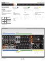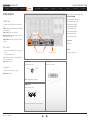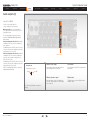
1
Software version TC1.0 NOVEMBER 2008 TANDBERG Codec C90 System Integrator Guide D14128.02—NOVEMBER 2008 1 Codec C90 Contents Contents Introduction System Integrator Guide Getting Started What’s in this guide? The top menu bar and the entries in the Table of Contents are all hyperlinks, just click on them to go to the topic. Interfaces About the API xConfiguration xCommand Table of Contents Introduction Cameras Appendices Contact us Audio inputs (I)............................................................................. 22 Microphone/Line In 1–8 (XLR)................................................. 22 HDMI In 3, 4............................................................................. 22 Line In 1–4 (RCA)..................................................................... 23 Disclaimer...................................................................................... 5 Audio outputs (I)........................................................................... 24 Line Out 5–6 (XLR).................................................................. 24 HDMI Out 1, 3.......................................................................... 24 Line Out 1–4 (RCA).................................................................. 25 Patent Information.......................................................................... 5 Audio Signal Levels tables........................................................... 26 Copyright Notice............................................................................ 5 Audio hardware information table................................................ 27 Safety Instructions......................................................................... 6 Volume control table.................................................................... 27 Environmental Issues..................................................................... 7 Network connectors.................................................................... 28 Ethernet interface..................................................................... 28 Intellectual Property Rights............................................................ 5 Trademark...................................................................................... 5 Getting started Assemble your system................................................................... 9 Using the Remote Control............................................................ 10 Turn on the system....................................................................... 12 Verify IP address settings............................................................. 12 If you need to set a static IP address........................................... 12 Add the system to the network.................................................... 13 Verify your settings....................................................................... 13 Time zone settings....................................................................... 13 About monitors............................................................................ 14 The main monitor..................................................................... 14 Dual monitors........................................................................... 14 Interfaces and sockets The front panel............................................................................. 16 Rear panel sockets overview....................................................... 17 The Video Input Matrix................................................................. 18 About the matrix...................................................................... 18 Configure the video inputs....................................................... 18 Administrator settings.............................................................. 18 API commands........................................................................ 18 Video inputs (I)............................................................................. 19 Component 1–2 (Y-Pr-Pb)........................................................ 19 HD-SDI 1–4.............................................................................. 19 Composite 5* / S-Video (YC) 5*............................................... 19 HDMI 1–4................................................................................. 20 DVI-I 3 and 5............................................................................ 20 Video outputs............................................................................... 21 HDMI 1 and 3........................................................................... 21 DVI-I 2 and 4............................................................................ 21 Composite 5............................................................................ 21 D14128.02—NOVEMBER 2008 xStatus COM port and Camera Control port............................................ 29 COM port................................................................................. 29 Camera Control port................................................................ 29 Power . ........................................................................................ 30 Power socket........................................................................... 30 Power switch........................................................................... 30 Chassis grounding................................................................... 30 Other connectors......................................................................... 31 USB......................................................................................... 31 GPIO........................................................................................ 31 T Link....................................................................................... 31 About the TANDBERG API TANDBERG API........................................................................... 33 Basic Principles....................................................................... 33 The TANDBERG API-Engine.................................................... 33 Structuring of Information.................................................... 33 Addressing Using XPath or TANDBERG SimplePath........... 34 Feedback............................................................................. 34 Connecting to the codec............................................................. 35 Accessing XACLI..................................................................... 35 Telnet/SSH login.................................................................. 35 Serial port login.................................................................... 35 Serial port configurations..................................................... 35 Hardware & Cabling (RS-232).................................................. 36 Troubleshooting (RS-232)........................................................ 36 Value types and formats.............................................................. 37 Root commands.......................................................................... 38 Main type of commands.............................................................. 39 Configuration type commands................................................. 39 Command type commands..................................................... 39 Status type commands............................................................ 39 Special commands.................................................................. 39 Feedback type command.................................................... 39 2 Codec C90 Contents Contents Introduction System Integrator Guide Getting Started Interfaces Preferences type command................................................. 39 About xConfiguration................................................................... 40 xConfiguration operations............................................................ 41 Return result parameters......................................................... 41 xConfiguration Help................................................................. 41 xConfiguration Read................................................................ 41 xConfiguration Write................................................................. 41 About xCommand........................................................................ 42 xCommand operations................................................................ 43 Return result parameters......................................................... 43 xCommand Help. .................................................................... 43 xCommand Write..................................................................... 43 About xStatus commands........................................................... 44 Query status information.......................................................... 45 About xHistory command............................................................ 46 About xFeedback......................................................................... 47 About xPreferences..................................................................... 48 TANDBERG XML API service....................................................... 49 xConfiguration type commands Description of the xConfiguration commands.............................. 51 The Audio settings................................................................... 51 The Camera settings................................................................ 53 The Conference settings.......................................................... 54 The Do not disturb setting....................................................... 55 The H323 Profile settings......................................................... 55 The Network settings............................................................... 56 The Network services settings................................................. 57 The Phone book settings......................................................... 59 The Provisioning settings......................................................... 59 The Serial port settings............................................................ 59 The SIP Profile settings............................................................ 60 The Standby settings............................................................... 60 The System unit settings.......................................................... 61 The Time zone setting.............................................................. 61 The Video settings................................................................... 61 The Experimental menu........................................................... 63 About the API xConfiguration xCommand The TString Send command.................................................... 72 The Far End Control commands.............................................. 73 The HTTP Feedback commands............................................. 74 The Key commands................................................................. 75 The Presentation commands................................................... 76 The Preset commands............................................................. 77 The SString Send command.................................................... 78 The Standby commands.......................................................... 78 The Video command................................................................ 79 The CamCtrlPip command...................................................... 79 The System Unit commands.................................................... 80 The Phone book commands.................................................... 81 The Experimental menu........................................................... 85 xStatus Cameras Appendices Contact us TANDBERG Remote Control TRC5............................................ 120 TANDBERG Remote Control TRC5 key map............................. 121 The PrecisionHD camera........................................................... 122 Connecting the camera......................................................... 122 CE Declaration for Codec C90................................................... 123 China RoHS table...................................................................... 124 TANDBERG Codec C90 dimensions......................................... 125 PrecisionHD 1080p camera dimensions.................................... 126 PrecisionHD camera dimensions............................................... 127 Technical specifications............................................................. 128 xStatus type commands xStatus commands...................................................................... 89 Examples of returned status information................................. 89 The Audio status...................................................................... 89 The Call status......................................................................... 90 The Camera status.................................................................. 91 The Conference status............................................................. 92 The Diagnostics Call status...................................................... 93 The H323 Gatekeeper status................................................... 97 The HTTPFeedback status...................................................... 97 The Media channels call status................................................ 97 The Network status.................................................................. 99 The SIP status........................................................................ 100 The System unit status.......................................................... 100 The Standby status................................................................ 103 The Video status.................................................................... 103 Cameras The PrecisionHD 1080p camera................................................ 106 Connecting the camera......................................................... 107 Best view—Face recognition...................................................... 108 Video output formats................................................................. 109 Cameras in daisy chain...............................................................110 Appendices xCommand type commands xCommands with parameters...................................................... 65 The Audio commands.............................................................. 65 The Boot command................................................................. 67 The Call commands................................................................. 67 The Call Log commands.......................................................... 68 The Camera commands.......................................................... 69 The Dial command................................................................... 71 The DTMF Send command...................................................... 72 D14128.02—NOVEMBER 2008 Software upgrade.......................................................................112 Upload certificates......................................................................113 XML files......................................................................................114 Log files.......................................................................................115 NTP Time Zone expressions.......................................................116 Supported RFCs in SIP...............................................................119 Current RFCs and drafts supported in SIP.............................119 Media capabilities supported in SIP........................................119 3 Codec C90 Introduction Introduction Contents System Integrator Guide Getting Started Interfaces About the API xConfiguration xCommand xStatus Cameras Appendices Contact us Chapter 1 Introduction Thank you for choosing TANDBERG! Your TANDBERG Codec C90 has been designed to give you many years of safe, reliable operation. In this chapter... Intellectual property rights Trademark Copyright How to read this document Disclaimer You will find that some places information has been copied from other chapters (but adapted, when needed) to let you have all the relevant information there and then. This helps eliminating the need to read through long sections before you can even think of getting started. Patent information Safety instructions Environmental issues Our main objective with this user guide is to address your goals and needs. Please let us know how well we succeeded! We recommend you visit the TANDBERG web site regularly for updated versions of the manual. Go to: http://www.tandberg.com/docs D14128.02—NOVEMBER 2008 4 Codec C90 Contents Introduction Introduction System Integrator Guide Getting Started Interfaces About the API xConfiguration xCommand xStatus Cameras Appendices Contact us Intellectual Property Rights Disclaimer Patent Information This System Integrator Guide and the Products to which it relates contain information that is proprietary to TANDBERG and its licensors. Information regarding the Products is found on the page entitled License Agreements and Patent Information. The specifications for the Products and the information in this document are subject to change at any time, without notice, by TANDBERG. The products described in this manual are covered by one or more of the following patents: US6,584,077 US5,838,664 US5,600,646 Every effort has been made to supply complete and accurate information in this System Integrator Guide, however, TANDBERG assumes no responsibility or liability for any errors or inaccuracies that may appear in this document. US5,003,532 US5,768,263 US5,991,277 US7,034,860 US7,010,119 EP01953201 US6.731.334 GB1338127 This System Integrator Guide may be reproduced in its entirety, including all copyright and intellectual property notices, in limited quantities in connection with the use of the Products. Except for the limited exception set forth in the previous sentence, no part of this System Integrator Guide may be reproduced, stored in a retrieval system, or transmitted, in any form, or by any means, electronically, mechanically, by photocopying, or otherwise, without the prior written permission of TANDBERG. Requests for such permission should be addressed to [email protected]. Trademark TANDBERG® is a registered trademark belonging to Tandberg ASA. Other trademarks used in this document are the property of their respective holders. COPYRIGHT © 2008, TANDBERG All rights reserved. Philip Pedersens vei 20 1366 Lysaker, Norway INTELLECTUAL PROPERTY RIGHTS The Products that are covered by this System Integrator Guide are protected under copyright, patent, and other intellectual property rights of various jurisdictions. Any applicable software licenses and any limited warranty are located in the License Information section in this TANDBERG Codec C90 System Integrator Guide. Other patents pending. This Product is Copyright Notice COPYRIGHT © 2008, TANDBERG All rights reserved. Please view list www.tandberg.com/tandberg_pm.jsp for an updated The product that is covered by this System Integrator Guide is protected under copyright, patent, and other intellectual property rights of various jurisdictions. This product is Copyright © 2008, Tandberg Telecom AS. All rights reserved. This product includes copyrighted software licensed from others. A document describing the copyright notices and the terms and conditions of use can be found at: http://www.tandberg.com/docs Navigate to User manuals > TANDBERG Codec C90 Copyright and License Information to download the pdf. Tel: +47 67 125 125 Fax: +47 67 125 234 E-mail: [email protected] D14128.02—NOVEMBER 2008 IMPORTANT: USE OF THIS PRODUCT IS SUBJECT IN ALL CASES TO THE COPYRIGHT RIGHTS AND THE TERMS AND CONDITIONS OF USE REFERRED TO ABOVE. USE OF THIS PRODUCT CONSTITUTES AGREEMENT TO SUCH TERMS AND CONDITIONS. 5 Codec C90 Contents Introduction Introduction System Integrator Guide Getting Started Safety Instructions For your protection please read these safety instructions completely before you connect the equipment to the power source. Carefully observe all warnings, precautions and instructions both on the apparatus and in these operating instructions. Retain this manual for future reference. Interfaces About the API xConfiguration Water and Moisture Do not operate the apparatus under or near water – for example near a bathtub, kitchen sink, or laundry tub, in a wet basement, near a swimming pool or in other areas with high humidity. • Never install jacks for communication cables in wet locations unless the jack is specifically designed for wet locations. xCommand xStatus The product may have hazardous voltage inside. • If the apparatus emits smoke or abnormal odor. • Never attempt to open this product, or any peripherals connected to the product, where this action requires a tool. • This product should always be powered from an earthed power outlet. Cleaning • In case any parts of the product has visual damage never attempt to connect main power, or any other power source, before consulting service personnel Do not block any of the ventilation openings of the apparatus. Never cover the slots and openings with a cloth or other material. Never install the apparatus near heat sources such as radiators, heat registers, stoves, or other apparatus (including amplifiers) that produce heat. Do not place the product in direct sunlight or close to a surface directly heated by the sun. Lightning Never use this apparatus, or connect/disconnect communication cables or power cables during lightning storms. Dust Do not operate the apparatus in areas with high concentration of dust. Vibration Do not operate the apparatus in areas with vibration or place it on an unstable surface. Contact us • If the cabinet has been damaged. • Never connect attached power supply cord to other products. Ventilation Appendices Power Connection and Hazardous Voltage • Do not touch the product with wet hands. Unplug the apparatus from communication lines, mains power-outlet or any power source before cleaning or polishing. Do not use liquid cleaners or aerosol cleaners. Use a lint-free cloth lightly moistened with water for cleaning the exterior of the apparatus. Cameras • The plug connecting the power cord to the product/power supply serves as the main disconnect device for this equipment. The power cord must always be easily accessible. • Route the power cord so as to avoid it being walked on or pinched by items placed upon or against it. Pay particular attention to the plugs, receptacles and the point where the cord exits from the apparatus. • If the apparatus seems to be overheated. • If the apparatus fails to operate in accordance with the operating instructions. Accessories Use only accessories specified by the manufacturer, or sold with the apparatus. Communication Lines Do not use communication equipment to report a gas leak in the vicinity of the leak. IMPORTANT! There should always be a distance of minimum 10 cm (0.33 ft) free space in the front of the codec. • Do not tug the power cord. • If the provided plug does not fit into your outlet, consult an electrician. Min. 10 cm • Never install cables, or any peripherals, without first unplugging the device from its power source. Servicing WARNING! • Do not attempt to service the apparatus yourself as opening or removing covers may expose you to dangerous voltages or other hazards, and will void the warranty. Refer all servicing to qualified service personnel. Make sure the Codec C90 never rest on the front panel. • Unplug the apparatus from its power source and refer servicing to qualified personnel under the following conditions: • If the power cord or plug is damaged or frayed. • If liquid has been spilled into the apparatus. • If objects have fallen into the apparatus. • If the apparatus has been exposed to rain or moisture • If the apparatus has been subjected to excessive shock by being dropped. D14128.02—NOVEMBER 2008 6 Codec C90 Contents Introduction Introduction System Integrator Guide Getting Started Environmental Issues Thank you for buying a product which contributes to a reduction in pollution, and thereby helps save the environment. Our products reduce the need for travel and transport and thereby reduce pollution. Our products have either none or few consumable parts (chemicals, toner, gas, paper). Interfaces About the API xConfiguration xCommand xStatus Cameras Appendices Contact us TANDBERG’s Environmental Policy European Environmental Directives Information for Recyclers Environmental stewardship is important to TANDBERG’s culture. As a global company with strong corporate values, TANDBERG is committed to following international environmental legislation and designing technologies that help companies, individuals and communities creatively address environmental challenges. As a manufacturer of electrical and electronic equipment TANDBERG is responsible for compliance with the requirements in the European Directives 2002/96/EC (WEEE - Waste Electrical and Electronic Equipment) and 2002/95/EC (RoHS). As part of compliance with the European WEEE Directive, TANDBERG provides recycling information on request for all types of new equipment put on the market in Europe after August 13th 2005. TANDBERG’s environmental objectives are to: • Develop products that reduce energy consumption, CO2 emissions, and traffic congestion • Provide products and services that improve quality of life for our customers • Produce products that can be recycled or disposed of safely at the end of product life • Comply with all relevant environmental legislation. Digital User Guides TANDBERG is pleased to announce that we have replaced the printed versions of our user guides with digital versions available on the TANDBERG web site: http://www.tandberg.com/docs. The environmental benefits of this are significant. The user guides can still be printed locally, whenever needed. The primary aim of the WEEE Directive and RoHS Directive is to reduce the impact of disposal of electrical and electronic equipment at end-of-life. The WEEE Directive aims to reduce the amount of waste electrical and electronic equipment sent for disposal to landfill or incineration by requiring producers to arrange for collection and recycling. The RoHS Directive bans the use of certain heavy metals and brominated flame retardants to reduce the environmental impact of WEEE which is in landfill or incinerated. Please contact TANDBERG and provide the following details for the product for which you would like to receive recycling information: • Model number of TANDBERG product • Your company’s name • Contact name • Address • Telephone number • E-mail. TANDBERG has implemented necessary process changes to comply with the European WEEE Directive (2002/96/EC) and the European RoHS Directive (2002/95/EC). Waste Handling In order to avoid the dissemination of hazardous substances in our environment and to diminish the pressure on natural resources, we encourage you to use the appropriate recycling systems in your area. Those systems will reuse or recycle most of the materials of your end of life equipment in a sound way. TANDBERG products put on the market after August 2005 are marked with a crossed-out wheelie bin symbol that invites you to use those take-back systems. Please contact your local supplier, the regional waste administration or visit our web page http:// www.tandberg.com/recycling if you need more information on the collection and recycling system in your area. D14128.02—NOVEMBER 2008 7 Codec C90 Contents Introduction System Integrator Guide Getting Started Getting Started Interfaces About the API xConfiguration xCommand xStatus Cameras Appendices Contact us Chapter 2 Getting started This chapter introduces you to the codec and gets you up and going. This guide has been divided into several chapters, all of which provide different information. You can access the chapters directly by clicking on the menu bar at the top of this page. In this chapter... Assemble your system Using the remote control Turn on the system Verify IP address settings Setting a static IP address Add the system to the network Verify your settings Time zone settings About monitors D14128.02—NOVEMBER 2008 8 Codec C90 Contents 1 Introduction System Integrator Guide Getting Started Getting Started Interfaces About the API xConfiguration xCommand xStatus Cameras Appendices Contact us Assemble your system The illustration shows you the basic setup when connecting your monitor, PC, camera, microphone, loudspeakers (if applicable), LAN and line voltage to your codec. OPTIONAL: Loudspeakers OPTIONAL: Audio from PC Video from PC LAN/ Ethernet Monitor (Audio from HDMI 1 or Line Out 1–2) Mains Power Cable Microphone OPTIONAL: You may connect a second camera. (extra camera not included). Extra camera will require separate power supply and control cabling. Consult the documentation supplied with the extra camera for details. Main camera: Video from PrecisionHD 1080p OPTIONAL: Dual monitor setup Connect the second monitor to HDMI 3 ! OPTIONAL: You may connect additional microphones Main camera: Camera Control to PrecisionHD 1080p Make sure the codec has been switched off and disconnected from the line voltage whenever connecting or disconnecting other equipment. D14128.02—NOVEMBER 2008 9 Codec C90 Contents Introduction System Integrator Guide Getting Started Getting Started Interfaces About the API xConfiguration xCommand xStatus Cameras Appendices Contact us Using the Remote Control The functions keys in the upper part of the remote control reflects the soft keys on screen. ARROW LEFT: Press the left arrow key to go one step back in the menu or to move to the left in a text field. ... and the middle part of the remote control is used to handle the video part of the call. 1 .@ 2 abc def 3 4 ghi 5 jkl mno 6 7 pqrs 8 tuv wxyz 9 0 abc/123 # ... while the lower part of the remote control resembles very much the keypad of a mobile phone Batteries 1 .@ MICROPHONE: Press the Microphone key to toggle the microphones on/off.4 ghi Make sure the remote control has working batteries (4 x AAA batteries). 7 pqrs 2 abc def ARROW RIGHT: Press the right arrow key to expand the selected menu item or to move to the right in a text field. 1 .@ OK/SELECT: Press the OK/ Select key to confirm your ordefselection. 3 abc 2choice 4 ghi 5 jkl mno 6 7 pqrs 8 tuv wxyz 9 0 abc/123 # 3PRESENTATION: Press the 5 jkl Presentation key to show/hide mno 6a presentation. 8 tuv wxyz 9 0 abc/123 # VOLUME: Press the + or – on the Volume key to adjust the codec volume. D14128.02—NOVEMBER 2008 ARROW UP/DOWN: Use the up and down arrow keys to navigate in the menu. FUNCTION KEYS: Each key reflects a soft key on screen and represents shortcuts and advanced functions. ZOOM: Press the + or – on the Zoom key to zoom the camera in and out. 1 .@ 2 abc def 3 4 ghi 5 jkl mno 6 7 pqrs 8 tuv wxyz 9 0 abc/123 # PHONE BOOK: Press the Phone Book key to display the local phone book. LAYOUT: Press the Layout key to display the layout menu, then select a view in the menu. 3 defthe 2 abc Press 1 . @ HOME: Home key to go back menu. 4 ghi to the 5 jklmainmno 6 7 pqrs 8 tuv wxyz 9 0 abc/123 # 10 Codec C90 Contents Introduction System Integrator Guide Getting Started Getting Started Using the Remote Control, cont... The functions keys in the upper part of the remote control reflects the soft keys on screen. Interfaces 1 .@ 2 abc def 3 5 jkl mno 6 7 pqrs 8 tuv wxyz 9 0 abc/123 # xConfiguration xCommand xStatus Cameras Appendices CALL KEY ALPHANUMERIC KEYPAD INITIATE CALL: Select a name from the Phone book or enter the name, number or URI and press the Call key to initiate the call. Use the keypad in the same way as you would use a cellular phone. Contact us SHORTCUT TO RECENT CALLS: Use the Call button as a shortcut to Recent Calls when the Call menu is not visible. END CALL, STANDBY: Press the End Call key to end a call, or when idle, press and hold the key to go into standby mode. ... and the middle part of the remote control is used to handle the video part of the call. 4 ghi About the API 1 .@ 2 abc def 3 1 .@ 2 abc def 3 4 ghi 5 jkl mno 6 7 pqrs 8 tuv wxyz 9 0 abc/123 # mnothe 4 ghiCLEAR: 5 jkl Press 6 Cancel ... while the lower part of the remote control resembles very much the keypad of a mobile phone key to remove characters 7 pqrsin a text 8 tuv field. wxyz 9 0 abc/123 0-9, a-z, period (.), @, space, *: Press a key repeatedly to toggle between the options displayed on each key. abc/123 #: Press the # key to toggle between lower case characters and numbers. # Waking up the system IR sensor range (DIP switch setting) Press any key on the remote control to wake up the system. The IR sensor has a short and long range. Open the battery cover and remove the batteries to set the DIP switch. • Short range (1 m): Move the DIP switch down • Long range: Move the DIP switch up. Press the HOME key to show the menu on screen The DIP switch 1 .@ 2 abc def 3 4 ghi 5 jkl mno 6 7 pqrs Touch the rubber line sensors along the sides to wake up the system D14128.02—NOVEMBER 2008 8 tuv wxyz 9 0 abc/123 # 11 Codec C90 Contents 1 Introduction System Integrator Guide Getting Started Getting Started Interfaces About the API Turn on the system • Turn on the codec and wait a few minutes for the system to start • Make sure the remote control has the batteries installed. • Press Home ( ) on the remote control to show the menu on screen • When you can see the menu on screen, proceed to Step 2. Show the menu: • Press Home ( 3 xConfiguration xCommand xStatus Cameras Appendices Contact us If you need to set a static IP address Go to IP Settings to set static IP addresses: 1. Navigate to Settings > Administrator Settings > IP Settings. 2. Set IP Assignment to Static. Press the left arrow key to go back one step 3. Enter the IP Address, Subnet Mask and Gateway address in the address fields. The sequence is shown below. 4. Press OK to save the changes, or Cancel to leave without saving. ) on the remote control to show the menu on screen 5. Press Home ( ) to exit. Navigate in the menu: • Use the arrow keys on the remote control to navigate up and down in the menus Confirm your choice: • To confirm your choice, press OK ( 2 ) on the remote control Verify IP address settings Go to System Information to verify the IP address: 1. Navigate to Settings > System Information 2. When the IP address is automatically assigned from a DHCP server, the Address of the codec is shown on the System Information page. 3. Press Home ( D14128.02—NOVEMBER 2008 ) to exit. 12 Codec C90 Contents 4 Introduction System Integrator Guide Getting Started Getting Started Interfaces About the API Add the system to the network Your service provider should have provided you with the information you need to get on-line. xConfiguration 5 xCommand xStatus Cameras Appendices Contact us Verify your settings We strongly recommend that you verify the settings by inspecting the System Information list. For H323 type of communication, this will include such things as system name, H323 alias, gatekeeper address, etc. For SIP type of communication, similar type of information will be supplied. You do this by accessing the System Information in the same way as you did when you verified you IP address setting. For networks administrated through TMS (TANDBERG Management Suite), your TMS administrator will be able to assist you when configuring. Go to System Information to verify the settings: 1. Navigate to Settings > System Information The H323 and SIP settings are configured from the Administrator Settings menu: 2. Verify the previous configurations. For example, if you successfully registered to a SIP server the Status will show Registered. If the registration failed the Status will show Not registered. Navigate to Settings > Administrator Settings > Advanced Settings. 3. Press Home ( • Expand the items in need of modification and enter the information supplied by your service provider. 6 ) to exit. Time zone settings Verify the date and time to see if the time zone settings need to be adjusted. The date and time is located in the upper right corner on screen. Go to Time settings to set the NTP (date and time) settings: 1. Navigate to Settings > Administrator Settings > Time > Zone 2. You may need to consult the NTP Time Zone expression list to find the exact expression. Go to the Appendices section and the NTP Time Zone expressions to see a complete overview. 3. Enter the time zone expression for where the system is located. The default value is Etc/UTC. NOTE: Spelling correctly is important when entering the NTP Time Zone expression 4. Press Save to save the changes, or Cancel to leave without saving. 5. Press Home ( D14128.02—NOVEMBER 2008 ) to exit. 13 Codec C90 Contents Introduction System Integrator Guide Getting Started Getting Started Interfaces About monitors About the API xConfiguration xCommand xStatus Cameras Appendices Contact us The video outputs at Codec C90 The main monitor The main monitor can be connected to the default video output HDMI 1 or one of the other outputs which are HDMI 3, DVI-I 2 or DVI-I 4. When connecting to HDMI 1 When you connect the main monitor to the default video output on Codec C90 the menu, icons and other information on screen (OSD on screen display) will show on this monitor. DVI-I 4 When connecting to DVI-I 2, DVI-I 4, HDMI 3 HDMI 3 (the default connector for the dual monitor) When connecting the main monitor to another video output, and no menu shows on screen, you must run a shortcut on the remote control to reset the resolution and move the OSD to this output. The resolution will be set to the default value, which is 1280x720@60Hz for HDMI and 1024x768@60Hz for DVI. DVI-I 2 The menu on screen, icons and other information (OSD - on screen display) will be moved to the selected output. HDMI 1 (the default connector for the main monitor) Key sequence If connected to DVI-I 2, DVI-I 4 or HDMI 3 you must run the following shortcut or key sequence on the remote control. Dual monitors • Disconnect * # * # 0 x # When you want to run a dual monitor setup, connect the second monitor to video output HDMI 3 on Codec C90. (where x is output 2, 3 or 4) Example: Set DVI-I 2 as the OSD output: • Disconnect * # * # 0 2 # You can also set the resolution and the OSD output by setting up a serial port connection and run API commands. See the Codec C90 System Integrator Guide for information about API commands. Dual monitor configuration Go to Administrator settings to set the monitor to dual: 1. Navigate to Settings > Administrator Settings > Video > Output > Monitor 2. Set the Monitor to Dual. 3. Press Home ( D14128.02—NOVEMBER 2008 ) to exit. 14 Codec C90 Contents Introduction System Integrator Guide Getting Started Interfaces Interfaces About the API xConfiguration xCommand xStatus Cameras Appendices Contact us Chapter 3 Interfaces and sockets In this chapter you will find an in-depth presentation of the rear panel sockets and interface of the TANDBERG Codec C90, including audio signal levels and formats supported. In this chapter... The front panel Rear panel overview The video input matrix Video inputs Video outputs Audio inputs Audio outputs Audio signal level tables Audio hardware information Volume control table Network connectors COM ports Camera control port Power Other connectors D14128.02—NOVEMBER 2008 15 Codec C90 Contents Introduction System Integrator Guide Getting Started Interfaces Interfaces About the API xConfiguration xCommand xStatus Cameras Appendices Contact us The front panel There are four LED’s in the front of the Codec: • Power – The POWER LED turns ON when power is connected, otherwise OFF • Call – The CALL LED turns ON when there are active calls on the codec, otherwise OFF • Infrared – The IR LED flashes when infrared signals are received • Alarm – The ALARM LED turns ON when there is no connection to the network, otherwise OFF Power D14128.02—NOVEMBER 2008 Call IR Alarm (infrared) 16 Codec C90 Contents Introduction System Integrator Guide Getting Started Rear panel sockets overview The TANDBERG Codec C90 offers a great flexibility in connecting audio and video equipment to the system. The illustration below shows the rear panel of the TANDBERG Codec C90. Inputs 1 Outputs 1 TANDBERG Basic Setup The main connectors for TANDBERG basic setup are highlighted in orange. Interfaces Interfaces About the API xConfiguration xCommand xStatus Cameras Appendices Video sockets Audio sockets Other sockets The video input sockets are: The audio input sockets are: The other sockets are: Contact us 4 x HDMI 8 x XLR Female - Microphone/Line In Ethernet 1 and Ethernet 2* 4 x HD-SDI 4 x RCA - Line In (1 Left, 2 Right, 3 Left, 4 Right) COM - Serial data port 2 x DVI-I 2 x HDMI Camera control - Serial port for camera control 2 x Analog Component (Y-Pr-Pb) Power socket 1 x Composite* or 1 x S-Video(YC)* The audio output sockets are: Grounding - Chassis grounding 2 x XLR Male - Line Out Power On/Off switch GPIO**, USB Host**, USB Device**, T Link** 2 x HDMI 4 x RCA - 1 Left (SPDIF), 2 Right, 3 Left (SPDIF), 4 Right 2 x DVI-I 2 x HDMI The video output sockets are: 1 Composite * Not supported in version 1 ** For future use The following pages gives a detailed description of the rear panel sockets and connectors. Codec C90 Rear Panel Video sockets Audio sockets Video sockets Audio sockets GPIO and USB D14128.02—NOVEMBER 2008 T Link Network interface sockets COM Port, Camera Control Power socket Power switch 17 Codec C90 Contents Introduction System Integrator Guide Getting Started Interfaces Interfaces About the API xConfiguration xCommand xStatus Cameras Appendices Contact us The Video Input Matrix The video input matrix is found at the rear side of the codec and illustrates the combinations in which the video inputs can be connected. About the matrix Video input matrix Only one video input source from each row can be active at any time. Input Sources The numbers in the left column represents the Video Input Sources 1–5. The main connectors, which are used in basic setup, are marked in orange color. 1 1st Camera HDMI 1 HD-SDI 1 YPrPb 1 2 2nd Camera HDMI 2 HD-SDI 2 YPrPb 2 The Comp. 5 and S-Video (YC) 5 inputs uses the same physical connectors and can not be connected at the same time. 3 PC Configure the video inputs You can configure the video input settings from the Administrator Settings menu or by running API commands. Connector Name HDMI 3 HD-SDI 3 DVI-I 3 4 HDMI 4 HD-SDI 4 – 5 DVI-I 5 Comp. 5* YC 5* * Comp 5 and YC 5 are not supported in version 1 The default configurations are shown below: What connectors are active is determined by the configuration of the video input connector settings: • Video Input Source 1 Connector: HDMI • Video Input Source 2 Connector: HDMI • Video Input Source 3 Connector: DVI • Video Input Source 4 Connector: HDMI • Video Input Source 5 Connector: DVI The video name of the connector inputs should be set: • Video Input Source 1 Name: “Main Camera“ • Video Input Source 2 Name: “Secondary Camera“ • Video Input Source 3 Name: “PC“ • Video Input Source 4 Name: “DVD“ • Video Input Source 5 Name: “Document Camera“ The video quality of the connector inputs should be set: • Video Input Source 1 Quality: Motion • Video Input Source 2 Quality: Motion • Video Input Source 3 Quality: Sharpness • Video Input Source 4 Quality: Motion • Video Input Source 5 Quality: Sharpness Administrator settings API commands Open the menu on screen to configure the video input sources and which of the sources should be the main video source and the default presentation source. Open a telnet or ftp session to the codec to issue an API command to configure the video input sources and which of the sources should be the main video source and the default presentation source. If the system is in standby mode, press any key on the remote control to wake up the system. The following commands determines which connector to be active: 1. Select: Settings > Administrator Settings > Advanced Configurations • xconfiguration video input source 1 connector: hdmi • xconfiguration video input source 2 connector: hdmi 2. From this point you can: • xconfiguration video input source 3 connector: dvi • Search for the words “source” or “video” to see a list of the available Video Input Source [1–5] Connector settings • xconfiguration video input source 4 connector: hdmi • - or, you can navigate down in the list to Video > Input > Source 1 > Connector Set the video quality and a name of the video inputs 1 to 5: 3. On the remote control, press the right arrow to edit the values • Select a value and press Save, or press Cancel to leave without saving. 4. Proceed and configure the: • Video Input Source Name, for the current input To determine the main video source and the default presentation source for the system the following setting must be configured: • Video Input Source Quality, for the current input • Video MainVideoSource: 1 • Video Default Presentation Source, for the system • Video DefaultPresentationSource: 3 D14128.02—NOVEMBER 2008 • Video Main Video Source, for the system • xconfiguration video input source 5 connector: dvi • xconfiguration video input source 1 quality: motion • xconfiguration video input source 1 name: “Main Camera“ • Configure the video inputs 2 to 5 The main video source is the camera, connected to video input source 1: • xconfiguration video mainvideosource: 1 The default presentation source is a PC, connected to video input source 3: • xconfiguration video defaultpresentationsource: 3 18 Codec C90 Contents Introduction System Integrator Guide Getting Started Interfaces Interfaces About the API xConfiguration xCommand xStatus Video inputs (I) Cameras Appendices Contact us Video input formats supported HD-SDI All video inputs can not be active at the same time. Please refer to the Video Input Matrix on the previous page to see an overview. 1920x1080@30Hz 2 x Component In (YPrPb) 1920x1080@25Hz 1280x720@60Hz 1280x720@50Hz Component 1–2 (Y-Pr-Pb) 1280x720@30Hz 2 x 3 BNC sockets, analog video input 1, 2. 1280x720@25Hz There are three BNC connectors for each Component interface; Y (luma), Pr (red), Pb (blue). Analog component Typical use. Camera, DVD and Content player. 1920x1080@60Hz 4 x HD-SDI In HD-SDI 1–4 1 x Composite * or 1 x S-Video* (YC) 1920x1080@50Hz 1920x1080@30Hz 1920x1080@25Hz 4 BNC sockets, digital video input 1, 2, 3, 4. 1280x720@60Hz Typical use. Cameras. 1280x720@50Hz 1280x720@30Hz Composite 5* / S-Video (YC) 5* BNC pin-out BNC: Bayonet Neill-Concelman 2 BNC sockets, analog video input 5. External view of socket HD-SDI: High Definition - Serial Digital Interface * Comp 5 and YC 5 are not supported in version 1. The S-Video (YC) and the composite inputs uses the same physical connectors, and will not be able to be connected at the same time. • S-Video 5 - Connect to the Y/Comp 5 (luma) and C 5 (chroma) connectors • Composite 5 - Connect to Comp 5 connector Typical use. Camera and DVD. Signal GND Y-Pr-Pb: Y: Information about luma (luminance); Pr: Red color; Pb: Blue color Y-C: Y: Information about luma (luminance); C: Information about chroma (color) 720x576@50Hz 720x480@60Hz Composite/S-Video PAL / NTSC Levels HD-SDI 0.8 Vpp, 75 Ω SMPTE 259M (270 Mbps) SMPTE 292M (1.485, 1.485/1.001 Gbps) Y-Pb-Pr Y: 1V Vpp, 75 Ω Pb: 0.7 Vpp, 75 Ω Pr: 0.7 Vpp, 75 Ω Composite. 1 Vpp, 75 Ω S-Video (YC) Y: 1 Vpp, 75 Ω C (PAL): 0.3 Vpp, 75 Ω C (NTSC): 0.28 Vpp, 75 Ω D14128.02—NOVEMBER 2008 19 Codec C90 Contents Introduction System Integrator Guide Getting Started Interfaces Interfaces About the API xConfiguration xCommand xStatus Video inputs (II) Cameras Appendices Contact us Video input formats supported DVI-D/HDMI All video inputs can not be active at the same time. Please refer to the Video Input Matrix (two pages back) to see an overview. 1920x1080@60Hz 4 x HDMI In 1920x1080@50Hz 1920x1080@30Hz 1920x1080@25Hz HDMI 1–4 1920x1080@24Hz 4 x HDMI sockets, digital video input 1–4. Audio input on 3 and 4. 1280x720@60Hz 1280x720@50Hz HDMI - High Definition Multimedia Interface (digital, sound & picture) 720x480@60Hz Typical use. Camera, DVD, PC. DVI-A Main connector. The HDMI 1 input is the main connector to the PrecisionHD 1080p camera. 640x480@72, 75, 85 Hz (VGA) 800x600@56, 60, 72, 75, 85 Hz (SVGA) 2 x DVI-I In DVI-I 3 and 5 1024x768@60, 70, 75, 85 Hz (XGA) 1280x1024@60, 75 Hz (SXGA) 2 x DVI-I sockets, digital/analog video input 3, 5. • DVI-D • DVI-A (Analog RGB / VGA) DVI-I - Digital Video Interface - Integrated (digital DVI-D and analog DVI-A) Typical use. Two digital video inputs for PC presentations or used for the TANDBERG Precision HD Camera. Main connector. The DVI-I 3 is the main connector for PC input. DVI-I pin-out HDMI pin-out External view of socket External view of socket Pin: 19 17 Pin: 18 16 3 4 1 2 HDMI Pin-out Pin D14128.02—NOVEMBER 2008 Assignment Pin Assignment 1 T.M.D.S. Data 2+ 11 T.M.D.S. Clock Shield 2 T.M.D.S. Data 2 Shield 12 T.M.D.S. Clock– 3 T.M.D.S. Data 2– 13 CEC 4 T.M.D.S. Data 1 14 Reserved (N.C. on device) 5 T.M.D.S. Data 1 Shield 15 SCL 6 T.M.D.S. Data 1– 16 SDA 7 T.M.D.S. Data 0 17 DDC/CEC Ground 8 T.M.D.S. Data 0 Shield 18 +5 V Power (max 50 mA) 9 T.M.D.S. Data 0– 19 Hot Plug Detect 10 T.M.D.S. Clock+ 20 Codec C90 Contents Introduction System Integrator Guide Getting Started Interfaces Interfaces About the API xConfiguration xCommand Video outputs xStatus Cameras Appendices Contact us Video output formats supported DVI-D/DVI-I/HDMI 1920x1080@60fps (HD1080p60) HDMI 1 and 3 1280x720@60fps (HD720p60) 2 x HDMI sockets, digital video and audio output 1, 3. 1366x768@60fps (WXGA) HDMI - High Definition Multimedia Interface (digital, sound & picture) 1024x768@60fps (XGA) 1280x768@60fps (WXGA) 1280x1024@60fps (SXGA) 2 x HDMI Typical use. Monitor, recording device 640x480@60fps (VGA) Main connector. The HDMI output 1 is the main connector to the monitor. 800x600@60fps (SVGA) Dual monitor. Dual output is provided on HDMI output 3. Composite PAL / NTSC DVI-I 2 and 4 Levels 2 x DVI-I sockets, digital/analog video output 2, 4. 2 x DVI-I Out • DVI-D 1 x Composite Out Composite. 1 Vpp, 75 Ω • DVI-A (Analog RGB / VGA) DVI-I - Digital Video Interface - Integrated (digital DVI-D and analog DVI-A) Typical use. Monitors. Composite 5 BNC pin-out DVI-I pin-out External view of socket External view of socket Signal GND 1 x BNC sockets, analog video output 5. Typical use. Monitor. BNC - Bayonet Neill-Concelman HDMI pin-out External view of socket Pin: 19 17 Pin: 18 16 3 4 1 2 Please refer to previous page for pin-out scheme. D14128.02—NOVEMBER 2008 21 Codec C90 Contents Introduction System Integrator Guide Interfaces Interfaces Getting Started About the API xConfiguration xCommand xStatus Cameras Appendices Contact us Audio inputs (I) Unused, but connected audio inputs should be set to Off to avoid unwanted audio/noise. Microphone/Line In 1–8 (XLR) 8 x Balanced XLR sockets, audio input 1–8. Main connector. The Microphone/Line In 1 is the main connector for the microphone. All eight microphone inputs are for balanced electret microphones, 48V phantom powered via XLR connectors. The phantom powering of all eight XLR sockets can be individually switched off. The input will then be a balanced line level input. All Microphone/Line In 1–8 are equipped with acoustic echo canceller. Use Microphone/Line In 1–8 to connect to an external microphone amplifier or an external mixer. 2 x HDMI In 8 x Microphone /Line In Default configuration. In default configuration, all Microphone/Line In inputs are enabled and configured as microphones. HDMI In 3, 4 2 x HDMI connectors, audio input 3, 4 Typical use. Use HDMI In 3 or 4 (2–8 channels) to connect to external playback devices as DVD players. Each input support up to two channels at 48kHz sampling rate. XLR pin-out HDMI pin-out External view of socket External view of socket 2 1 Pin 2: Hot 3 17 Pin: 18 16 3 1 4 2 Pin 3: Cold/neutral XLR - Electrical Connector (Cannon XL series with Rubber compound) D14128.02—NOVEMBER 2008 Pin: 19 Pin 1: Gnd Please refer to previous page for pin-out scheme. 22 Codec C90 Contents Introduction System Integrator Guide Getting Started Interfaces Interfaces About the API xConfiguration xCommand xStatus Cameras Appendices Contact us Audio inputs (II) Unused, but connected audio inputs should be set to Off to avoid unwanted audio/noise. Line In 1–4 (RCA) 4 x RCA sockets, audio input 1–4 Audio Line In 1–4 are used when connecting to PC and to external playback devices, such as VCR’s or DVD players. Main connectors. The Line In 1 (left) and Line In 2 (right) are the main connectors to a PC. Stereo. For systems with stereo I/O the audio inputs can be configured in stereo pairs: • Connect the left channel to Line In 1 or 3 • Connect the right channel to Line In 2 or 4 Default configuration for Line In 1–2. In the default configuration Line In 1 and 2 are configured as stereo inputs for external playback devices, such as a PC. 4 x Line In Default configuration for Line In 3–4. In the default configuration Line In 3 and 4 are configured as stereo input pairs. The two inputs are paired with Line Out 3 and 4 respectively. This pairing will avoid feedback situations that can arise when playback/recording devices are in standby mode (Loop suppression). Line In 3 and 4 are used with external playback devices as VCR’s and DVD players. RCA pin-out External view of socket Signal GND RCA - Phono Plug (the Radio Corporation of America) D14128.02—NOVEMBER 2008 23 Codec C90 Contents Introduction System Integrator Guide Interfaces Interfaces Getting Started About the API xConfiguration xCommand xStatus Cameras Appendices Contact us Audio outputs (I) Line Out 5–6 (XLR) 2 x Balanced XLR sockets, audio output 5–6. Audio Line Out 5–6 are balanced outputs, for connection to balanced speakers. Default configuration. In default configuration Line Out 5 is configured as Left speaker, and Line Out 6 is configured as right speaker. HDMI Out 1, 3 2 x HDMI connectors, audio out 1, 3 Use HDMI Out 1 to connect to a flatscreen with speakers. HDMI 1 will provide stereo audio speaker signals at 48kHz. Use HDMI Out 3 to connect to a DVD recorder. HDMI will provide stereo line output signals at 48kHz. Includes local microphones. 2 x HDMI Out 2 x Line Out (XLR male) Main connector. The HDMI output 1 is the main connector to the monitor. HDMI 1. Audio from far end and PC. HDMI 3. All audio mixed together for recordings. XLR pin-out External view of socket 2 1 What is a Line output Left channel A Line output consists of all signals from local side and all signals from far end side. The Left channel consists of all Left channel and Mono signals. What is a Speaker output Right channel A Speaker output consists of all signals from local side, except microphones, and all signals from far end side. The Right channel consists of all Right channel and Mono signals. Pin 1: Gnd Pin 2: Hot 3 Pin 3: Cold/neutral XLR - Electrical Connector (Cannon XL series with Rubber compound) D14128.02—NOVEMBER 2008 24 Codec C90 Contents Introduction System Integrator Guide Getting Started Interfaces Interfaces About the API xConfiguration xCommand xStatus Cameras Appendices Contact us Audio outputs (II) Line Out 1–4 (RCA) 4 x RCA sockets, audio output 1-4 Can be configured as two stereo pairs. Main connectors. Line Out 1 (left) and Line Out 2 (right) are the main connectors to the local loudspeaker system. The local loudspeaker system may or may not include the TANDBERG DNAM (Digital Natural Audio Module). Default configuration Line Out 1-2. In default configuration, Line Out 1 and 2 are configured as stereo speakers. if a DNAM is present or SPDIF is active on Line Out 1, then Line Out 1 provides a digital stereo speaker signal and Line Out 2 is not active. Default configuration Line Out 3-4. In default configuration, Line Out 3 and 4 are configured as stereo line out for external recording devices as VCR’s or DVD recorders. if a DNAM is present or SPDIF is active on Line Out 3, then Line Out 3 provides a digital stereo speaker signal and Line Out 4 is not active. SPDIF - Sony/Philips Digital Interface, used by the Digital Natural Audio Module. 4 x Line Out RCA pin-out External view of socket Signal What is a Line output Left channel A Line output consists of all signals from local side and all signals from far end side. The Left channel consists of all Left channel and Mono signals. What is a Speaker output Right channel A Speaker output consists of all signals from local side, except microphones, and all signals from far end side. The Right channel consists of all Right channel and Mono signals. GND RCA - Phono Plug (the Radio Corporation of America) D14128.02—NOVEMBER 2008 25 Codec C90 Contents Introduction System Integrator Guide Interfaces Interfaces Getting Started About the API xConfiguration xCommand xStatus Cameras Appendices Contact us Audio Signal Levels tables Microphone Inputs 1 to 8 XLR female Signal levels Level setting [dB] Clipping level [mVpp] Line Inputs 1 to 8 XLR female Nominal level [dBu] [dBu] Signal levels Level setting [dB] Clipping level [Vpp] Line outputs 5 to 6 XLR male Nominal level [dBu] Signal levels Level setting [dB] [dBu] Absolute max output level [Vpp] Line Inputs 1 to 4 Female RCA/phone Nominal level [dBu] Signal levels Level setting [dB] [dBu] Clipping level [Vpp] Nominal level [dBu] [dBu] 0.0 275.0 -18.0 -36.0 0.0 34.7 24.0 6.0 –18.0 4.4 6.0 -12.0 0.0 17.4 18.0 0.0 1.0 245.1 -19.0 -37.0 1.0 31.0 23.0 5.0 –17.0 4.9 7.0 -11.0 1.0 15.5 17.0 -1.0 2.0 218.4 -20.0 -38.0 2.0 27.6 22.0 4.0 –16.0 5.5 8.0 -10.0 2.0 13.8 16.0 -2.0 3.0 194.7 -21.0 -39.0 3.0 24.6 21.0 3.0 –15.0 6.2 9.0 -9.0 3.0 12.3 15.0 -3.0 4.0 173.5 -22.0 -40.0 4.0 21.9 20.0 2.0 –14.0 6.9 10.0 -8.0 4.0 11.0 14.0 -4.0 5.0 154.6 -23.0 -41.0 5.0 19.5 19.0 1.0 –13.0 7.8 11.0 -7.0 5.0 9.8 13.0 -5.0 6.0 137.8 -24.0 -42.0 6.0 17.4 18.0 0.0 –12.0 8.7 12.0 -6.0 6.0 8.7 12.0 -6.0 7.0 122.8 -25.0 -43.0 7.0 15.5 17.0 -1.0 –11.0 9.8 13.0 -5.0 7.0 7.8 11.0 -7.0 8.0 109.5 -26.0 -44.0 8.0 13.8 16.0 -2.0 –10.0 11.0 14.0 -4.0 8.0 6.9 10.0 -8.0 9.0 97.6 -27.0 -45.0 9.0 12.3 15.0 -3.0 –9.0 12.4 15.0 -3.0 9.0 6.2 9.0 -9.0 10.0 87.0 -28.0 -46.0 10.0 11.0 14.0 -4.0 –8.0 13.9 16.0 -2.0 10.0 5.5 8.0 -10.0 11.0 77.5 -29.0 -47.0 11.0 9.8 13.0 -5.0 –7.0 15.6 17.0 -1.0 11.0 4.9 7.0 -11.0 12.0 69.1 -30.0 -48.0 12.0 8.7 12.0 -6.0 –6.0 17.5 18.0 0.0 12.0 4.4 6.0 -12.0 -13.0 13.0 61.6 -31.0 -49.0 13.0 7.8 11.0 -7.0 –5.0 19.6 19.0 1.0 13.0 3.9 5.0 14.0 54.9 -32.0 -50.0 14.0 6.9 10.0 -8.0 –4.0 22.0 20.0 2.0 14.0 3.5 4.0 -14.0 15.0 48.9 -33.0 -51.0 15.0 6.2 9.0 -9.0 –3.0 24.7 21.0 3.0 15.0 3.1 3.0 -15.0 -16.0 16.0 43.6 -34.0 -52.0 16.0 5.5 8.0 -10.0 –2.0 27.7 22.0 4.0 16.0 2.8 2.0 17.0 38.8 -35.0 -53.0 17.0 4.9 7.0 -11.0 –1.0 31.0 23.0 5.0 17.0 2.5 1.0 -17.0 18.0 34.6 -36.0 -54.0 -12.0 0.0 34.8 24.0 6.0 18.0 2.2 0.0 -18.0 18.0 4.4 6.0 This specification is valid for Mic 1–8 inputs if Microphone Level setting is selected. This specification is valid for Line 1-8 inputs if Line Level setting is selected. Notes: 1. Default levels are marked with white text on black 2. For the dBu value for input clipping level and absolute max output level, a sine waveform is assumed 3. If numbers in dBV are required, dBV value is 2.2 dB lower than the dBu value. Example: -10 dBu equals -12.2 dBV D14128.02—NOVEMBER 2008 26 Codec C90 Contents Introduction System Integrator Guide Getting Started Audio signal levels, cont... Interfaces Interfaces About the API xConfiguration Absolute max output level [Vpp] Nominal level [dBu] Cameras Appendices Contact us Hardware Information Signal type Connector (codec) Level setting [dB] xStatus Audio hardware information table Line outputs 1 to 4 Female RCA/phone Signal levels xCommand -18.0 2.2 0.0 -18.0 -17.0 2.5 1.0 -17.0 -16.0 2.8 2.0 -16.0 -15.0 3.1 3.0 -15.0 -14.0 3.5 4.0 -14.0 -13.0 3.9 5.0 -13.0 -12.0 4.4 6.0 -12.0 -11.0 4.9 7.0 -11.0 -10.0 5.5 8.0 -10.0 -9.0 6.2 9.0 -9.0 -8.0 6.9 10.0 -8.0 -7.0 7.8 11.0 -7.0 -6.0 8.7 12.0 -6.0 -5.0 9.8 13.0 -5.0 -4.0 11.0 14.0 -4.0 -3.0 12.3 15.0 -3.0 -2.0 13.8 16.0 -2.0 -1.0 15.5 17.0 -1.0 0.0 17.4 18.0 0.0 Notes: 1. Default levels are marked with white text on black 2. For the dBu value for input clipping level and absolute max output level, a sine waveform is assumed Line in 1–8 ** Line out 5–6 Line in 1–4 Line out 1–4 Balanced Balanced Balanced Unbalanced Unbalanced XLR-F Input impedance [dBu] Mic 1–8 * 8100 Ohm (pin 2–3) XLR-F XLR-M 10k Ohm (pin 2–3) Output impedance Female RCA/phono Female RCA/phono 10 k Ohm 50 Ohm Max input level when set to Min input level –18dBu/275mVpp 24dBu/34.7Vpp Max input level when set to Max input level –36dBu/35mVpp 6dBu/4.4Vpp 18dBu/17.4Vpp 0.0dBu/2.2Vpp Max output level when set to Min output level Max output level when set to Max output level Gain range 100 Ohm 6dBu/4.4Vpp 0dBu/2.2Vpp 24dBu/34.8Vpp 18dBu/17.4Vpp <– 18dB (18 steps of 1dB) –> Phantom power 48 Volt +/- 2% Phantom power resistor pin 1 6800 Ohm Phantom power resistor pin 2 6800 Ohm Max phantom power current (per mic) 14mA * This specification is valid for Mic 1–8 inputs if Microphone Level setting is selected ** This specification is valid for Line 1-8 inputs if Line Level setting is selected Volume control table Volume control Ring tone volume* Audio gain value 0 0 1 -34.5 dB 70 0.0 dB 100 15.0 dB * The ring tone volume which is displayed on screen, when using the TRC5 remote control, goes from 0 to 20. 3. If numbers in dBV are required, dBV value is 2.2 dB lower than the dBu value. Example: -10 dBu equals -12.2 dBV D14128.02—NOVEMBER 2008 27 Codec C90 Contents Introduction System Integrator Guide Getting Started Interfaces Interfaces About the API xConfiguration xCommand xStatus Cameras Appendices Contact us Network connectors Ethernet interface 2 × Gigabit Ethernet LAN (RJ-45 Jack) interface (GbE). Ethernet 1 Ethernet 1: Main connector for network connection Ethernet 2: For future use. Ethernet 2 (for future use) RJ-45 Connector pin-out 1 8 TOP FRONT 1 8 Wiring diagram standard cable 1 ---------- 1 2 ---------- 2 3 ---------- 3 6 ---------- 6 D14128.02—NOVEMBER 2008 28 Codec C90 Contents Introduction System Integrator Guide Interfaces Interfaces Getting Started About the API xConfiguration xCommand xStatus Cameras Appendices Contact us COM port and Camera Control port COM port 1 x COM (RS-232) data port for codec control and configuration through API commands. COM port Camera Control port 1 x Camera Control (RS-232) port for power and camera control (pan, tilt, zoom) using the VISCA™* protocol. Main connector. The main camera is connected to the Camera Control port. Power. Pin No. 4 on the Camera Control port provides 12 V DC / 1 A to the main camera. If more than one camera is connected, only the first camera is powered from the codec. The additional cameras must be daisy chained by using a serial cable and external power. Camera Control Port Additional cameras. For information about additional cameras, go to the Cameras section later in this guide. Pin-out—VISCA™ camera control Pin-out—COM Port *VISCA™ is a trademark of Sony Corporation RS232 9 pin D-SUB pin-out External view of socket 1 6 D14128.02—NOVEMBER 2008 5 9 Pin Signal name Direction 1 Carrier detect, CD From DCE 2 Receive data, RXD From DCE 3 Transmit data, TXD To DCE 4 12 V / 1 A 5 Signal GND 6 Data set ready, DSR To the main camera From DCE RJ11, 8 pins shielded modular jack Pin Signal name Signal name RJ-45 pin 8 +12V (presence 2.8mA current source when connected in daisy chain) +12V DC 1 7 GND GND 2 RX 3 TX 6 NC 4 NC 5 GND 7 +12V DC 8 6 TXD (out) 5 NC (no connect) 4 NC (no connect) 7 Ready to send, RTS To DCE 3 RXD (in) 8 Clear to send, CTS From DCE 2 GND Ring indicator, RI From DCE 9 Pin-out—TANDBERG camera cable 1 +12V D-SUB pin Twisted pair 4 Twisted pair 2 Twisted pair 1 Twisted pair 5 5 3 6 4 29 Codec C90 Contents Introduction System Integrator Guide Getting Started Interfaces Interfaces About the API xConfiguration xCommand xStatus Cameras Appendices Contact us Power Power socket Power Cord Socket. Accepts 100-240V, 50/60Hz, 2.8A max. CAUTION! This equipment must be grounded. Power switch Chassis Grounding Power Switch (On/Off) Chassis grounding For grounding of the chassis Power Socket D14128.02—NOVEMBER 2008 Power Switch 30 Codec C90 Contents Introduction System Integrator Guide Getting Started Interfaces Interfaces About the API xConfiguration xCommand xStatus Cameras Appendices Contact us Other connectors USB 1 × USB Host 1 × USB Device For future use. GPIO 1 × GPIO (General Purpose I/O) 6 pins Phoenix plug, having 4 ports for On/Off control, GND and +12V For future use. T Link 2 × T Link, RJ45 connector. The cable for T Link out must be shielded. GPIO (for future use) USB (for future use) T Link (for future use) For future use. D14128.02—NOVEMBER 2008 31 Codec C90 Contents Introduction System Integrator Guide Getting Started Interfaces About API Aboutthe the API xConfiguration xCommand xStatus Cameras Appendices Contact us Chapter 4 About the TANDBERG API The heart of the API is the TANDBERG API-Engine. This is where all information is stored and processed. The API engine can be accessed by an easy-to-use Command Line Interface called XACLI using RS-232/Telnet/SSH, or by the TANDBERG XML API Service (TXAS) over HTTP/HTTPS. Both alternatives are described in detail in this section of the System Integrator Guide. In this chapter... The TANDBERG API Connecting to the codec Value types and formats Root commands Main type of commands About xConfiguration xConfiguration operations About xCommand xCommand operations About xStatus Query xStatus information About xHistory About xFeedback About xPreferences TANDBERG XML API Service D14128.02—NOVEMBER 2008 32 Codec C90 Contents Introduction System Integrator Guide Getting Started Interfaces About API Aboutthe the API xConfiguration xCommand xStatus TANDBERG API Basic Principles XACLI TXAS (XML) (XML) If we look at the TANDBERG systems we can identify three main types of information • READ information (R) • WRITE information (W) (R) READ information. This is Status Information about the system and system processes, i.e. information generated by the system. Telnet/SSH via LAN RS-232 cable HTTP/ HTTPS API-Engine • When accessing the API-engine using XACLI (RS-232, Telnet or SSH), the information is formatted in a proprietary Command Line style or in XML formatting. Typical examples include: status about ongoing calls, network status, conference status etc. All status information is structured in a hierarchy, making up a database constantly being updated by the system to reflect process changes. (W) WRITE information. This is Command information the user/control application supply to initiate an action. Typical examples include: instructing the system to place a call, assigning floor to a specific site, disconnecting a call etc. • When accessing the API-engine using the TXAS interface (HTTP/HTTPS), XML formatting is supported. The TANDBERG API-Engine The TANDBERG API-Engine is optimized for easy, yet advanced, machine-machine interaction between a TANDBERG system and an external control application. The main features can be summarized to: • Structuring of information About Telnet • Addressing using XPath (XML Path Language) or TANDBERG SimplePath Telnet is disabled by default. Before connecting to the codec using Telnet you will need to enable the interface via either RS-232 or SSH. • Feedback The following command can be set from the Administrator settings menu or from the API command interface: Structuring of Information • xConfiguration NetworkServices Telnet Mode: On Contact us • READ/WRITE information (RW) The API-engine can be accessed by an easy-touse Command Line Interface called XACLI using RS-232, Telnet or SSH, or by the TANDBERG XML API Service (TXAS) over HTTP/HTTPS. This is similar to viewing files on a computer. Accessing catalogues on a Windows computer using the Command Prompt gives a different view than using Windows Explorer, but the information is the same. Appendices Main types of information The heart of the API is the TANDBERG APIEngine. This is where all information is stored and processed. Working with the API-engine is very similar to working with catalogues and files on a computer. All information is stored in a hierarchic tree structure which is accessible from different interfaces. Cameras An application programming interface (API) can be seen as a gate where information is exchanged between two systems – a control application and a target system. A command is usually followed by a set of parameters to specify how the given action is to be executed. (RW) READ/WRITE information. This is Configuration Information defining system settings. This information can both be supplied and read by the user/control application. Typical examples include: default call rate, baud rate of a serial port, enabling/disabling of various features etc. All configuration information is structured in a hierarchy making up a database of system settings. But for the Configuration information, the data in the database can only be updated by the user/ control application. The control application transmits instructions to the target system, while the target system supplies information about how these instructions are executed, in addition to other system related information. Consequently, the exchange of information can be divided into: 1. Information flowing from target. This we call READ information (R). The (R) should not be confused with the (r) used to indicate required parameters in the Commands tables. 2. Information flowing to target. This we call WRITE information (W). D14128.02—NOVEMBER 2008 33 Codec C90 Contents Introduction System Integrator Guide Getting Started Interfaces About API Aboutthe the API xConfiguration xCommand Addressing Using XPath or TANDBERG SimplePath Feedback To address information in the hierarchic structure of Status and Configuration information, the TANDBERG systems support abbreviated XML Path Language (XPath) and a proprietary notation called TANDBERG SimplePath (only available using XACLI). Feedback is an extremely powerful feature where the TANDBERG system actively returns updated status and configuration information to the user/control application whenever changes occur. This allows the user/control application to address everything from a single element of data (for example the call rate of a specific call) to larger parts of the hierarchy (for example all information available for a given call). Using TANDBERG SimplePath Addressing the 1st DNS Server Address of the 1st Network: Each level is separated with a slash (‘/’). Item numbers are added in brackets after the element name: • Network[1]/DNS Server[1]/Address Example: xStatus Cameras Appendices Contact us The user/control application can specify what parts of the status and configuration hierarchies it wants to monitor by using XPath. The user/control application can thereby limit the amount of information it receives from the target system to only those parts being of interest for the given application. This will also reduce the load on the link connecting the systems. Feedback is supported on both XACLI (RS-232/Telnet/SSH) and TXAS (HTTP/HTTPS) simultaneously. The system uses TANDBERG SimplePath when presenting configurations. XPath and TANDBERG SimplePath are described thoroughly later in this section of the manual. The structuring of information together with XPath and TANDBERG SimplePath for addressing, makes up powerful features as the ability to search and setting of multiple instances of a configuration. xConfiguration Network[1]/DNS Server[1]/Address *c xConfiguration Network 1 DNS Server 1 Address: “test” OK Using TANDBERG SimplePath Addressing the 1st DNS Server Address of the 1st Network: Both levels and item numbers are separated with white spaces: • Network 1 DNS Server 1 Address Example: xConfiguration Network 1 DNS Server 1 Address *c xConfiguration Network 1 DNS Server 1 Address: “test” OK D14128.02—NOVEMBER 2008 34 Codec C90 Contents Introduction System Integrator Guide Getting Started Interfaces About API Aboutthe the API xConfiguration xCommand xStatus Cameras Appendices Contact us Connecting to the codec The COM Port at TANDBERG Codec C90 Accessing XACLI Line in XACLI can be accessed through Telnet and SSH via the LAN interface or through the COM port by connecting a serial cable to the serial interface connector, referred to as the COM port. The COM port (RS-232) is a 9-pin, female, D-sub connector located on the back of the TANDBERG Codec C90. See the illustration to the right. The port is configured as a DCE (Data Communications Equipment). The COM port (RS-232) is default set to 38400 baud, 8 data bits, none parity and 1 stop bit from factory. The port may also be referred to as the Data port. Telnet/SSH login Telnet is by default disabled. This can be changed with a configuration command: xConfiguration NetworkServices Telnet Mode: On/Off • xConfiguration NetworkServices Telnet Mode: On Telnet/SSH login • User name is: admin • Default password is: TANDBERG Serial port configurations On the serial port the baud rate and password protection may be configured. The configuration command for the baud rate is: xConfiguration SerialPort BaudRate: <9600/19200/38400/115200> Serial port login • xConfiguration SerialPort BaudRate: 38400 The serial port is password protected by default. The password protection may be configured. The configuration command for login required is: • User name is: admin • Default password is: TANDBERG xConfiguration SerialPort LoginRequired: <On/Off> • xConfiguration SerialPort LoginRequired: On Reboot. The system requires a reboot for the changes to baud rate and password protection to take effect. Note: When system boots up the baud rate of the boot messages is 38400 regardless of the baud rate set in the codec application. Rev. Date Prep. Checked Change Telecom AS 116805 rev. Saturn C70 Unit 3D CAD model file 116805 D14128.02—NOVEMBER 2008 rev. 00Z+ is master Sheet 1 of 1 Processes - European projection Unit: Sheet size: Scale: Part weight: mm A3 1:5 3172g Tolerances Dimensions without paint or finish All materials, finishes, and proccesses must comply with the RoHS directives Flame class requirement: - Specification: Type: Manufacturer: Type number: Thickness: Color: Surface: Glossiness: Flame class: UL reference: 35 Codec C90 Contents Introduction System Integrator Guide Getting Started Interfaces About API Aboutthe the API xConfiguration xCommand xStatus Cameras Appendices Contact us Connecting to the codec, cont... Hardware & Cabling (RS-232) The pin outs for the RS-232 are defined in the tables to the right. Observe that the DTE (Data Terminal Equipment), could be a PC or any other device capable of serial communication. Cable. A straight-through cable should be used between the TANDBERG RS-232 port and the DTE. The lower table shows the recommended cable-wiring scheme when connecting the TANDBERG Codec C90 to a PC through RS-232. DTR and RTS are ignored. DSR, CD, and CTS are always asserted, while RI is not used. Troubleshooting (RS-232) If communication cannot be established between the PC/terminal and the TANDBERG Codec data port, the following should be checked: COM port (RS-232) Cable wiring (RS-232) TANDBERG DCE <-> PC Signal name Direction 1 Carrier detect, CD From DCE 1 CD —> 1 CD 2 Receive data, RXD From DCE 2 RD —> 2 RD 3 Transmit data, TXD To DCE 3 TD <— 3 TD 4 Data terminal ready, DTR From DCE 4 DTR <— 4 DTR 5 Signal GND 5 GND <—> 5 GND 6 Data set ready, DSR From DCE 6 DSR —> 6 DSR 7 Ready to send, RTS To DCE 7 RTS <— 7 RTS 8 Clear to send, CTS From DCE 8 CTS —> 8 CTS Ring indicator, RI From DCE 9 RI —> 9 RI Pin 9 TANDBERG DCE 9 pin Direction PC DTE, 9 pin 1. Verify that the serial cable is a straight-through 9-pin to 9-pin cable. 2. Confirm that the configuration of the PC/terminal’s serial RS-232 port is identical to the configuration of the TANDBERG RS-232 port. 3. Verify that the PC/terminal’s serial RS-232 port is working properly by connecting it back-to-back to another PC/terminal and send characters in both directions. D14128.02—NOVEMBER 2008 36 Codec C90 Contents Introduction System Integrator Guide Getting Started Value types and formats The system supports the following value types: Interfaces About API Aboutthe the API xConfiguration xCommand xStatus Integer values:<x..y> • Literal values Defines the valid range for an integer input. x = min value, y = max value. • String values <1..100> • E164 string values (strings only containing digits, ‘#’ and ‘*’) Literal values: <X/Y/../Z> • IPv6 Address values • IPv4 or IPv6 Address values Appendices Contact us Formats for values types • Integer values • IPv4 Address values Cameras Defines the possible values for a given configuration. <On/Off/Auto> String values: <S: x, y> Defines that the valid input for this configuration is a String with minimum length x and maximum length of y characters. <S: 0, 49> IPv4 Address values: <IPAddr> Defines that the input must be an IPv4 address. <IPAddr> IPv6 Address values: <IPv6Addr: x, y> Defines that the input must be an IPv6 address with minimum length x and maximum length y. <IPv6Addr: 0, 43> IPv4 or IPv6 Address values: <IPv4v6Addr: x, y> Defines that the input must be an IPv4 or IPv6 address with minimum length x and maximum length y. <IPv4v6Addr: 0, 43> D14128.02—NOVEMBER 2008 37 Codec C90 Contents Introduction System Integrator Guide Getting Started Interfaces About API Aboutthe the API Root commands ? By typing ? or help after connecting to the TANDBERG Codec C90 using RS-232/Telnet/SSH, the system will list all supported root commands. - User Commands - xConfiguration help xconfiguration xstatus xpreferences xCommand xStatus xfeedback xgetxml xcommand log Cameras Appendices Contact us xhistory OK D14128.02—NOVEMBER 2008 38 Codec C90 Contents Introduction System Integrator Guide Getting Started Main type of commands The XACLI is divided into three main types of commands, reflecting the information types supported by the TANDBERG API Engine. The main types are: • Configuration type commands • Status type commands • Command type commands Interfaces About API Aboutthe the API xConfiguration xCommand xStatus Cameras Appendices Contact us Configuration type commands Command type commands Status type commands Configuration type commands defines the system settings. Configuration type commands are either supplied or read by the user. Command type commands instructs the system to perform an action. Command type commands are supplied by the user. Status type commands returns information about the system and system processes. Status type commands are read by the user. Example: Set default call rate, baud rate of a serial port and enabling/disabling of various features etc. Example: instructing the system to place a call, assign floor to a specific site, disconnect a call etc. The configuration commands are structured in a hierarchy, making up a database of system settings. A Command type command is usually followed by a set of parameters to specify how the given action is to be executed. Example: Information generated by the system about ongoing calls, network status, conference status etc. Supported Configuration-type commands: Supported Command-type commands: xConfiguration xCommand All status information is structured in a hierarchy, making up a database constantly being updated by the system to reflect system and process changes. Supported Status-type commands: xStatus xHistory Special commands Feedback type command Preferences type command In addition to the above sets of commands, XACLI supports the following set of special commands: The xFeedback command is used to specify what parts of the configuration and status hierarchies to monitor. The xPreferences command is used to set various preferences for the RS-232/Telnet/SSH sessions. Feedback will only be issued on the RS-232/Telnet/ SSH session for which it is specified. IMPORTANT! This command has various settings to define the formatting of the XACLI output. It is therefore important to define settings to match the parser used on the control system. XACLI is designed to make parsing of data from the TANDBERG Codec C90 very simple. If connecting to the TANDBERG codec with multiple RS-232/Telnet/SSH sessions, each session can define feedback individually. More on this can be found in xfeedback. xFeedback D14128.02—NOVEMBER 2008 Each session can define preferences individually. More on this can be found in xpreferences. xPreferences 39 Codec C90 Contents Introduction System Integrator Guide Getting Started About API Aboutthe the API Interfaces xConfiguration About xConfiguration xConfiguration ? The xConfiguration type commands defines the system settings and are either supplied or read by the user. The xConfigurations commands are organized in a hierarchic tree structure. – User Configurations – xCommand Audio SIP To get an overview of accessible top-level configuration elements within the xConfiguration commands, enter ? or help after the xConfiguration command: Cameras Standby DoNotDisturb SystemUnit H323 Time • xConfiguration ? NetworkServices Video • xConfiguration help Phonebook Experimental Provisioning Conference 1 SerialPort Network 1 To get an overview of all supported xConfiguration commands with the corresponding value space, enter ?? after the xConfiguration command: • xConfiguration ?? xStatus Cameras Appendices Contact us OK When issuing a xConfiguration command, the command consists of three parts: 1. The type of command: xConfiguration 2. The path: An address expression, terminated by a colon 3. The value: A value type xConfiguration ?? Example: xConfiguration Audio Input HDMI 1 Mode: On *h xConfiguration Audio Volume: <0..100> *h xConfiguration Audio Input Microphone [1..8] Type: <Microphone/Line> *h xConfiguration Audio Input Microphone [1..8] Mode: <On/Off> The type The path The value *h xConfiguration Audio Input Microphone [1..8] Level: <0..18> *h xConfiguration Audio Input Microphone [1..8] Channel: <Left/Right/Mono> *h xConfiguration Audio Input Microphone [1..8] EchoControl Mode: <On/Off> *h xConfiguration Audio Input Microphone [1..8] EchoControl NoiseReduction: <On/Off> *h xConfiguration Audio Input HDMI [1..4] Mode: <On/Off> *h xConfiguration Audio Input Line [1..4] Mode: <On/Off> *h xConfiguration Audio Input Line [1..4] Level: <0..18> . . . OK D14128.02—NOVEMBER 2008 40 Codec C90 Contents Introduction System Integrator Guide Getting Started xConfiguration operations Configuration type commands defines system settings and are either supplied or read by the user. Return result parameters Three operations can be performed on xConfiguration: Configuration Help Interfaces About API Aboutthe the API xConfiguration xConfiguration Help To get help on a system setting you can use a help query. Enter the path followed by ? or help. • xConfiguration H323 Profile 1 Gatekeeper ? Returns information about the setting defined by the path. • xConfiguration H323 Profile 1 Gatekeeper help As above. xCommand xStatus Cameras Appendices Contact us Example with xConfiguration Help: To get help on xConfiguration, type ? or help after the configuration path (address expression): xConfiguration <address expression> ? xConfiguration H323 Profile 1 Gatekeeper Discovery ? *h xConfiguration H323 Profile 1 Gatekeeper Discovery: <Manual/Auto> OK • Help text for this configuration is returned Configuration Read • *c is used when returning the result of a read query Configuration Write • No return result parameter for configuration set (write) xConfiguration Read Example with xConfiguration Read: When reading a value you will use the configuration read. The level of details is defined by the path: To read configurations from the system just type the root command (xConfiguration) followed by the path (address expression): • xConfiguration H323 Profile 1 Gatekeeper Discovery Returns the current value of the setting defined by the path. xConfiguration <address expression> xConfiguration H323 Profile 1 Gatekeeper Discovery *c xConfiguration H323 Profile 1 Gatekeeper Discovery: Manual OK xConfiguration Write When defining a system setting you will use the configuration write. The structure is described by the example to the right. • xConfiguration H323 Profile 1 Gatekeeper Discovery: Auto Writes this value to the setting defined by the path. Example with xConfiguration Write: To issue a command type a root command (xConfiguration) followed by a valid path (address expression). The path must be terminated with a colon before the value is added: xConfiguration <address expression>: <value> xConfiguration H323 Profile 1 Gatekeeper Discovery: Auto D14128.02—NOVEMBER 2008 41 Codec C90 Contents Introduction System Integrator Guide Getting Started About API Aboutthe the API Interfaces About xCommand xCommand ? xCommand type commands instructs the system to perform an action. xCommand type commands are supplied by the user. – User Commands – xConfiguration xCommand xStatus Cameras Audio FarEndControl Standby Boot HTTPFeedback Video • xCommand ? Call Key CamCtrlPip • xCommand help CallLog Presentation SystemUnit Camera Preset Phonebook Dial TStringSend Experimental DTMF SStringSend To get an overview of the supported xCommand type commands, type ? or help after the xCommand: To get an overview of all supported xCommand commands with the corresponding value space, enter ?? after the xCommand: • xCommand ?? Appendices Contact us OK When you type a command and ? or help a list of the available parameters will show. Required parameters are identified by an (r) behind the parameter name. xCommand ?? Example: *h xCommand Audio Microphones Mute xCommand Camera Ramp *h xCommand Audio Microphones Unmute - the result may look like this: *h xCommand Audio LocalInput Update InputId(r): <0..65534> A return result parameter MixerMode: <Auto/Fixed> The command type AGC: <On/Off> Mute: <On/Off> The path Channels: <1..2> *h xCommand Camera Ramp *h xCommand Audio RemoteInput Update CameraId(r): <1..7> InputId(r): <0..65534> Pan: <Left/Right/Stop> PanSpeed: <1..15> Required (r) parameter AGC(r): <On/Off> *h xCommand Audio Sound Play Tilt: <Down/Stop/Up> Sound(r): <Busy/CallWaiting/KeyTone/Ringing/SpecialInfo/TelephoneCall/VideoCall> TiltSpeed: <1..15> Zoom: <In/Out/Stop> Loop: <On/Off> *h xCommand Audio Sound Stop ZoomSpeed: <1..15> Focus: <Far/Near/Stop> *h xCommand Boot . . A list of returned parameters . OK D14128.02—NOVEMBER 2008 42 Codec C90 Contents Introduction System Integrator Guide Getting Started xCommand operations Command type commands are used to instruct the system to perform a given action. Return result parameters The following operations can be performed on xCommand: Interfaces About API Aboutthe the API xConfiguration xCommand Help To get help on a setting you can use a help query. Enter the path followed by ? or help. • xCommand dial ? Returns a set of return values. See the example to the right. • xCommand dial help As above. Command Write • *r is used when returning the result of a write command xStatus Cameras Appendices Contact us Example with xCommand Help To get help on xCommand, type ? or help after the command path (address expression): xCommand <address expression> ? xCommand dial ? *h xCommand dial: Number(r): <S: 0, 255> Protocol: <H323/SIP> Command Help • *h is used when returning the result of a help query xCommand xCommand Write When issuing a command, the system will return a set of return values. The structure is described by the example to the right. • xCommand Dial Number: 12345 Issues the command and gives a response. See the example to the right. CallRate: <64..6000> OK Example with xCommand Write Dial a number with only the required parameter: xCommand dial number: 558458 The response will by default be on the same format as the standard XACLI Status format. The XML status format is also supported. You can read more about XML in the xPreferences section. *r Result (status=OK): CallRef: 1 LogTag: 6 *r/end OK D14128.02—NOVEMBER 2008 43 Codec C90 Contents Introduction System Integrator Guide Getting Started About API Aboutthe the API Interfaces About xStatus commands xStatus ? Status type commands returns information about the system and system processes. Status type commands are read by the user. – Status – All status information is structured in a hierarchy, making up a database constantly being updated by the system to reflect system and process changes. xConfiguration xCommand Audio HTTPFeedback Call MediaChannels Camera Network To get an overview of the supported xStatus type commands, type ? or help after the xStatus: Conference SIP Diagnostics SystemUnit • xStatus ? Call Standby • xStatus help H323 Video Return result parameters xStatus Cameras Appendices Contact us OK The following operation can be performed on xStatus commands: xStatus Read • *s is used when returning the result of xStatus read query D14128.02—NOVEMBER 2008 44 Codec C90 Contents Introduction System Integrator Guide Getting Started About API Aboutthe the API Interfaces Query status information xConfiguration xCommand xStatus Cameras Contact us Address status information with xStatus Status type commands returns information about the system and system processes. You can query all information or just some of it. To read status from the system just type the root command (xStatus) followed by the path (address expression): To address status information enter the xStatus command followed by an address expression (XPath or TANDBERG SimplePath). Example 1: Query all ongoing Call information: You can set up the xStatus read command to address all information or just some of it, see the examples to the right for illustrations. Appendices xStatus <address expression> xstatus call *s Call 8 Status: Connected *s Call 8 Direction: Outgoing *s Call 8 Protocol: “h323” *s Call 8 RemoteNumber: “558458” *s Call 8 CallbackNumber: “h323:[email protected]” *s Call 8 DisplayName: “[email protected]” *s Call 8 CallRate: 768 *s Call 8 Encryption Type: “Aes-128” OK Example 2: Query the protocol for a call: xstatus call protocol *s Call 8 Protocol: “h323” OK D14128.02—NOVEMBER 2008 45 Codec C90 Contents Introduction System Integrator Guide Getting Started Interfaces About API Aboutthe the API About xHistory command xHistory ? History type commands returns information about what has happened on the system. History type commands are read by the user. – History – All history information is structured in a hierarchy, making up a database constantly being updated by the system to reflect system and process changes. xConfiguration xCommand xStatus Cameras Appendices Contact us CallLogs OK To get an overview of the supported xHistory type commands, type ? or help after the xHistory: • xHistory ? • xHistory help Status operations and the return result parameters xHistory Log • *h is used when returning the result of xHistory log query D14128.02—NOVEMBER 2008 46 Codec C90 Contents Introduction System Integrator Guide Getting Started Interfaces About API Aboutthe the API xConfiguration xCommand About xFeedback xFeedback ? The xFeedback command is used to specify what parts of the configuration and status hierarchies to monitor. Usage: xfeedback register <XPathExpression> The xFeedback command will only be issued on the RS-232/Telnet/ SSH for which it is specified. If connecting to the TANDBERG codec with multiple RS-232/Telnet/ SSH sessions, each session can define feedback individually. or: xfeedback deregister <XPathExpression> or: xfeedback list xStatus Cameras Appendices Contact us – <examples: “xfeedback register status/call“ – to monitor all changes “xfeedback register status/call––“ – to monitor only call state changes “xfeedback register configuration“ – to monitor all configuration changes “xfeedback register event” - to monitor all events > OK D14128.02—NOVEMBER 2008 47 Codec C90 Contents Introduction System Integrator Guide Getting Started About API Aboutthe the API Interfaces About xPreferences xPreferences ? The xPreferences command is used to set various preferences for the RS-232/Telnet/SSH sessions. xpreferences usage: Each session can define preferences individually. IMPORTANT! This command has various settings to define the formatting of the XACLI output. It is therefore important to define settings to match the parser used on the control system. XACLI is designed to make parsing of data from the TANDBERG Codec C90 very simple. xConfiguration xCommand xStatus Cameras Appendices Contact us xpreferences outputmode <terminal/xml> OK xPreferences output mode: • Terminal: Line based XACLI output for use with line based control systems • XML: Pure XML output for use with control systems that understand XML. NOTE! This mode is to be considered experimental in version 1 of the software. Its format WILL change in next version. To get an overview of the supported xPreferences commands and their value space, type ? or help after the xPreferences: • xPreferences ? • xPreferences help D14128.02—NOVEMBER 2008 48 Codec C90 Contents Introduction System Integrator Guide Getting Started Interfaces About API Aboutthe the API xConfiguration xCommand xStatus Cameras Appendices Contact us TANDBERG XML API service getxml TXAS is a service provided by TANDBERG units for transmitting and receiving (transceiving) information encoded in XML format. /getxml request returns an XML document based on the location parameter passed to the request. The elements (or complete document) matching the expression will be returned. The API uses HTTP(S) as the transport mechanism and connects to the normal web port (80). TXAS can be accessed by bare-bone HTTP requests where URL’s uniquely identifies the request. On Incorrect XPath expression, a <Fault> element with a <XPathError> element will be returned. getxml REQUEST: /getxml Bare-bone HTTP/HTTPS Access The bare-bone HTTP mode uses a unique URL to identify the specific request. The contents of the HTTP body will be a XML document (or part of it). Bare-bone HTTP(S) access is accomplished by passing arguments in the query string (after ‘?’ in URL) in a GET request, or using the “application/x-www-form-urlencoded” content-type method of POSTing form data (Each argument starts with a name ‘=’ and a value, and every parameter separated with ‘&’ (and opt NL).) PARAM: location = XPath expression formputxml This is most useful in a POST (to extend character limit of 255 of GET urls). It posts a Configuration or Command document to set the configurations or issue a command. Like getxml, it has the data URL form-data encoded with one single parameter. The Content-Type of the document must be of type “application/x-www-form-urlencoded” and the body must be encoded accordingly (e.g. first line will be xmldoc=<then the document>). formputxml REQUEST: /formputxml PARAM: xmldoc = “an XML document of Configuration, Directory or Command” putxml Putxml is like formputxml+, put uses the complete BODY as argument (i.e. the content of the xmldoc parameter). The Content-type should be “text/xml” or “application/xml” ( or “text/plain”), though no check at the moment. (Except for application/x-www-form-url encoded which will cause a failure). putxml REQUEST: /putxml PARAM: HTTP BODY as argument D14128.02—NOVEMBER 2008 49 Codec C90 Contents Introduction System Integrator Guide Getting Started Interfaces About the API xConfi guration xConfiguration xCommand xStatus Cameras Appendices Contact us Chapter 5 xConfiguration type commands This chapter gives a detailed description of the xConfiguration commands. Configuration type commands defines system settings and are either supplied or read by the user. The Configurations type commands are structured in a hierarchy, making up a database of system settings. Note: The description of the xConfiguration commands are preliminary, and subject to change. In this chapter... Audio Cameras Conference Do Not Disturb H323 Profile Network Network Services Phone Book Server Provisioning Serial Port SIP Profile Standby System Unit Time Zone Video Experimental D14128.02—NOVEMBER 2008 50 Codec C90 Contents Introduction System Integrator Guide Getting Started Interfaces About the API xConfi guration xConfiguration Description of the xConfiguration commands In the following pages you will find a complete list of the xConfiguration commands. The examples shows either the default value or an example of a value. We recommend you visit the TANDBERG web site regularly for updated versions of the manual. Go to: http://www.tandberg.com/docs xCommand xStatus Cameras Appendices Contact us xConfiguration Audio Input Microphone [1..8] Level: <0..18> Defines the input level of each microphone in steps of 1dB from 0dB to 18 dB. Addresses the specific microphone. Please see the Audio Level tabels in the Codec C90 System Integrators Guide for a complete overview of the menu values represented in dB. Range: 0 to 18 dB Example: xConfiguration Audio Input Microphone 1 Level: 14 Note: The description of the xConfiguration commands are preliminary, and subject to change. xConfiguration Audio Input Microphone [1..8] EchoControl Mode: <On/Off> The Audio settings The echo canceller continuously adjusts itself to the audio characteristics of the room and compensate for any changes it detects in the audio environment. If the changes in the audio conditions are very significant the echo canceller may take a second or two to re-adjust. Addresses the specific microphone. xConfiguration Audio Volume: <0..100> On: Echo Control is normally set to On to prevent the far end from hearing their own audio. Once selected, echo cancellation is active at all times. Sets the volume level [0-100] on the loudspeaker output in steps of 0.5dB from -34.5dB to 15dB. Volume 0 = Off. Off: Echo Control should be switched Off if external echo cancellation or playback equipment is used. The volume level bar which is displayed on screen, when using the remote control, goes from 0 to 20. Range: The volume level goes from 0 to 100 Volum level equals Audio gain value 0 equals 0 1 equals -34.5 dB Example: xConfiguration Audio Input Microphone 1 EchoControl Mode: On xConfiguration Audio Input Microphone [1..8] EchoControl NoiseReduction: <On/Off> The system has a built-in noise reduction which reduces constant background noise (e.g. noise from airconditioning systems, cooling fans etc.). In addition, a high pass filter (Humfilter) reduces very low frequency noise. Requires the Echo Control Mode to be enabled for the specified microphone. Addresses the specific microphone. 70 equals 0.0 dB On: The Noice Reduction should be set to On in the presence of low frequency noise. 100 equals 15.0 dB Off: Turns Noise Reduction Off for the specified microphone input. Example: xConfiguration Audio Volume: 70 Example: xConfiguration Audio Input Microphone 1 EchoControl NoiseReduction: On xConfiguration Audio Input Microphone [1..8] Type: <Microphone/Line> xConfiguration Audio Input HDMI [3, 4] Mode: <On/Off> The microphone inputs are intended for electret type microphones. The microphone inputs are balanced with 48 V phantom power. The microphone input can be set to line or microphone mode. Addresses the specific microphone. Determines whether or not the audio channel on the HDMI input should be active. The HDMI 3 and HDMI 4 has audio channels. Addresses the specific Audio HDMI input. Microphone: Phantom voltage and pre-amplification is On Off: Set to On to disable the audio channel on the HDMI input. Line: Select Line when you have a standard balanced line input. The phantom voltage and pre-amplification is Off. Example: xConfiguration Audio Input Microphone 1 Type: Line xConfiguration Audio Input Microphone [1..8] Mode: <On/Off> By default, all inputs are enabled. Just plug in an audio source and it is active. Audio inputs that are On will automatically be mixed. Unconnected inputs will automatically be muted. Addresses the specific microphone. On: Turns the microphone On. On: Set to On to enable the audio channel on the HDMI input 3 or 4. Example: xConfiguration Audio Input HDMI 3 Mode: On xConfiguration Audio Input Line [1..4] Mode: <On/Off> Determines whether or not an Audio Line input is active. Addresses the specific Audio Line input. On: Set to On to enable the Audio Line input. Off: Set to Off to disable the Audio Line input. Example: xConfiguration Audio Input Line 1 Mode: On Off: Connected but unused inputs should be set to Off to prevent audio/noise from the inputs. Example: xConfiguration Audio Input Microphone 1 Mode: On D14128.02—NOVEMBER 2008 51 Codec C90 Contents Introduction System Integrator Guide Getting Started Interfaces About the API xConfi guration xConfiguration xCommand xStatus Cameras Appendices xConfiguration Audio Input Line [1..4] Level: <0..18> xConfiguration Audio Output Line [2, 4..6] Type: <Analog> Defines the input level of each Line input in steps of 1dB from 0dB to 18 dB. Addresses the specific Audio Line input. Line output 2, 4, 5, 6 are dedicated analog outputs, hence type can be set to analog only. Please see the Audio Level tabels in the Codec C90 System Integrators Guide for a complete overview of the menu values represented in dB. Contact us Example: xConfiguration Audio Output line 2 type: analog Range: 0 to 18 dB xConfiguration Audio Output Line [1..6] Level: <-18..0> Example: xConfiguration Audio Input Line 1 Level: 10 Defines the output level of the specified Audio Output Line in steps of 1dB from -18dB to 0dB. Addresses the specific Audio Line output connector. xConfiguration Audio Input Line [1..4] Channel: <Left/Right/Mono> Please see the Audio Level tabels in the Codec C90 System Integrators Guide for a complete overview of the menu values represented in dB. Defines whether the Audio Line input is a mono signal or part of a multichannel signal. Range: -18 to 0 dB Left: The Audio Line input signal is the left channel of a stereo signal. Example: xConfiguration Audio Output Line 1 Level: -10 Right: The Audio Line input signal is the right channel of a stereo signal. Mono: The Audio Line input signal is a mono signal. xConfiguration Audio Output Line [1..6] Channel: <Left/Right/Mono> Example: xConfiguration Audio Input 3 Channel: Left Defines whether the Audio Line output is a mono signal or part of a multichannel signal. Left: The Audio Line output signal is the left channel of a stereo signal. xConfiguration Audio Input Line [3..4] LoopSuppression: <On/Off> Right: The Audio Line output signal is the right channel of a stereo signal. Loop suppression detects whether a delayed signal loop is present from an audio Line output to an audio Line input on the codec. If a loop is detected this unwanted feedback is suppressed. This function may be useful if a DVD player is connected to both an input and an output of the codec. If the DVD player is in stop or record mode it will loop the output signal from the codec directly back to the codec’s input. Mono: The Audio Line output signal is a mono signal. On: Set to On to activate Loop Suppression. When Loop Suppression is activated the codec will detect delayed signal loops from line output 3 to line input 3 and from line output 4 to line input 4. (Only line input 3 and 4, and line output 3 and 4 are intended connected to a DVD player in the current setup.) xConfiguration Audio Output HDMI [1, 3] Mode: <On/Off> Off: Set to Off to deactivate Loop Suppression. Note! Line input 1 and 2 do not support Loop Suppression, hence Loop Suppression can be set to Off only for these outputs. On: Set to On to enable the audio channel on the HDMI 1 or HDMI 3 output. Example: xConfiguration Audio Input Line 3 LoopSuppression: On xConfiguration Audio Output Line [1..6] Mode: <On/Off> Determines whether or not an Audio Line output is active. Addresses the specific Audio Line output. On: Set to On to enable the Audio Line output. Off: Set to Off to disable the Audio Line output. Example: xConfiguration Audio Output Line 1 Mode: On xConfiguration Audio Output Line [1, 3] Type: <Auto/SPDIF> Example: xConfiguration Audio Output Line 1 Channel: left Determines whether or not the audio channel on the HDMI output should be active. Addresses the specific Audio HDMI output. Off: Set to On to disable the audio channel on the HDMI 1 or HDMI 3 output. Example: xConfiguration Audio Output HDMI 1 mode: On xConfiguration Audio SoundsAndAlerts KeyTones Mode: <On/Off> Determines whether or not the system should produce a sound every time a key on the remote control is pressed. On: There will be a sound indicator when pressing keys on the remote control. Off: The remote control Key Tones is switched off. Example: xConfiguration Audio SoundsAndAlerts KeyTones Mode: Off Determines if the Audio Line output is an analog or digital type output. Addresses the specified Audio Line output (1 or 3). Auto: The system will select analog or digital (SPDIF) mode depending on the detected Audio Module. If a TANDBERG Digital NAM is detected then SPDIF mode will be selected, otherwise analog mode will be selected. SPDIF: Set to SPDIF when you want the Audio Line 1 or 3 output to be in digital mode. This will disable Output Line 2 and 4. Example: xConfiguration Audio Output Line 1 Type: Auto D14128.02—NOVEMBER 2008 52 Codec C90 Contents Introduction System Integrator Guide Getting Started Interfaces About the API xConfi guration xConfiguration xCommand xStatus Cameras Appendices Contact us xConfiguration Audio SoundsAndAlerts RingVolume: <0..100> xConfiguration Cameras Camera [1..7] Flip: <On/Off> Defines the volume of the ring tone for an incoming call. Applies to cameras which supports Flip mode. Enables the video on screen to be flipped upside down. Addresses the specific camera. TANDBERG PrecisionHD 1080p camera auto detects if the camera is mounted upside down, hence flip mode is not necessary. The ring tone volume level bar which is displayed on screen, when using the remote control, goes from 0 to 20. Range: The ring tone volume goes from 0 to 100 Volum level equals Audio gain value 0 equals 0 On: When set to On the video on screen is flipped. This setting is used with cameras that can be mounted upside down, but cannot auto detect that the camera is mounted upside down. Off: Set to Off to display the video on screen the normal way. Example: xConfiguration Cameras Camera 1 Flip: Off 1 equals -34.5 dB 70 equals 0.0 dB xConfiguration Cameras Camera [1..7] IrSensor: <On/Off> 100 equals 15.0 dB The Camera IR setting determines whether the infrared receiver at the camera should be enabled or not. The IR sensor LED is located in the front of the camera and flickers when the IR sensor is activated from the remote control. Addresses the specific camera. Example: xConfiguration Audio SoundsAndAlerts RingVolume: 50 On: Set to On to enable the IR sensor on the camera. xConfiguration Audio SoundsAndAlerts RingTone: <Marbles/IceCrystals/Polaris/Alert/ Discrete/Fantasy/Jazz/Nordic/Echo/Rhythmic> Defines the ringtone for incoming calls. Range: Select a tone from the list of ringtones. Example: xConfiguration Audio SoundsAndAlerts RingTone: Jazz Off: Set to Off to disable the IR sensor on the camera. Example: xConfiguration Cameras Camera 1 IrSensor: On xConfiguration Cameras Camera [1..7] Brightness Mode: <Auto/Manual> Define whether to control the camera brightness manually or to have it automatically adjusted by the system. Addresses the specific camera. Auto: When set to Auto, the camera brightness is automatically set by the system. The Camera settings xConfiguration Cameras Camera [1..7] Backlight: <On/Off> Backlight is used to compensate for lights shining directly at the camera (usually the sun entering the window) to avoid a too dark image from the room. Addresses the specific camera. On: Set to On to turn on the backlight compensation. Off: Set to Off to turn the backlight compensation off. Example: xConfiguration Cameras Camera 1 Backlight: Off xConfiguration Cameras Camera [1..7] Mirror: <On/Off> The Mirror mode makes it possible to reverse the the video on screen. Normally you will see yourself in the same view as other people sees you. With mirror enabled the experience will be like looking at yourself in a mirror. Addresses the specific camera. On: Set to On to see the selfview in mirror mode, e.g. the selfview is reversed and the experience of selfview is as seeing yourself in a mirror. Off: Set to Off to see the selfview in normal mode, e.g. the experience of selfview is as seeing yourself as other people see you. Manual: Set to Manual to enable manual control of the camera brightness, e.g. the level of the brightness level setting will be used for the camera. Example: xConfiguration Cameras Camera 1 Brightness Mode: auto xConfiguration Cameras Camera [1..7] Brightness Level: <1..31> Define the Brightness Level for the camera. Requires the Brightness Mode to be set to manual. Addresses the specific camera. Range: 1-31 Example: xConfiguration Cameras Camera 1 Brightness Level: 1 xConfiguration Cameras Camera [1..7] Whitebalance Mode: <Auto/Manual> Define whether to control the camera whitebalance manually or to have it automatically adjusted by the system. Addresses the specific camera. Auto: When set to Auto, the camera will continuously adjust the whitebalance depending on the camera view. Manual: Set to Manual to enable manual control of the camera whitebalance, e.g. the level of the whitebalance level setting will be used for the camera. Example: xConfiguration Cameras Camera 1 Whitebalance Mode: auto Example: xConfiguration Cameras Camera 1 Mirror: Off D14128.02—NOVEMBER 2008 53 Codec C90 Contents Introduction System Integrator Guide Getting Started Interfaces About the API xConfi guration xConfiguration xConfiguration Cameras Camera [1..7] Whitebalance Level: <1..16> Specify which camera to control. Define the Whitebalance Level for the camera. Requires the Whitebalance Mode to be set to manual. Addresses the specific camera. Range: 1-16 Example: xConfiguration Cameras Camera 1 Whitebalance Level: 1 xCommand xStatus Cameras Appendices Contact us The Conference settings xConfiguration Conference [1..1] AutoAnswer Mode: <On/Off> The Autoanswer setting determines whether an incoming call is put through automatically or manually. On: The system will automatically answer all incoming calls. xConfiguration Cameras Camera [1..7] Focus Mode: <Auto/Manual> Off: All incoming call must be answered manually by pressing the OK key or the green Call key on the remote control. Determines whether the camera should be in auto focus or manual focus mode. Addresses the specific camera. Example: xConfiguration Conference 1 AutoAnswer Mode: Off Auto: When set to Auto the focus will be updated throughout the call. When moving the camera, the system will use auto focus for a few seconds to set the right focus of the new camera position. After a few seconds auto focus is turned off to prevent continuous focus adjustments of the camera. xConfiguration Conference [1..1] AutoAnswer Delay: <0..50> Manual: If set to Manual the focus is adjusted manually. Example: xConfiguration Cameras Camera 1 Focus Mode: auto Defines how long (in seconds) an incoming call has to wait before it is answered automatically by the system. Requires the Autoanswer Mode to be enabled. Range: 0-50 seconds Example: xConfiguration Conference 1 AutoAnswer Delay: 0 xConfiguration Cameras Camera [1..7] Gamma Mode: <Auto/Manual> Applies to cameras which supports Gamma mode. The Gamma Mode setting enables for gamma corrections. Gamma describes the nonlinear relationship between image pixels and monitor brightness. Addresses the specific camera. The TANDBERG PrecisionHD 1080p camera do not need Gamma Mode. The TANDBERG PrecisionHD camera do support Gamma Mode. xConfiguration Conference [1..1] IncomingMultisiteCall Mode: <Allow/Deny> The Incoming Multisite Call setting determines whether or not the system should accept incoming calls to an already active conference. Auto: Auto is the default and the recommended setting. Allow: When set to Allow, and with an ongoing MCU call/conference, the user can accept another incoming call. This will result in the incoming call being added to the MCU conference. Manual: In severe light conditions, you may switch mode to manual and specify explicitly which gamma table to use by setting the Gamma Level. Deny: The system will not accept incoming calls when you are in a call. The calling side will receive a busy signal. Example: xConfiguration Cameras Camera 1 Gamma Mode: auto Example: xConfiguration Conference 1 IncomingMultisiteCall Mode: Allow xConfiguration Cameras Camera [1..7] Gamma Level: <0..7> xConfiguration Conference [1..1] FarEndControl Mode: <On/Off> By setting the Gamma Level you can select which gamma correction table to use. This setting may be useful in difficult lighting conditions, where changes to the the brightness setting does not provide satisfactory results. Requires the Gamma Mode to be set to Manual. Addresses the specific camera. Lets you control if the remote side (far end) should be allowed to select your video sources and control your local camera (pan, tilt, zoom). Range: 0-7 Example: xConfiguration Cameras Camera 1 Gamma Level: 0 On: Set to On when you want the the far end to be able to select your video sources and control your local camera (pan, tilt, zoom). You will still be able to control your camera and select your video sources as normal. Off: When set to Off the far end can not access any of the features above on your system. Example: xConfiguration Conference 1 FarEndControl Mode: On D14128.02—NOVEMBER 2008 54 Codec C90 Contents Introduction System Integrator Guide Getting Started Interfaces About the API xConfi guration xConfiguration xConfiguration Conference [1..1] Encryption Mode: <Off/BestEffort> xCommand xStatus Cameras Appendices Contact us The H323 Profile settings BestEffort: The system will use encryption whenever possible. In Point to point calls: If the far end system supports encryption (AES-128), the call will be encrypted. If not, the call will proceed without encryption. In MultiSite calls: In order to have encrypted MultiSite conferences, all sites must support encryption. If not, the conference will be unencrypted. Icons on screen: A padlock with the text “Encryption On” displays on screen, for a few seconds, when the conference starts. Off: The system will not use encryption. Example: xConfiguration Conference 1 Encryption Mode: BestEffort xConfiguration H323 Profile [1..1] PortAllocation: <Dynamic/Static> The H.323 Port Allocation setting affects the H.245 port numbers used for H.323 call signalling. Dynamic: The system will allocate which ports to use when opening a TCP connection. The reason for doing this is to avoid using the same ports for subsequent calls, as some firewalls consider this as a sign of attack. When Dynamic is selected, the H.323 ports used are from 11000 to 20999. Once 20999 is reached they restart again at 11000. For RTP and RTCP media data, the system is using UDP ports in the range 2326 to 2487. Each media channel is using two adjacent ports, ie 2330 and 2331 for RTP and RTCP respectively. The ports are automatically selected by the system within the given range. Firewall administrators should not try to deduce which ports are used when, as the allocation schema within the mentioned range may change without any further notice. xConfiguration Conference [1..1] DefaultCall Protocol: <H323/SIP> Static: When set to Static the ports are given within a static predefined range [5555–6555]. Specify the Default Call Protocol to be used when placing calls from the system. The call protocol can also be defined directly for each call when setting up a call. Example: xConfiguration H323 Profile 1 PortAllocation: Dynamic H.323: Select H.323 to ensure that calls are set up as a H.323 calls. SIP: Select SIP to ensure that calls are set up as a SIP calls. Example: xConfiguration Conference 1 DefaultCall Protocol: H323 xConfiguration H323 Profile [1..1] H323Alias ID: <S: 0, 49> Lets you specify the H.323 Alias ID which is used to address the system on a H.323 Gatekeeper and will be displayed in the call lists. Example: “[email protected]”, “My H.323 Alias ID” Format: String with a maximum of 49 characters xConfiguration Conference [1..1] DefaultCall Rate: <64..6000> Specify the Default Call Rate to be used when placing calls from the system. The call rate can also be defined directly for each call when setting up a call. Range: 64-6000 kbps Example: xConfiguration Conference 1 DefaultCall Rate: 766 Example: xConfiguration H323 Profile 1 H323Alias ID: “” xConfiguration H323 Profile [1..1] H323Alias E164: <S: 0, 30> The H.323 Alias E.164 defines the address of the system, according to the numbering plan implemented in the H.323 Gatekeeper. The E.164 alias is equivalent to a telephone number, sometimes combined with access codes. Example: “9047615901”, “”550092” Format: Compact string with a maximum of 30 characters. Valid characters are 0–9, * and #. Example: xConfiguration H323 Profile 1 H323Alias E164: “” The Do not disturb setting xConfiguration H323 Profile [1..1] CallSetup Mode: <Direct/Gatekeeper> xConfiguration DoNotDisturb Mode: <On/Off> The H.323 Call Setup Mode defines whether to use a Gatekeeper or Direct calling when establishing H323 calls. The Do Not Disturb setting determines whether or not there should be an alert on incoming calls. Direct: An IP-address must be used when dialling in order to make the H323 call. On: Set to On when you want no alert to incoming calls. The calling side will receive a busy signal when trying to call the codec. Gatekeeper: The system will use a Gatekeeper to make a H.323 call. When selecting this option the H323 Profile Gatekeeper Address and H323 Profile Gatekeeper Discovery settings must also be configured. Off: This is the default setting. The DoNotDisturb is automatically turned Off if the codec receives any IR signal from the handheld remote control. NOTE! Direct H.323 calls can be made even though the H.323 Call Setup Mode is set to Gatekeeper. Example: xConfiguration DoNotDisturb Mode: Off D14128.02—NOVEMBER 2008 Example: xConfiguration H323 Profile 1 CallSetup Mode: Gatekeeper 55 Codec C90 Contents Introduction System Integrator Guide Getting Started Interfaces About the API xConfi guration xConfiguration xConfiguration H323 Profile [1..1] Gatekeeper Address: <S: 0, 64> Specifies the IP address of the Gatekeeper. Requires the H.323 Call Setup Mode to be set to Gatekeeper and the Gatekeeper Discovery to be set to Manual. Format: String with a maximum of 64 characters. Example: xConfiguration H323 Profile 1 Gatekeeper Address: “10.47.1.58” xCommand xStatus Cameras Appendices The Network settings xConfiguration Network [1..1] Assignment: <Static/DHCP> Defines whether to use DHCP or Static IP assignment. Static: The IP Address, Subnet Mask and Default Gateway for the system must be specified in the respective address fields. xConfiguration H323 Profile [1..1] Gatekeeper Discovery: <Manual/Auto> DHCP: The system adresses are automatically assigend by the DHCP server. Determines how the system shall register to a H.323 Gatekeeper. Changes to this setting requires a restart of the codec. Manual: The system will use a specific Gatekeeper identified by the Gatekeeper’s IP-address. Example: xConfiguration Network 1 Assignment: DHCP Auto: The system will automatically try to register to any available Gatekeeper. If a Gatekeeper responds to the request sent from the codec within 30 seconds this specific Gatekeeper will be used. This requires that the Gatekeeper is in auto discovery mode as well. If no Gatekeeper responds, the system will not use a Gatekeeper for making H.323 calls and hence an IP-address must be specified manually. Example: xConfiguration H323 Profile 1 Gatekeeper Discovery: Manual Contact us xConfiguration Network [1..1] IPv4 Address: <S: 0, 64> Defines the Static IP address for the system. Only applicable if Static IP assignment is chosen. Format: Compact string with a maximum of 64 characters. Example: xConfiguration Network 1 IPv4 Address: “10.47.5.100” xConfiguration H323 Profile [1..1] Authentication LoginName: <S: 0, 50> The system sends the Authentication Login Name and the Authentication Password to a H.323 Gatekeeper for authentication. The authentication is a one way authentication from the codec to the H.323 Gatekeeper, i.e. the system is authenticated to the gatekeeper. If the H.323 Gatekeeper indicates that no authentication is required, the system will still try to register. Requires the H.323 Gatekeeper Authentication Mode to be enabled. Format: String with a maximum of 50 characters. Example: xConfiguration H323 Profile 1 Authentication Loginname: “” xConfiguration Network [1..1] IPv4 SubnetMask: <S: 0, 64> Defines the IP subnet mask. Only applicable if Static IP assignment is chosen. Format: Compact string with a maximum of 64 characters. Example: xConfiguration Network 1 IPv4 SubnetMask: “255.255.255.0” xConfiguration Network [1..1] IPv4 Gateway: <S: 0, 64> Defines the IP default gateway. Only applicable if Static IP assignment is chosen. xConfiguration H323 Profile [1..1] Authentication Password: <S: 0, 50> Format: Compact string with a maximum of 64 characters. The system sends the Authentication Login Name and the Authentication Password to a H.323 Gatekeeper for authentication. The authentication is a one way authentication from the codec to the H.323 Gatekeeper, i.e. the system is authenticated to the gatekeeper. If the H.323 Gatekeeper indicates that no authentication is required, the system will still try to register. Requires the H.323 Gatekeeper Authentication Mode to be enabled. Example: xConfiguration Network 1 IPv4 Gateway: “10.47.5.100” Format: String with a maximum of 50 characters. Example: xConfiguration H323 Profile 1 Authentication Password: xConfiguration Network [1..1] IPv4 QoS Mode: <Off/Diffserv> Defines whether IP Diffserv QoS should be used. The QoS (Quality of Service) is a method which handles the priority of audio, video and data in the network. The QoS settings must be supported by the infrastructure. DiffServ (Differentiated Services) is a computer networking architecture that specifies a simple, scalable and coarse-grained mechanism for classifying, managing network traffic and providing QoS priorities on modern IP networks. xConfiguration H323 Profile [1..1] Authentication Mode: <On/Off> Off: When set to Off no QoS method is used. On: If the H.323 Gatekeeper Authentication Mode is set to On and a H.323 Gatekeeper indicates that it requires authentication, the system will try to authenticate itself to the gatekeeper. Requires the Authentication ID and Authentication Password to be defined on both the codec and the Gatekeeper. Diffserv: Select Diffserv and then go to the Diffserv sub-menus (Audio, Data, Signalling and Video) to configure these settings. Off: If the H.323 Gatekeeper Authentication Mode is set to Off the system will not try to authenticate itself to a H.323 Gatekeeper, but will still try a normal registration. Example: xConfiguration Network 1 IPv4 QoS Mode: diffserv Example: xConfiguration H323 Profile 1 Authentication Mode: Off D14128.02—NOVEMBER 2008 56 Codec C90 Contents Introduction System Integrator Guide Getting Started Interfaces About the API xConfi guration xConfiguration xCommand xStatus Cameras Appendices Contact us xConfiguration Network [1..1] IPv4 QoS Diffserv Audio: <0..63> xConfiguration Network [1..1] DNS Server [1..5] Address: <S: 0, 64> The DiffServ Audio setting is used to define which priority Audio packets should have in an IP network. Enter a priority, which ranges from 0 to 63 for the packets. The higher the number, the higher the priority. These priorities might be overridden when packets are leaving the network controlled by the local network administrator. Defines the network addresses for DNS servers. Up to 5 addresses may be specified. If the network addresses are unknown, please contact your administrator or Internet Service Provider. Format: String with a maximum of 64 characters. Audio: A recommended value is DiffServ Code Point (DSCP) is AF41, which equals the value 34. If in doubt, contact your network administrator. Example: xConfiguration Network 1 DNS Server [1..5] Address: “” Range: 0-63 xConfiguration Network [1..1] DNS Domain Name: <S: 0, 64> Example: xConfiguration Network 1 IPv4 QoS Diffserv Audio: 0 DNS Domain Name is the default domain name suffix which is added to unqualified names. xConfiguration Network [1..1] IPv4 QoS Diffserv Data: <0..63> The DiffServ Data setting is used to define which priority Data packets should have in an IP network. Enter a priority, which ranges from 0 to 63 for the packets. The higher the number, the higher the priority. These priorities might be overridden when packets are leaving the network controlled by the local network administrator. Example: If the DNS Domain Name is “company.com” and the name to lookup is “MyVideoSystem”, this will result in the DNS lookup “MyVideoSystem.company.com”. Format: String with a maximum of 64 characters. Example: xConfiguration Network 1 DNS Domain Name: “company.com” Data: A recommended value is DiffServ Code Point (DSCP) AF23, which equals the value 22. If in doubt, contact your network administrator. Range: 0-63 Example: xConfiguration Network 1 IPv4 QoS Diffserv Data: 0 xConfiguration Network [1..1] IPv4 QoS Diffserv Signalling: <0..63> The DiffServ Signalling setting is used to define which priority Signalling packets should have in an IP network. Enter a priority, which ranges from 0 to 63 for the packets. The higher the number, the higher the priority. These priorities might be overridden when packets are leaving the network controlled by the local network administrator. Signalling: A recommended value is DiffServ Code Point (DSCP) AF31 which equals the value 26. If in doubt, contact your network administrator. Range: 0-63 Example: xConfiguration Network 1 IPv4 QoS Diffserv Signalling: 0 The Network services settings xConfiguration NetworkServices Telnet Mode: <On/Off> Telnet is a network protocol used on the Internet or local area network (LAN) connections. On: The Telnet protocol is enabled. Off: The Telnet protocol is disabled. This is the default factory setting. Example: xConfiguration NetworkServices Telnet Mode: Off xConfiguration NetworkServices HTTP Mode: <On/Off> HTTP is a web-interface for system management, call management such as call transfer, diagnostics and software uploads. xConfiguration Network [1..1] IPv4 QoS Diffserv Video: <0..63> On: The HTTP protocol is enabled. The DiffServ Video setting is used to define which priority Video packets should have in an IP network. Enter a priority, which ranges from 0 to 63 for the packets. The higher the number, the higher the priority. These priorities might be overridden when packets are leaving the network controlled by the local network administrator. Off: The HTTP protocol is disabled. Video: A recommended value is DiffServ Code Point (DSCP) AF41, which equals the value 34. If in doubt, contact your network administrator. xConfiguration NetworkServices HTTPS Mode: <On/Off> Example: xConfiguration NetworkServices HTTP Mode: On Range: 0-63 HTTPS is a Web protocol that encrypts and decrypts user page requests as well as the pages that are returned by the Web server. Example: xConfiguration Network 1 IPv4 QoS Diffserv Video: 0 On: The HTTPS protocol is enabled. Off: The HTTPS protocol is disabled. Example: xConfiguration NetworkServices HTTPS Mode: On D14128.02—NOVEMBER 2008 57 Codec C90 Contents Introduction System Integrator Guide Getting Started Interfaces About the API xConfi guration xConfiguration xCommand xStatus Cameras Appendices xConfiguration NetworkServices SNMP Mode: <Off/ReadOnly/ReadWrite> xConfiguration NetworkServices H323 Mode: <On/Off> SNMP (Simple Network Management Protocol) is used in network management systems to monitor network-attached devices (routers, servers, switches, projectors, etc) for conditions that warrant administrative attention. SNMP exposes management data in the form of variables on the managed systems, which describe the system configuration. These variables can then be queried (set to ReadOnly) and sometimes set (set to ReadWrite) by managing applications. Determines whether the system should be able to place and receive H.323 calls. Off: Set to Off when you want to disable the SNMP network service. Example: xConfiguration NetworkServices H323 Mode: On Contact us On: Set to On to enable the possibility to place and receive H.323 calls.This is the default setting. Off: Set to Off to disable the possibility to place and receive H.323 calls. NOTE! Changes in this setting requires the codec to be restarted. ReadOnly: Set to ReadOnly when you want to enable the SNMP network service for queries only. ReadWrite: Set to ReadOnly when you want to enable the SNMP network service for both queries and commands. xConfiguration NetworkServices SIP Mode: <On/Off> Example: xConfiguration NetworkServices SNMP Mode: ReadWrite On: Set to On to enable the possibility to place and receive SIP calls.This is the default setting. xConfiguration NetworkServices SNMP CommunityName: <S: 0, 50> Enter the name of the Network Services SNMP Community. SNMP Community names are used to authenticate SNMP requests. SNMP requests must have a ‘password’ (case sensitive) in order to receive a response from the SNMP Agent in the codec. The default password is “public”. If you have the TANDBERG Management Suite (TMS) you must make sure the same SNMP Community is configured there too. Note! The SNMP Community password is case sensitive. Format: String with a maximum of 50 characters. Example: xConfiguration NetworkServices SNMP CommunityName: “public” xConfiguration NetworkServices SNMP SystemContact: <S: 0, 50> Determines whether the system should be able to place and receive SIP calls. Off: Set to Off to disable the possibility to place and receive SIP calls. NOTE! Changes in this setting requires the codec to be restarted. Example: xConfiguration NetworkServices SIP Mode: On xConfiguration NetworkServices NTP Mode: <Auto/Manual> The Network Time Protocol (NTP) is used to synchronize the time of the system to a reference time server. The time server will subsequently be queried every 24th hour for time updates. The time will be displayed on the top of the screen. The system will use the time to timestamp messages transmitted to Gatekeepers or Border Controllers requiring H.235 authentication. The system will use the time to timestamp messages transmitted to Gatekeepers or Border Controllers that requires H.235 authentication. It is also used for timestamping Placed Calls, Missed Calls and Received Calls. Format: String with a maximum of 50 characters. Auto: The system will use the NTP server, by which address is supplied from the DHCP server in the network. If no DHCP server is used, or the DHCP server does not provide the system with a NTP server address, the system will use the static defined NTP server address specified by the user. Example: xConfiguration NetworkServices SNMP SystemContact: “” Manual: The system will always use the static defined NTP server address specified by the user. Enter the name of the Network Services SNMP System Contact. xConfiguration NetworkServices SNMP SystemLocation: <S: 0, 50> Enter the name of the Network Services SNMP System Location. Format: String with a maximum of 50 characters. Example: xConfiguration NetworkServices SNMP SystemLocation: “” Example: xConfiguration NetworkServices NTP Mode: Manual xConfiguration NetworkServices NTP Address: <S: 0, 64> Enter the NTP Address to define the network time protocol server address. This address will be used if NTP Mode is set to Manual, or if set to Auto and no address is supplied by a DHCP server. Format: String with a maximum of 64 characters. xConfiguration NetworkServices SNMP HostIpAddress [1..3]: <S: 0, 64> Example: xConfiguration NetworkServices NTP Address: “1.tandberg.pool.ntp.org” Enter the IP address of up to three SNMP Managers. All traps will then be sent to the hosts listed. The system’s SNMP Agent (in the codec) responds to requests from SNMP Managers (a PC program etc.). SNMP Traps are generated by the SNMP Agent to inform the SNMP Manager about important events. Can be used to send event created messages to the SNMP agent about different events like: system reboot, system dialing, system disconnecting, MCU call, packet loss etc. Traps can be sent to multiple SNMP Trap Hosts. Format: String with a maximum of 64 characters. Example: xConfiguration NetworkServices SNMP HostIpAddress 1: “” D14128.02—NOVEMBER 2008 58 Codec C90 Contents Introduction System Integrator Guide Getting Started Interfaces About the API xConfi guration xConfiguration The Phone book settings xCommand xStatus Cameras Appendices Contact us xConfiguration Provisioning ExternalManager Protocol: <HTTP/HTTPS> Determines whether or not to use secure management. xConfiguration Phonebook Server [1..5] ID: <S: 0, 64> Enter a name for the external phonebook. Addresses the specific phonebook. HTTP: Set to HTTP to disable secure management. Requires HTTP to be enabled in the Network Services HTTP Mode setting. Format: String with a maximum of 64 characters. HTTPS: Set to HTTPS to enable secure management. Requires HTTPS to be enabled in the Network Services HTTPS Mode setting. Example: xConfiguration Phonebook Server 1 ID: “” Example: xConfiguration Provisioning ExternalManager Protocol: http xConfiguration Phonebook Server [1..5] URL: <S: 0, 255> xConfiguration Provisioning ExternalManager Path: <S: 0, 255> Enter the address (URL) to the external phonebook server. Addresses the specific phonebook server. If an External Manager address and a path is configured, the system will post an HTTP message to this address when starting up. When receiving this HTTP posting the External Manager (typically a management system) can return configurations/commands to the unit as a result. If the DHCP Option 242 is returned in the DHCP response from the DHCP server the system will interpret this as the External Manager address to use. Specifies the path to the External Manager/Management system. Format: String with a maximum of 255 characters. Example: xConfiguration Phonebook Server 1 URL: “http://tms.company.com/tms/ public/external/phonebook/phonebook.asmx” Example: tms/public/external/management/SystemManagementService.asmx Format: String with a maximum of 255 characters. Example: xConfiguration Provisioning ExternalManager Path: “” The Provisioning settings xConfiguration Provisioning Mode: <Off/TMS> Provides the possibility of managing the codec (endpoint) by using an external manager/management system. Off: The system will not try to register to any management system. TMS: If set to TMS the system will try to register with a TMS server as described in Provisioning ExternalManager settings. TMS is short for TANDBERG Management System. Please contact your TANDBERG representative for more information. The Serial port settings xConfiguration SerialPort BaudRate: <9600/19200/38400/115200> Specify the baud rate (bps) on the COM port (data port). The default value is 38400. Other default parameters for the COM port are: Parity: None Databits: 8 Stopbits: 1 Flow control: None. Valid inputs for baud rate: 9600, 19200, 38400, 115200 Example: xConfiguration Provisioning Mode: TMS Example: xConfiguration SerialPort BaudRate: 38400 xConfiguration Provisioning ExternalManager Address: <S: 0, 64> xConfiguration SerialPort LoginRequired: <On/Off> If an External Manager address and a path is configured, the system will post an HTTP message to this address when starting up. When receiving this HTTP posting the External Manager (typically a management system) can return configurations/commands to the unit as a result. If the DHCP Option 242 is returned in the DHCP response from the DHCP server the system will interpret this as the External Manager address to use. The Serial Login setting determines whether or not there should be a login when connecting to the COM port (data port). Specifies the IP Address to the External Manager/Management system. Format: String with a maximum of 64 characters. On: Login is required when connecting to the COM port (data port). Off: The user can access the COM port (data port) without any login. Example: xConfiguration SerialPort LoginRequired: Off Example: xConfiguration Provisioning ExternalManager Address: “” D14128.02—NOVEMBER 2008 59 Codec C90 Contents Introduction System Integrator Guide Getting Started Interfaces About the API xConfi guration xConfiguration The SIP Profile settings xCommand xStatus Cameras Appendices Contact us xConfiguration SIP Profile [1..1] Proxy [1..1] Discovery: <Auto/Manual> Manual: When Manual is selected, the manually configured SIP Proxy address will be used xConfiguration SIP Profile [1..1] URI [1..1]: <S: 0, 255> The SIP URI or number is used to address the system. This is the URI that is registered and used by the SIP services to route inbound calls to the system. A Uniform Resource Identifier (URI) is a compact string of characters used to identify or name a resource. Auto: When Auto is selected, the SIP Proxy address is obtained using Dynamic Host Configuration Protocol (DHCP). Example: xConfiguration SIP Profile 1 Proxy 1 Discovery: Manual Example: “sip:[email protected]”, “1234”, “[email protected]” xConfiguration SIP Profile [1..1] Proxy [1..1] Address: <S: 0, 255> Format: Compact string with a maximum of 255 characters. The Proxy Address is the manually configured address for the outbound proxy. It is possible to use a fully qualified domain name, or an IP address. The default port is 5060 for TCP and UDP but another one can be provided. Example: xConfiguration SIP Profile 1 URI 1: “sip:[email protected]” xConfiguration SIP Profile [1..1] DefaultTransport: <UDP/TCP/TLS/Auto> Select the transport protocol to be used over the LAN. UDP: The system will always use UDP as the default transport method. TCP: The system will always use TCP as the default transport method. TLS: The system will always use TLS as the default transport method. For TLS connections a SIP CA-list can be uploaded using the web interface. If no such CA-list is available on the system then anonymous Diffie Hellman will be used. Auto: The system will try to connect using transport protocols in the following order: TLS, TCP, UDP. Example: xConfiguration SIP Profile 1 DefaultTransport: Auto xConfiguration SIP Profile [1..1] TlsVerify: <On/Off> For TLS connections a CA-list can be uploaded from the web interface. On: Set to On to verify TLS connections. Only TLS connections to servers, whom x.509 certificate is validated against the CA-list, will be allowed. Off: Set to Off to allow TLS connections without verifying them. The TLS connections are allowed to be set up without verifying the x.509 certificate received from the server against the local CA-list. This should typically be selected if no SIP CA-list has been uploaded. Example: xConfiguration SIP Profile 1 TlsVerify: Off xConfiguration SIP Profile [1..1] Type: <Auto/Nortel/Microsoft/Cisco/Alcatel/ Experimental/Avaya/Siemens> Enables SIP extensions and special behaviour for a vendor or provider Auto: Should be used when registering to standard SIP proxy like OpenSer. Nortel: Must be used when registering to a Nortel MCS 5100 or MCS 5200 PBX. Microsoft: Must be used when registering to a Microsoft LCS or OCS server. Cisco: Must be used when registering to a Cisco CallManager version 5 or later. Format: Compact string with a maximum of 255 characters. Example: xConfiguration SIP Profile 1 Proxy 1 Address: “” xConfiguration SIP Profile [1..1] Authentication [1..1] LoginName: <S: 0, 50> This is the user name part of the credentials used to authenticate towards the SIP proxy. Format: String with a maximum of 50 characters. Example: xConfiguration SIP Profile 1 Authentication 1 LoginName: “” xConfiguration SIP Profile [1..1] Authentication [1..1] Password: <S: 0, 50> This is the password part of the credentials used to authenticate towards the SIP proxy. Format: String with a maximum of 50 characters. Example: xConfiguration SIP Profile 1 Authentication 1 Password: The Standby settings xConfiguration Standby Control: <On/Off> The Standby Control setting determines whether the system should go into standby mode or not. On: The system will go into standby mode when the Standby Delay has timed out. Requires the Standby Delay to be set to an appropriate value. Off: The system will not go into standby. Example: xConfiguration Standby Control: On Alcatel: Must be used when registering to a Alcatel-Lucent OmniPCX Enterprise R7 or later. xConfiguration Standby Delay: <1..480> Siemens: Must be used when registering to a Siemens HiPath 8000. Defines how long (in seconds) the system will wait before it goes into standby mode. Requires the Standby Control to be enabled. Telio: Must be used in combination with a Telio subscription (www.telio.no). Experimental: Can be used if auto is not working Note! This mode is for testing purposes only. Example: xConfiguration SIP Profile 1 Type: Auto D14128.02—NOVEMBER 2008 Range: 1-480 seconds Example: xConfiguration Standby Delay: 10 60 Codec C90 Contents Introduction System Integrator Guide Getting Started Interfaces About the API xConfi guration xConfiguration xCommand xStatus Cameras Appendices Contact us The System unit settings The Video settings xConfiguration SystemUnit Name: <S: 0, 50> xConfiguration Video Selfview: <On/Off> Enter a System Name to define a name of the system unit. If the H.323 Alias ID is configured on the system then this ID will be used instead of the system name. The system name will be displayed: The Video Selfview setting determines whether or not the main video source (selfview) should be displayed on screen. * When the codec is acting as an SNMP Agent On: Set to On when you want selfview to be displayed on screen. * Towards a DHCP server Off: Set to Off when you do not want selfview to be displayed on screen. Format: String with a maximum of 50 characters. Example: xConfiguration Video Selfview: On Example: xConfiguration SystemUnit Name: “Meeting Room Name” xConfiguration Video WallPaper: <Summersky/Growing/None> xConfiguration SystemUnit IrSensor Mode: <On/Off/Auto> The System Unit IR Sensor setting determines whether the infrared receiver on the codec should be enabled or not. The IR sensor LED is located in the front of the codec and flickers when an ir signal is received from the remote control. On: Set to On to enable the IR sensor on the codec. Off: Set to Off to disable the IR sensor on the codec. Auto: The system will automatically disable the IR sensor on the codec if the IR sensor at camera is enabled. Otherwise the IR sensor on the codec will be enabled. Example: xConfiguration SystemUnit IrSensor Mode: On The Video Wallpaper setting determines whether or not a background picture should be displayed on screen. Summersky, Growing: Select the wallpaper to be displayed on screen. None: Set to None when you do not want a wallpaper to be displayed on screen. Example: xConfiguration Video Selfview: None xConfiguration Video MainVideoSource: <1..5> Define which video input source shall be used as the main video source. The input source is configured to a video input connector. See the Video Input Matrix table at the back of the codec and the description of the Video Input Matrix in the Interfaces section. Range: 1-5 video sources Example: xConfiguration Video MainVideoSource: 1 The Time zone setting xConfiguration Video DefaultPresentationSource: <1..5> Specifies the NTP time zone where the system is located. See a list of the valid NTP Time Zone expressions in the Appendices section. Define which video input source shall be used as the default presentation source (e.g. when you press the Presentation key on the remote control). The input source is configured to a video input connector. See the Video Input Matrix table at the back of the codec and the description of the Video Input Matrix in the Interfaces section. Format: String with a maximum of 100 characters. Range: 1-5 presentation sources Example: xConfiguration Time Zone: “Etc./UTC” Example: xConfiguration Video DefaultPresentationSource: 3 xConfiguration Time Zone: <S: 0, 100> xConfiguration Video Monitors: <Single/Dual> The codec can be used with more than one monitor and this setting lets you set the codec’s monitor layout mode to Single or Dual. The dual output is provided on HDMI output 3. Single: The same layout is shown on all monitors. Dual: The layout is distributed on two monitors. Example: xConfiguration Video Monitors: Single D14128.02—NOVEMBER 2008 61 Codec C90 Contents Introduction System Integrator Guide Getting Started Interfaces About the API xConfi guration xConfiguration xCommand xStatus Cameras Appendices xConfiguration Video OSD Mode: <On/Off> xConfiguration Video Input Source 2 Connector: <HDMI/HDSDI/YPbPr> The Video OSD (On Screen Display) Mode lets you define whether or not information and icons on screen should be displayed. Select which video input connector to be active on connector group 2 On: Set to On to display the on screen menus, icons and indicators (microphone on/off, encryption on/off). HDSDI: Select HD-SDI when you want to use the HD-SDI 2 connector as input Off: Set to Off to hide the on screen menus, icons and indicators (microphone on/off, encryption on/off). YPbPr: Select YPbPr when you want to use the Y-Pb-Pr (Component) 2 connectors as input Example: xConfiguration Video OSD Mode: On Example: xConfiguration Video Input Source 2 Connector: HDMI xConfiguration Video OSD Output: <1..4> xConfiguration Video Input Source 3 Connector: <HDMI/HDSDI/DVI> The Video OSD (On Screen Display) Output lets you define which monitor should display the on screen menus, information and icons. Range: Monitor 1-4 Example: xConfiguration Video OSD Output: 1 xConfiguration Video Input Source [1..5] CameraControl Mode: <On/Off> Determines whether or not the camera control should be enabled for the specific video input source. Addresses the specific video input source. On: Set to On to enable camera control for the camera connected to the selected video input connector. Off: Set to Off to disable camera control for the camera connected to the selected video input connector. Example: xConfiguration Video Input Source 1 CameraControl Mode: On xConfiguration Video Input Source [1..5] CameraControl CameraId: <1..5> Select the ID of the camera in the Visca chain that is connected to this camera source. The CameraId setting represents the camera’s position in the Visca chain. Addresses the specific video input source. Contact us HDMI: Select HDMI when you want to use the HDMI 2 connector as input Select which video input connector to be active on connector group 3 HDMI: Select HDMI when you want to use the HDMI 3 connector as input HDSDI: Select HD-SDI when you want to use the HD-SDI 3 connector as input DVI: Select DVI-I when you want to use the DVI-I 3 connector as input Example: xConfiguration Video Input Source 3 Connector: DVI xConfiguration Video Input Source 4 Connector: <HDMI/HDSDI> Select which video input connector to be active on connector group 4 HDMI: Select HDMI when you want to use the HDMI 4 connector as input HDSDI: Select HD-SDI when you want to use the HD-SDI 4 connector as input Example: xConfiguration Video Input Source 4 Connector: HDMI xConfiguration Video Input Source 5 Connector: <YC/Composite/DVI> Select which video input connector to be active on connector group 5 Cascaded cameras and Visca commands are described in the PrecisionHD 1080p User Guide. The user guide is found at www.tandberg.com/docs YC: Select YC when you want to use the S-Video (YC) input. Connect the S-Video input to the connector marked as Y/Comp and C. NOTE! This configuration is not supported in version 1. Example: xConfiguration Video Input Source 1 CameraControl CameraId: 1 Composite: Select Comp when you want to use the Composite input. Connect the Composite input to the connector marked as Y/Comp NOTE! This configuration is not supported in version 1. xConfiguration Video Input Source [1..5] Name: <S: 0, 50> Customizable name of the connector group. Enter the name of the video input source 1-5. Format: String with a maximum of 50 characters. Example: xConfiguration Video Input Source 1 Name: “” xConfiguration Video Input Source 1 Connector: <HDMI/HDSDI/YPbPr> Select which video input connector to be active on connector group 1 HDMI: Select HDMI when you want to use the HDMI 1 connector as input HDSDI: Select HD-SDI when you want to use the HD-SDI 1 connector as input DVI: Select DVI-I when you want to use the DVI-I 5 connector as input. Example: xConfiguration Video Input Source 5 Connector: DVI xConfiguration Video Input Source [1..5] Quality: <Motion/Sharpness> When encoding and transmitting video there will be a tradeoff between high resolution and high framerate. For some video sources it is more important to transmit high framerate than high resolution and vice versa. The Quality setting specifies whether to give priority to high frame rate or to high resolution for a given source. Addresses the selected video input connector. Motion: Gives the highest possible framerate. Used when there is a need for higher frame rates, typically when a large number of participants are present or when there is a lot of motion in the picture. YPbPr: Select YPbPr when you want to use the Y-Pb-Pr (Component) 1 connectors as input Sharpness: Gives the highest possible resolution. Used when you want the highest quality of detailed images and graphics. Example: xConfiguration Video Input Source 1 Connector: HDMI Example: xConfiguration Video Input Source 1 HDMI 1 Quality: Motion D14128.02—NOVEMBER 2008 62 Codec C90 Contents Introduction System Integrator Guide Getting Started Interfaces About the API xConfi guration xConfiguration xConfiguration Video Output HDMI [1, 3] Resolution: <640_480_60/800_600_60/1024_7 68_60/1280_1024_60/1280_720_60/1920_1080_60/1280_768_60/1360_768_60/1366_768_60> Select the preferred resolution for the monitor connected to video output HDMI 1 or 3. This will force the selected resolution on the monitor. Range: 640x480@60p, 800x600@60p, 1024x768@60p, 1280x1024@60p, 1280x720@60p, 1920x1080@60p, 1280x768@60p, 1360x768@60p, 1366x768@60p Example: xConfiguration Video Output HDMI 1 Resolution: 1920_1080_60 xCommand xStatus Cameras Appendices Contact us The Experimental menu The Advanced configurations menu has an option called Experimental. The settings within this menu can be used ‘as is’ and will not be documented. NOTE! The Experimenal menu WILL change. We recommend you visit the TANDBERG web site regularly for updated versions of the manual. Go to: http://www.tandberg.com/docs xConfiguration Video Output DVI [2, 4] Resolution: <640_480_60/800_600_60/1024_768 _60/1280_1024_60/1280_720_60/1920_1080_60/1280_768_60/1360_768_60/1366_768_60> Select the preferred resolution for the monitor connected to video output DVI-I 2 or 4. This will force the selected resolution on the monitor. Range: 640x480@60p, 800x600@60p, 1024x768@60p, 1280x1024@60p, 1280x720@60p, 1920x1080@60p, 1280x768@60p, 1360x768@60p, 1366x768@60p Example: xConfiguration Video Output DVI 2 Resolution: 1920_1080_60 xConfiguration Video Output Composite [5] Resolution: <PAL/NTSC> Select the preferred resolution for the monitor connected to video output composite 1. This will force the selected resolution on the monitor. Range: PAL, NTSC Example: xConfiguration Video Output Composite 5 Resolution: NTSC D14128.02—NOVEMBER 2008 63 Codec C90 Contents Introduction System Integrator Guide Getting Started Interfaces About the API xConfiguration xCommand xCommand xStatus Cameras Appendices Contact us Chapter 6 xCommand type commands Command type commands are used to instruct the system to perform a given action. Examples: place a call, mute microphones, disconnect a call and more. In this chapter... The command type is followed by a set of parameters to specify how the given action is to be executed. Call commands Note: The description of the xCommand commands are preliminary, and subject to change. Audio commands Boot command CallLog commands Camera commands Dial command DTMF command FarEndControl commands HTTPFeedback commands Key commands Presentation commands Preset commands TStringSend, SStringSend Standby commands Video commands CamCtrlPip commands SystemUnit commands Phonebook commands Experimental commands D14128.02—NOVEMBER 2008 64 Codec C90 Contents Introduction System Integrator Guide Getting Started Interfaces About the API xCommands with parameters xConfiguration xCommand xCommand xStatus Cameras Appendices Contact us The Audio commands In the following pages you will find a complete list of all xCommand type commands with parameters. We recommend you visit the TANDBERG web site regularly for updated versions of the manual. Go to: http://www.tandberg.com/docs xCommand Audio Microphones Mute Mute all microphones. Example: Note: The description of the xCommand commands are preliminary, and subject to change. xCommand Audio Microphones Mute *r AudioMicrophonesMuteResult (status=OK): *r/end xCommand Audio Microphones Unmute Unmute microphones. Example: xCommand Audio Microphones Unmute *r AudioMicrophonesUnmuteResult (status=OK): *r/end D14128.02—NOVEMBER 2008 65 Codec C90 Contents Introduction System Integrator Guide Getting Started Interfaces About the API xConfiguration xCommand xCommand xStatus xCommand Audio LocalInput Update xCommand Audio Sound Play Update local input settings. Play specified audio sound. Cameras Appendices Contact us Required parameters with (r): Required parameters with (r): InputId(r): <0..65534> Sound(r): <Busy/CallWaiting/KeyTone/Ringing/SpecialInfo/TelephoneCall/ VideoCall> MixerMode: <Auto/Fixed> AGC: <On/Off> Mute: <On/Off> Channels: <1..2> Example: xCommand Audio LocalInput Update InputId:1 AGC:off OK *r AudioInputGroupUpdateResult (status=OK): *r/end Loop: <On/Off> Example: xCommand Audio Sound Play Sound:Ringing *r AudioSoundPlayResult (status=OK): *r/end xCommand Audio Sound Stop Stop playing audio sound. Example: xCommand Audio Sound Stop xCommand Audio RemoteInput Update *r AudioSoundStopResult (status=OK): Update remote input settings. *r/end Required parameters with (r): InputId(r): <0..65534> AGC(r): <On/Off> Example: xCommand Audio RemoteInput Update InputId:37 AGC:off OK *r AudioRemoteInputUpdateResult (status=OK): *r/end D14128.02—NOVEMBER 2008 66 Codec C90 Contents Introduction System Integrator Guide Getting Started The Boot command Interfaces About the API xConfiguration xCommand xCommand xStatus Cameras Appendices Contact us xCommand Call DisconnectAll Disconnect all calls. xCommand Boot Boot system. Example: xCommand Call DisconnectAll Example: xCommand Boot OK *r BootResult (status=OK): *r DisconnectAllResult (status=OK): *r/end *r/end OK CUIL reboot request, restarting xCommand Call Accept Connection closed by foreign host. Accept incoming call. If no call id is specified, all incoming calls will be accepted. Required parameters with (r): CallId: <0..65534> Example: xCommand Call Accept CallId:19 The Call commands OK *r CallAcceptResult (status=OK): xCommand Call Disconnect *r/end Disconnect specified call. Required parameters with (r): CallId(r): <0..65534> Example: xCommand Call Disconnect CallId:17 OK *r DisconnectCallResult (status=OK): *r/end D14128.02—NOVEMBER 2008 67 Codec C90 Contents Introduction System Integrator Guide Getting Started Interfaces About the API xConfiguration xCommand xCommand xStatus xCommand Call Reject xCommand CallLog Outgoing Delete Reject incoming call. If no call id is specified, all incoming calls will be rejected. Delete log of outgoing calls. Required parameters with (r): Required parameters with (r): CallId: <0..65534> LogTag: <0..2147483647> Example: xCommand Call Reject CallId:20 Cameras Appendices Contact us Example: xCommand CallLog Outgoing Delete LogTag:202 *r DeleteResult (status=OK): OK *r/end *r CallRejectResult (status=OK): *r/end xCommand CallLog Received Delete Delete log of received calls. Required parameters with (r): The Call Log commands LogTag: <0..2147483647> Example: xCommand CallLog Clear xCommand CallLog Received Delete LogTag:126 Clear all call logs. *r DeleteResult (status=OK): Example: *r/end xCommand CallLog Clear *r ClearResult (status=OK): *r/end xCommand CallLog Missed Delete Delete log of missed calls. Required parameters with (r): xCommand CallLog Recent Delete Delete log of recent calls. LogTag: <0..2147483647> Example: Required parameters with (r): xCommand CallLog Missed Delete LogTag:119 LogTag: <0..2147483647> *r DeleteResult (status=OK): Example: *r/end xCommand CallLog Recent Delete *r DeleteResult (status=OK): *r/end D14128.02—NOVEMBER 2008 68 Codec C90 Contents Introduction System Integrator Guide Getting Started The Camera commands Interfaces About the API xConfiguration xCommand xCommand xStatus Cameras Appendices Contact us xCommand Camera DirectIRControl Camera is controlled directly from remote control. Camera does not receive control signals from codec. xCommand Camera BestView Required parameters with (r): Activate the best view function. CameraId(r): <1..7> Required parameters with (r): OnOff(r): <On/Off> CameraId(r): <1..7> Duration: <0..65534> Example: xCommand Camera DirectIRControl CameraId:1 OnOff:on Example: xCommand Camera BestView CameraId:1 Duration:7 OK *r DirectIRControlResult (status=OK): OK *r/end *r BestViewResult (status=OK): *r/end xCommand Camera PanTiltReset Camera pan/tilt values is positioned to predefined value. xCommand Camera CameraUpgrade Required parameters with (r): Upgrade camera software. CameraId(r): <1..7> Required parameters with (r): CameraId(r): <1..7> Filename(r): <S: 0, 128> Example: To be described. Example: xCommand Camera PanTiltReset CameraId:1 OK *r PanTiltResetResult (status=OK): *r/end D14128.02—NOVEMBER 2008 69 Codec C90 Contents Introduction System Integrator Guide Getting Started Interfaces About the API xConfiguration xCommand xCommand xStatus Cameras Appendices Contact us xCommand Camera PositionSet xCommand Camera Ramp Set camera position to specified values. Move camera in specified direction. Camera will move at specified speed until stop command is issued. Required parameters with (r): Required parameters with (r): CameraId(r): <1..7> CameraId(r): <1..7> Pan: <-65535..65535> Pan: <Left/Right/Stop> Tilt: <-65535..65535> PanSpeed: <1..15> Zoom: <0..65535> Tilt: <Down/Stop/Up> Focus: <0..65535> TiltSpeed: <1..15> Example: xCommand Camera PositionSet CameraId:1 Pan:200 Tilt:300 OK *r CameraPositionSetResult (status=OK): Zoom: <In/Out/Stop> ZoomSpeed: <1..15> Focus: <Far/Near/Stop> Example: xCommand Camera Ramp CameraId:1 Pan:left PanSpeed:1 *r/end OK *r RampResult (status=OK): *r/end xCommand Camera Ramp CameraId:1 Pan:stop OK *r RampResult (status=OK): *r/end D14128.02—NOVEMBER 2008 70 Codec C90 Contents Introduction System Integrator Guide Getting Started Interfaces About the API xCommand Camera ReconfigureCameraChain xConfiguration xCommand xCommand xStatus Cameras Appendices Contact us The Dial command Reinitialize camera chain. Get info about what camera is sitting in what position in the camera chain. Example: xCommand Camera ReconfigureCameraChain *r ReconfigureCameraChainResult (status=OK): *r/end OK xCommand Dial Dial out from the system. Required parameters with (r): Number(r): <S: 0, 255> Protocol: <H323/Sip> CallRate: <64..6000> Example: xCommand Dial Number:543210 Protocol:h323 xCommand Camera TriggerAutofocus Trigger auto focus. OK Required parameters with (r): *r DialResult (status=OK): CameraId(r): <1..7> CallId: 2 Example: xCommand Camera TriggerAutofocus CameraId:1 ConferenceId: 1 *r/end OK *r TriggerAutofocusResult (status=OK): *r/end D14128.02—NOVEMBER 2008 71 Codec C90 Contents Introduction System Integrator Guide Getting Started Interfaces About the API xConfiguration xCommand xCommand xStatus Cameras Appendices Contact us The DTMF Send command The TString Send command xCommand DTMFSend xCommand TStringSend Send DTMF tones to the far end. Used to send data to far end, e.g. for Telepresence control systems. Uses the H.245 control channel (TCP). Only works with H.323 calls. Required parameters with (r): CallId(r): <0..65534> DTMFString(r): <S: 0, 32> Required parameters with (r): CallId(r): <0..65534> Message(r): <S: 1, 1450> Example: xCommand DTMFSend CallId:2 DTMFString:1234 *r DTMFSendResult (status=OK): *r/end Example: xCommand TStringSend CallId:1 Message:”This is an example” *r TStringSendResult (status=OK): *r/end OK OK D14128.02—NOVEMBER 2008 72 Codec C90 Contents Introduction System Integrator Guide Getting Started Interfaces The Far End Control commands About the API xConfiguration xCommand xCommand xStatus Cameras Appendices Contact us xCommand FarEndControl Preset Activate Activate move of far end camera to preset position. xCommand FarEndControl Camera Move Required parameters with (r): Move far end camera. CallId(r): <0..65534> Required parameters with (r): CallId(r): <0..65534> Value(r): <Left/Right/Up/Down/ZoomIn/ZoomOut> Example: xCommand FarEndControl Camera Move CallId:3 Value:left PresetId(r): <1..15> Example: xCommand FarEndControl Preset Activate CallId:3 PresetId:1 *r FECCPresetActivateResult (status=OK): *r/end *r FECCMoveResult (status=OK): *r/end OK xCommand FarEndControl Camera Stop xCommand FarEndControl Preset Store Stop far end control move. Store position of far end camera. Required parameters with (r): Required parameters with (r): CallId(r): <0..65534> CallId(r): <0..65534> Example: xCommand FarEndControl Camera Stop CallId:3 PresetId(r): <0..15> Example: *r FECCMoveResult (status=OK): xCommand FarEndControl Preset Store CallId:3 PresetId:1 *r/end *r FECCPresetStoreResult (status=OK): *r/end OK D14128.02—NOVEMBER 2008 73 Codec C90 Contents Introduction System Integrator Guide Getting Started Interfaces xCommand FarEndControl Source Select About the API xConfiguration xCommand xCommand xStatus Cameras Appendices Contact us The HTTP Feedback commands To be described. Required parameters with (r): xCommand HttpFeedback Register CallId(r): <0..65534> Command used to instruct the system to return XML feedback over HTTP(S) to specific URLs. What parts of the Status and Configuration XML documents to monitor are specified by XPath expressions. PresetId(r): <0..15> Example: Required parameters with (r): FeedbackSlot: <1..3> ServerUrl(r): <S: 1, 256> xCommand FarEndControl Source Select CallId:3 PresetId:1 Expression: <S: 1, 256> *r FECCSelectSourceResult (status=OK): Expression: <S: 1, 256> *r/end Expression: <S: 1, 256> Expression: <S: 1, 256> OK Expression: <S: 1, 256> Expression: <S: 1, 256> Expression: <S: 1, 256> Expression: <S: 1, 256> Expression: <S: 1, 256> Expression: <S: 1, 256> Expression: <S: 1, 256> Expression: <S: 1, 256> Expression: <S: 1, 256> Expression: <S: 1, 256> Expression: <S: 1, 256> Example: xCommand HttpFeedback Register FeedbackSlot:1 ServerUrl:10.47.19.41 Expression[1]:Status/Video Expression[2]:Status/Audio Expression[3]:Status/ Call Expression[4]:Status/Conference OK *r FeedbackRegisterResult (status=OK): FeedbackSlot: 1 *r/end D14128.02—NOVEMBER 2008 74 Codec C90 Contents Introduction System Integrator Guide Getting Started Interfaces xCommand HttpFeedback Deregister About the API xConfiguration xCommand xCommand xStatus Cameras Appendices Contact us The Key commands Command used to deregister XML eedback over HTTP(S). Required parameters with (r): xCommand Key Click FeedbackSlot: <1..3> Command used to emulate pressing a key on the remote control for a short while. This command needs no release command. Example: xCommand HttpFeedback Deregister FeedbackSlot:1 Required parameters with (r): OK Key(r): <0/1/2/3/4/5/6/7/8/9/C/Call/Disconnect/Down/F1/F2/F3/F4/F5/Grab/Home/ Layout/Left/Mute/MuteMic/Ok/PhoneBook/Presentation/Right/Selfview/ Square/SrcAux/SrcCamera/SrcDocCam/SrcPc/SrcVcr/Star/Up/VolumeDown/ VolumeUp/ZoomIn/ZoomOut> *r FeedbackDeregisterResult (status=OK): Duration: <0..65534> FeedbackSlot: 1 *r/end Example: To be described. xCommand Key Press Command used to emulate pressing a key on the remote control without releasing it. The Key Press command should be followed by a Key Release command to emulate releasing the key. Required parameters with (r): Key(r): <0/1/2/3/4/5/6/7/8/9/C/Call/Disconnect/Down/F1/F2/F3/F4/F5/Grab/Home/ Layout/Left/Mute/MuteMic/Ok/PhoneBook/Presentation/Right/Selfview/ Square/SrcAux/SrcCamera/SrcDocCam/SrcPc/SrcVcr/Star/Up/VolumeDown/ VolumeUp/ZoomIn/ZoomOut> Example: xCommand Key Click Key:Home *r KeyClickResult (status=OK): *r/end OK D14128.02—NOVEMBER 2008 75 Codec C90 Contents Introduction System Integrator Guide Getting Started Interfaces About the API xCommand Key Release Command used to emulate release an already pressed key on the remote control. The Key Release command should be preceded by a Key Press command to emulate pressing the key. Required parameters with (r): Key(r): <0/1/2/3/4/5/6/7/8/9/C/Call/Disconnect/Down/F1/F2/F3/F4/F5/Grab/Home/ Layout/Left/Mute/MuteMic/Ok/PhoneBook/Presentation/Right/Selfview/ Square/SrcAux/SrcCamera/SrcDocCam/SrcPc/SrcVcr/Star/Up/VolumeDown/ VolumeUp/ZoomIn/ZoomOut>\nExample: xCommand Key Release Key:Home *r KeyReleaseResult (status=OK): *r/end OK xConfiguration xCommand xCommand xStatus Cameras Appendices Contact us The Presentation commands xCommand Presentation Start Will open dual presentation stream using selected presentation source when in call (if presenter option is installed). When not in call, the selected presentation source will be displayed. Required parameters with (r): PresentationSource: <1..5> Example: xCommand Presentation Start PresentationSource:2 OK *r PresentationStartResult (status=OK): *r/end xCommand Presentation Stop Will stop dual presentation stream when in call. Will stop displaying presentation source locally when not in call. Example: xCommand Presentation Stop OK *r PresentationStopResult (status=OK): *r/end D14128.02—NOVEMBER 2008 76 Codec C90 Contents Introduction System Integrator Guide Getting Started Interfaces About the API xConfiguration xCommand xCommand xStatus Cameras Appendices Contact us The Preset commands xCommand Preset Activate xCommand Preset Store Activate local preset. Will move camera to predefined position. Store current camera position. System may hold 15 predefined camera positions (presets). Required parameters with (r): Required parameters with (r): PresetId(r): <1..15> PresetId(r): <1..15> Example: xCommand Preset Activate PresetId:3 Type(r): <All/Camera> Description(r): <S: 0, 255> Example: OK xCommand Preset Store PresetId:3 Type:Camera Description:”Left view” *r PresetActivateResult (status=OK): *r/end OK *r PresetStoreResult (status=OK): *r/end xCommand Preset Clear Delete a preset storing a camera position. Required parameters with (r): PresetId(r): <1..15> Example: xCommand Preset Clear PresetId:3 OK *r PresetClearResult (status=OK): *r/end D14128.02—NOVEMBER 2008 77 Codec C90 Contents Introduction System Integrator Guide Getting Started Interfaces About the API xConfiguration xCommand xCommand xStatus The SString Send command The Standby commands xCommand SStringSend xCommand Standby Activate Used to send data to far end, e.g. for control systems. Uses the H.224 data channel (UDP). Set system in standby mode. Required parameters with (r): Message(r): <S: 1, 256> CallId: <0..65534> Example: Cameras Appendices Contact us Example: xCommand Standby Activate *r ActivateResult (status=OK): *r/end xCommand SStringSend CallId:4 Message:”This is a test” *r SStringSendResult (status=OK): OK *r/end OK xCommand Standby Deactivate Bring system out of standby mode. Example: xCommand Standby Deactivate *r DeactivateResult (status=OK): *r/end OK xCommand Standby ResetTimer System will enter standby mode after time specified by Delay parameter. Required parameters with (r): Delay: <1..480> Example: xCommand Standby ResetTimer Delay:10 *r ResetResult (status=OK): *r/end OK D14128.02—NOVEMBER 2008 78 Codec C90 Contents Introduction System Integrator Guide Getting Started Interfaces About the API xConfiguration xCommand xCommand The Video command The CamCtrlPip command xCommand Video PictureLayoutSet xCommand CamCtrlPip Select screen layout mode. To be described. Required parameters with (r): Required parameters with (r): LayoutFamily(r): <auto/equal/fullscreen/presentationlargespeaker/ presentationsmallspeaker> Mode(r): <On/Off> xStatus Cameras Appendices Contact us Example: Example: To be described. xCommand Video PictureLayoutSet LayoutFamily:equal *r SetPictureLayoutResult (status=OK): *r/end OK D14128.02—NOVEMBER 2008 79 Codec C90 Contents Introduction System Integrator Guide Getting Started Interfaces About the API The System Unit commands xConfiguration xCommand xCommand xStatus Cameras Appendices Contact us xCommand SystemUnit AdminPassword Set Set administrator password. xCommand SystemUnit OptionKey Add Required parameters with (r): Add option key to add extra system capabilities, e.g. Multisite. Password(r): <S: 0, 255> Required parameters with (r): Key(r): <S: 16, 24> Example: xCommand SystemUnit OptionKey Add Key:****************** Example: xCommand SystemUnit AdminPassword Set Password:*********** *r AdminPasswordSetResult (status=OK): *r/end *r OptionKeyResult (status=OK): *r/end OK OK xCommand SystemUnit MenuPassword Set Set password needed to access advanced menu settings. xCommand SystemUnit ReleaseKey Add Required parameters with (r): Add software release key. Used to enable new software (applicable for main sw releases). Password(r): <S: 0, 255> Required parameters with (r): Key(r): <S: 16, 24> Example: xCommand SystemUnit ReleaseKey Add Key:****************** Example: xCommand SystemUnit MenuPassword Set Password:*********** *r MenuPasswordSetResult (status=OK): *r/end *r ReleaseKeyResult (status=OK): *r/end D14128.02—NOVEMBER 2008 OK 80 Codec C90 Contents Introduction System Integrator Guide Getting Started Interfaces About the API xCommand SystemUnit MenuPassword Validate xConfiguration xCommand xCommand xStatus Cameras Appendices Contact us The Phone book commands Validate that supplied password is correct. Required parameters with (r): xCommand Phonebook Contact Add Password(r): <S: 0, 255> Add new contact to local phonebook. Stored internally in system. Example: xCommand SystemUnit MenuPassword Validate Password:*********** *r MenuPasswordValidateResult (status=OK): *r/end OK Required parameters with (r): ContactType(r): <Group/Person/System/Room/Other> DisplayName(r): <S: 0, 255> ImageUrl: <S: 0, 255> ParentGroupId: <S: 0, 255> Example: xCommand Phonebook Contact Add ContactType:Person DisplayName:John.Smith OK *r LpbAddContactResult (status=OK): Name: localContactId-1 *r/end D14128.02—NOVEMBER 2008 81 Codec C90 Contents Introduction System Integrator Guide Getting Started Interfaces About the API xConfiguration xCommand xCommand xStatus Cameras xCommand Phonebook Contact Modify xCommand Phonebook ContactMethod Add Modify existing contact in local phonebook. Specify details about how to set up call to local phonebook contact. Required parameters with (r): Required parameters with (r): ContactId(r): <S: 0, 255> ContactId(r): <S: 0, 255> ContactType: <Group/Person/System/Room/Other> GroupType: <S: 0, 255> DisplayName: <S: 0, 255> Type: <S: 0, 255> ImageUrl: <S: 0, 255> Number(r): <S: 0, 255> ParentGroupId: <S: 0, 255> Protocol(r): <S: 0, 255> Example: xCommand Phonebook Contact Modify ContactId:localContactId-1 DisplayName:john.smith.office Appendices Contact us CallRate: <0..65534> Example: xCommand Phonebook ContactMethod Add ContactId:localContactId-2 Number:54321 Protocol:H323 OK *r LpbModContactResult (status=OK): OK *r/end *r LpbAddContactMethodResult (status=OK): Name: 1 *r/end xCommand Phonebook Contact Delete Delete contact from local phonebook. Required parameters with (r): xCommand Phonebook ContactMethod Delete ContactId(r): <S: 0, 255> Delete call setup details for local phonebook contact. Example: xCommand Phonebook Contact Delete ContactId:localContactId-1 OK *r LpbDelContactResult (status=OK): Required parameters with (r): ContactId(r): <S: 0, 255> ID(r): <S: 0, 255> Example: xCommand Phonebook ContactMethod Delete ContactId:localContactId-2 ID:1 *r/end OK *r LpbDelContactMethodResult (status=OK): *r/end D14128.02—NOVEMBER 2008 82 Codec C90 Contents Introduction System Integrator Guide Getting Started Interfaces About the API xConfiguration xCommand xCommand xStatus xCommand Phonebook Group Add xCommand Phonebook Group Modify Add a local phonebook group (used to group phonebook contacts). Modify details about local phonebook group. Required parameters with (r): Required parameters with (r): DisplayName(r): <S: 0, 255> GroupId(r): <S: 0, 255> Number: <S: 0, 255> DisplayName: <S: 0, 255> Description: <S: 0, 255> Number: <S: 0, 255> ParentGroupId: <S: 0, 255> Description: <S: 0, 255> Example: xCommand Phonebook Group Add GroupId:TestDept DisplayName:TestDept Description:Test OK *r LpbAddGroupResult (status=OK): Name: localGroupId-3 Cameras Appendices Contact us ParentGroupId: <S: 0, 255> Example: xCommand Phonebook Group Modify GroupId:localGroupId-3 DisplayName:QaDept OK *r LpbModGroupResult (status=OK): *r/end *r/end xCommand Phonebook Group Delete Delete local phonebook group. Required parameters with (r): GroupId(r): <S: 0, 255> Example: xCommand Phonebook Group Delete GroupId:localGroupId-3 OK *r LpbDelGroupResult (status=OK): *r/end D14128.02—NOVEMBER 2008 83 Codec C90 Contents Introduction System Integrator Guide Getting Started Interfaces About the API xConfiguration xCommand xCommand xStatus Cameras Appendices Contact us xCommand Phonebook Search To be described. Required parameters with (r): PhonebookId: <S: 0, 255> SearchString(r): <S: 0, 255> SearchType: <Default/T9/WordStart> SearchFields: <S: 0, 255> ContactTypes: <S: 0, 255> OrderBy: <S: 0, 255> SortOrder: <Ascending/Descending> Offset: <0..65534> GroupId: <S: 0, 255> Limit: <0..65534> Recursive: <False/True> Example: To be described. xCommand Phonebook SearchDetails To be described. Required parameters with (r): PhonebookId: <S: 0, 255> ContactId(r): <S: 0, 255> Example: To be described. D14128.02—NOVEMBER 2008 84 Codec C90 Contents Introduction System Integrator Guide Getting Started Interfaces About the API xConfiguration xCommand xCommand xStatus Cameras The Experimental menu xCommand Experimental Audio LocalOutput Add The Experimental commands can be used ‘as is’ and will not be further documented. Required parameters with (r): NOTE! The Experimental commands WILL change. We recommend you visit the TANDBERG web site regularly for updated versions of the manual. Go to: http://www.tandberg.com/docs Appendices Contact us Name: <S: 0, 255> Loudspeaker: <False/True> Channels: <1..2> xCommand Experimental Audio LocalInput Add Required parameters with (r): Name: <S: 0, 255> xCommand Experimental Audio LocalOutput Update Required parameters with (r): MixerMode: <Auto/Fixed> OutputId(r): <0..65534> AGC: <On/Off> Loudspeaker(r): <False/True> Mute: <On/Off> Channels: <1..2> Channels: <1..2> xCommand Experimental Audio LocalOutput Remove xCommand Experimental Audio LocalInput Remove Required parameters with (r): Required parameters with (r): OutputId(r): <0..65534> InputId(r): <0..65534> xCommand Experimental Audio LocalOutput AddConnector xCommand Experimental Audio LocalInput AddConnector Required parameters with (r): Required parameters with (r): OutputId(r): <0..65534> InputId(r): <0..65534> ConnectorType(r): <HDMI/Line> ConnectorType(r): <HDMI/Line/Microphone> ConnectorId(r): <1..8> ConnectorId(r): <1..8> xCommand Experimental Audio LocalOutput RemoveConnector xCommand Experimental Audio LocalInput RemoveConnector Required parameters with (r): Required parameters with (r): OutputId(r): <0..65534> InputId(r): <0..65534> ConnectorType(r): <HDMI/Line> ConnectorType(r): <HDMI/Line/Microphone> ConnectorId(r): <1..8> ConnectorId(r): <1..8> D14128.02—NOVEMBER 2008 85 Codec C90 Contents Introduction System Integrator Guide Getting Started Interfaces NOTE! The Experimental commands can be used ‘as is’ and WILL change. About the API xConfiguration xCommand xCommand xStatus Cameras Appendices Contact us xCommand Experimental Video Layout Remove Required parameters with (r): xCommand Experimental Audio LocalOutput ConnectInput LayoutId(r): <1..2147483647> Required parameters with (r): OutputId(r): <0..65534> InputId(r): <0..65534> xCommand Experimental Audio LocalOutput DisconnectInput Required parameters with (r): OutputId(r): <0..65534> InputId(r): <0..65534> xCommand Experimental Video Layout RemoveAll xCommand Experimental Video Layout Frame Add Required parameters with (r): LayoutId(r): <1..2147483647> PositionX(r): <0..10000> PositionY(r): <0..10000> Width(r): <1..10000> xCommand Experimental Audio RemoteOutput Update Required parameters with (r): OutputId(r): <0..65534> Height(r): <1..10000> Layer(r): <1..5> VideoSourceType(r): <graphic/localInput/localMain/localPresentation/ mostSpeaking/otherMain/ownMain/presentation/remoteMain/ remotePresentation/videoFile> VideoSourceId: <0..256> xCommand Experimental Audio RemoteOutput ConnectInput Required parameters with (r): OutputId(r): <0..65534> xCommand Experimental Video Layout Frame Remove InputId(r): <0..65534> Required parameters with (r): LayoutId(r): <1..2147483647> FrameId(r): <1..65535> xCommand Experimental Audio RemoteOutput DisconnectInput Required parameters with (r): OutputId(r): <0..65534> InputId(r): <0..65534> xCommand Experimental Video Layout Add D14128.02—NOVEMBER 2008 86 Codec C90 Contents Introduction System Integrator Guide Getting Started Interfaces About the API NOTE! The Experimental commands can be used ‘as is’ and WILL change. xConfiguration xCommand xCommand xStatus Cameras Appendices Contact us xCommand Experimental Camera DirectIRControl Required parameters with (r): xCommand Experimental Video Layout Frame Update CameraId(r): <1..7> Required parameters with (r): OnOff(r): <On/Off> LayoutId(r): <1..2147483647> FrameId(r): <1..65535> PositionX(r): <0..10000> xCommand Experimental SetLowLevel PositionY(r): <0..10000> Required parameters with (r): Width(r): <1..10000> Mode(r): <On/Off> Height(r): <1..10000> Layer(r): <1..5> VideoSourceType(r): <graphic/localInput/localMain/localPresentation/ mostSpeaking/otherMain/ownMain/presentation/remoteMain/ remotePresentation/videoFile> VideoSourceId: <0..256> xCommand Experimental SetExperiaMode Required parameters with (r): Mode(r): <On/Off> xCommand Experimental Video Layout Assign Required parameters with (r): SiteId(r): <0..65534> OutputId(r): <0..65534> LayoutId(r): <1..2147483647> xCommand Experimental Video Layout UnAssign Required parameters with (r): SiteId(r): <0..65534> OutputId(r): <0..65534> D14128.02—NOVEMBER 2008 87 Codec C90 Contents Introduction System Integrator Guide Getting Started Interfaces About the API xConfiguration xCommand xStatus xStatus Cameras Appendices Contact us Chapter 7 xStatus type commands Status type commands returns information about the system and system processes. The information is generated by the system and gives status about ongoing calls, network status, conference status and more. The status information is structured in a hierarchy, making up a database constantly being updated by the system to reflect system and process changes. In this chapter... Audio status Call status Camera status Conference status Diagnostics Call status H323 Gatekeeper status HTTPFeedback status MediaChannels Call status Note: The description of the xStatus commands are preliminary, and subject to change. Network status SIP Proxy status SIP Registration status SystemUnit status Standby status Video input status Video output status D14128.02—NOVEMBER 2008 88 Codec C90 Contents Introduction System Integrator Guide Getting Started Interfaces About the API xConfiguration xStatus commands Status type commands returns information about the system and system processes. The following pages will list an example of the xStatus commands and the response. We recommend you visit the TANDBERG web site regularly for updated versions of the manual. Go to: http://www.tandberg.com/docs xCommand xStatus xStatus Cameras Appendices Contact us The Audio status xStatus Audio Microphones Mute States whether all microphones are muted or unmuted Value space: On, Off Default value: Off Note: The description of the xStatus commands are preliminary, and subject to change. Examples of returned status information Status type commands returns information about the system and system processes. You can query all information or just some of it. In this section the examples shows the returned information when running the full xStatus command. Example 1: Query only the microphone 1 activity status xStatus Audio Input Connectors Microphone 1 Activity *s Audio Input Connectors Microphone 1 Activity: False OK Example: *s Audio Microphones Mute: On xStatus Audio Volume States the volume level of the loudspeaker output Value space: 0..100 Default value: 70 Example: *s Audio Volume: 0 xStatus Audio Input Connectors Microphone [1..8] Activity States whether there is a signal on the connector Value space: True/False Example 2: Query all connectors status Default value: False xStatus Audio Input Connectors Example: *s Audio Input Connectors Microphone 3 Activity: False *s Audio Input Connectors Microphone 1 Activity: True *s Audio Input Connectors Microphone 2 Activity: False xStatus Audio Input Connectors Line [1..4] Activity *s Audio Input Connectors Microphone 3 Activity: False States whether there is a signal on the connector *s Audio Input Connectors Microphone 4 Activity: False *s Audio Input Connectors Microphone 5 Activity: False Value space: True/False *s Audio Input Connectors Microphone 6 Activity: False Default value: False *s Audio Input Connectors Microphone 7 Activity: False Example: *s Audio Input Connectors Line 1 Activity: False *s Audio Input Connectors Microphone 8 Activity: False *s Audio Input Connectors Line 1 Activity: True xStatus Audio Input Connectors HDMI [3, 4] Activity *s Audio Input Connectors Line 2 Activity: False States whether there is a signal on the connector *s Audio Input Connectors Line 3 Activity: False Value space: True/False *s Audio Input Connectors Line 4 Activity: False *s Audio Input Connectors HDMI 3 Activity: False *s Audio Input Connectors HDMI 4 Activity: False Default value: False Example: *s Audio Input Connectors HDMI 3 Activity: False OK D14128.02—NOVEMBER 2008 89 Codec C90 Contents Introduction System Integrator Guide Getting Started Interfaces About the API xConfiguration xCommand xStatus xStatus Cameras xStatus Audio Input LocalInput [1..n] Name xStatus Audio Input RemoteInput [1..n] CallId States the name of the LocalInput with InputId n The remote audio input belongs to call with this id Value space: S: 0..100 Value space: Integer value Default value: N/A Default value: N/A Example: *s Audio Input LocalInput 1 Name: “Microphone” Example: *s Audio Input RemoteInput 23 CallId: 11 xStatus Audio Input LocalInput [1..n] MixerMode xStatus Audio Input RemoteInput [1..n] AGC A LocalInput is a group of connectors mixed together by the stated mixermode States whether Automatic Gain Control is enabled on the RemoteInput Value space: Auto/Fixed Value space: On/Off Default value: N/A Default value: N/A Example: *s Audio Input LocalInput 1 MixerMode: “Auto” Example: *s Audio Input RemoteInput 23 AGC: “Off Appendices Contact us xStatus Audio Input LocalInput [1..n] Mute States whether the LocalInput is muted Value space: On/Off Default value: N/A Example: *s Audio Input LocalInput 1 Mute: “Off” The Call status xStatus Call [1..n] Status xStatus Audio Input LocalInput [1..n] Channels Status of call. States whether the LocalInput is a mono or multichannel signal Value space: Dialling/Connecting/Ringing/Connected/Idle Value space: 1..2 Default value: N/A Default value: N/A Example: *s Call 11 Status: Connected Example: *s Audio Input LocalInput 1 Channels: 1 xStatus Call [1..n] Direction xStatus Audio Input LocalInput [1..n] AGC Direction of call initiation. States whether Automatic Gain Control is enabled on the LocalInput Value space: Incoming/Outgoing Value space: On/Off Default value: N/A Default value: N/A Example: *s Call 11 Direction: Outgoing Example: *s Audio Input LocalInput 1 AGC: “On” xStatus Call [1..n] Protocol xStatus Audio Input LocalInput [1..n] Connector Call protocol. H323 or SIP. States the connectors mixed together in the LocalInput Value space: H323/SIP Value space: Microphone/Line/HDMI.1..8 Default value: N/A Default value: N/A Example: *s Call 11 Protocol: “h323” Example: *s Audio Input LocalInput 1 Connector: “Microphone.1” D14128.02—NOVEMBER 2008 90 Codec C90 Contents Introduction System Integrator Guide Getting Started Interfaces xStatus Call [1..n] RemoteNumber About the API xConfiguration xCommand xStatus xStatus Cameras Appendices Contact us The Camera status Far end site dial number. Value space: S: 0..100 xStatus Camera [1..7] Connected Default value: N/A Indicates whether the given camera is connected or not. Example: *s Call 11 RemoteNumber: “5585232” Value space: True/False Default value: False xStatus Call [1..n] CallbackNumber Far end site dial number. Includes call protocol. Example: *s Camera 1 Connected: True Value space: S: 0..100 xStatus Camera [1..7] HardwareID Default value: N/A States the hardware id of the camera. Example: *s Call 11 CallbackNumber: “h323:[email protected]” Value space: S: 0..100 Default value: N/A xStatus Call [1..n] DisplayName Name to display for far end site. Example: *s Camera 1 HardwareID: “50000000” Value space: S: 0..100 xStatus Camera [1..7] Manufacturer Default value: N/A States the manufacturer of the camera. Example: *s Call 11 DisplayName: “[email protected]” Value space: S: 0..100 Default value: N/A xStatus Call [1..n] CallRate Call bandwidth in kilobits per second. Example: *s Camera 1 Manufacturer: “Tandberg” Value space: Integer value xStatus Camera [1..7] Model Default value: N/A States the camera model. Example: *s Call 11 CallRate: 768 Value space: S: 0..100 Default value: N/A xStatus Call [1..n] Encryption Type Encryption standard. Example: *s Camera 1 Model: “Rover” Value space: None/Aes-128 xStatus Camera [1..7] SoftwareID Default value: N/A States the software id of the camera. Example: *s Call 11 Encryption Type: “None” Value space: S: 0..100 Default value: N/A Example: *s Camera 1 SoftwareID: “S01718-4.0FINAL [ID:40020] 2008-11-10 D14128.02—NOVEMBER 2008 91 Codec C90 Contents Introduction System Integrator Guide Getting Started Interfaces About the API xConfiguration xCommand xStatus xStatus Cameras Appendices xStatus Camera [1..7] Position Pan xStatus Conference Presentation Resolution Height Current pan position. Value range depends on camera type. Current resolution height for presentation. Value space: -65535..65535 Value space: 0..3000 Default value: N/A Default value: N/A Example: *s Camera 1 Position Pan: 514 Example: *s Conference Presentation Resolution Height: 0 xStatus Camera [1..7] Position Tilt xStatus Conference Presentation Resolution Width Current tilt position. Value range depends on camera type. Current resolution width for presentation. Value space: -65535..65535 Value space: 0..4000 Default value: N/A Default value: N/A Example: *s Camera 1 Position Tilt: 142 Example: *s Conference Presentation Resolution Width: 0 xStatus Camera [1..7] Position Zoom xStatus Conference Presentation SiteId Current zoom position. Value range depends on camera type. Id of site currently sending presentation. Value space: 0..65535 Value space: 0..65535 Default value: N/A Default value: N/A Example: *s Camera 1 Position Zoom: 1636 Example: *s Conference Presentation SiteId: 0 xStatus Camera [1..7] Position Focus xStatus Conference Presentation LocalSource Current focus position. Value range will depend on camera type. Local video source that will be used when presentation is sent from local site. Value space: 0..65535 Value space: 1..5 Default value: N/A Default value: N/A Example: *s Camera 1 Position Focus: 4474 Example: *s Conference Presentation LocalSource: 0 Contact us xStatus Conference Site [1..n] MicrophonesMuted The Conference status xStatus Conference Presentation Mode Secondary video stream status. Lists audio mute status for other sites participating in conference. Value space: True/False Default value: N/A Example: *s Conference Site 12 MicrophonesMuted: True Value space: Off, Sending, Receiving Default value: N/A Example: *s Conference Presentation Mode: Off D14128.02—NOVEMBER 2008 92 Codec C90 Contents Introduction System Integrator Guide Getting Started Interfaces About the API xConfiguration The Diagnostics Call status xStatus Diagnostics Call [1..n] Channels IncomingAudioChannel [1..n] Netstat 1 Jitter xCommand xStatus xStatus Cameras Appendices Contact us xStatus Diagnostics Call [1..n] Channels IncomingAudioChannel [1..n] Netstat 1 ChannelRate Current bandwidth for this media channel. Current jitter as specified by RFC3550. Value space: Integer value Value space: Integer value Default value: N/A Default value: N/A Example: *s Diagnostics Call 11 Channels IncomingAudioChannel 168 Netstat 1 ChannelRate: 128000 Example: *s Diagnostics Call 11 Channels IncomingAudioChannel 168 Netstat 1 Jitter: 0 xStatus Diagnostics Call [1..n] Channels IncomingAudioChannel [1..n] Netstat 1 Packets xStatus Diagnostics Call [1..n] Channels IncomingAudioChannel [1..n] Netstat 1 MaxJitter Max jitter measured during last time interval (5 seconds). Number of packets received in this media channel. Value space: Integer value Value space: Integer value Default value: N/A Default value: N/A Example: *s Diagnostics Call 11 Channels IncomingAudioChannel 168 Netstat 1 MaxJitter: 0 Example: *s Diagnostics Call 11 Channels IncomingAudioChannel 168 Netstat 1 Packets: 405 xStatus Diagnostics Call [1..n] Channels IncomingAudioChannel [1..n] Netstat 1 Loss xStatus Diagnostics Call [1..n] Channels IncomingVideoChannel [1..n] Netstat 1 Jitter Current jitter as specified by RFC3550. Packets lost in this media channel. Value space: Integer value Value space: Integer value Default value: N/A Default value: N/A Example: *s Diagnostics Call 11 Channels IncomingVideoChannel 171 Netstat 1 Jitter: 6 Example: *s Diagnostics Call 11 Channels IncomingAudioChannel 168 Netstat 1 Loss: 96 xStatus Diagnostics Call [1..n] Channels IncomingAudioChannel [1..n] Netstat 1 Drop Packets dropped in this media channel. Value space: Integer value Default value: N/A Example: *s Diagnostics Call 11 Channels IncomingAudioChannel 168 Netstat 1 Drop: 0 xStatus Diagnostics Call [1..n] Channels IncomingAudioChannel [1..n] Netstat 1 Bytes Number of bytes received in this media channel. Value space: Integer value Default value: N/A Example: *s Diagnostics Call 11 Channels IncomingAudioChannel 168 Netstat 1 Bytes: 129920 D14128.02—NOVEMBER 2008 xStatus Diagnostics Call [1..n] Channels IncomingVideoChannel [1..n] Netstat 1 Packets Number of packets received in this media channel. Value space: Integer value Default value: N/A Example: *s Diagnostics Call 11 Channels IncomingVideoChannel 171 Netstat 1 Packets: 38699 xStatus Diagnostics Call [1..n] Channels IncomingVideoChannel [1..n] Netstat 1 Loss Packets lost in this media channel. Value space: Integer value Default value: N/A Example: *s Diagnostics Call 11 Channels IncomingVideoChannel 171 Netstat 1 Loss: 0 93 Codec C90 Contents Introduction System Integrator Guide Getting Started Interfaces About the API xConfiguration xStatus Diagnostics Call [1..n] Channels IncomingVideoChannel [1..n] Netstat 1 Drop Packets dropped in this media channel. Value space: Integer value Default value: N/A Example: *s Diagnostics Call 11 Channels IncomingVideoChannel 174 Netstat 1 Drop: 0 xCommand xStatus xStatus Cameras Appendices Contact us xStatus Diagnostics Call [1..n] Channels IncomingDataChannel [1..n] Netstat 1 Packets Number of packets received in this media channel. Value space: Integer value Default value: N/A Example: *s Diagnostics Call 11 Channels IncomingDataChannel 176 Netstat 1 Packets: 10 xStatus Diagnostics Call [1..n] Channels IncomingVideoChannel [1..n] Netstat 1 Bytes Number of bytes received in this media channel. xStatus Diagnostics Call [1..n] Channels IncomingDataChannel [1..n] Netstat 1 Loss Value space: Integer value Packets lost in this media channel. Default value: N/A Example: *s Diagnostics Call 11 Channels IncomingVideoChannel 174 Netstat 1 Bytes: 0 Value space: Integer value Default value: N/A Example: *s Diagnostics Call 11 Channels IncomingDataChannel 176 Netstat 1 Loss: 0 xStatus Diagnostics Call [1..n] Channels IncomingVideoChannel [1..n] Netstat 1 ChannelRate xStatus Diagnostics Call [1..n] Channels IncomingDataChannel [1..n] Netstat 1 Drop Current bandwidth for this media channel. Packets dropped in this media channel. Value space: Integer value Value space: Integer value Default value: N/A Default value: N/A Example: *s Diagnostics Call 11 Channels IncomingVideoChannel 174 Netstat 1 ChannelRate: 0 Example: *s Diagnostics Call 11 Channels IncomingDataChannel 176 Netstat 1 Drop: 0 xStatus Diagnostics Call [1..n] Channels IncomingVideoChannel [1..n] Netstat 1 MaxJitter xStatus Diagnostics Call [1..n] Channels IncomingDataChannel [1..n] Netstat 1 Bytes Max jitter measured during last time interval (5 seconds). Value space: Integer value Value space: Integer value Default value: N/A Example: *s Diagnostics Call 11 Channels IncomingVideoChannel 174 Netstat 1 MaxJitter: 0 Number of bytes received in this media channel. Default value: N/A Example: *s Diagnostics Call 11 Channels IncomingDataChannel 176 Netstat 1 Bytes: 263 xStatus Diagnostics Call [1..n] Channels IncomingDataChannel [1..n] Netstat 1 Jitter xStatus Diagnostics Call [1..n] Channels IncomingDataChannel [1..n] Netstat 1 ChannelRate Current jitter as specified by RFC3550. Current bandwidth for this media channel. Value space: Integer value Value space: Integer value Default value: N/A Default value: N/A Example: *s Diagnostics Call 11 Channels IncomingDataChannel 176 Netstat 1 Jitter: 0 Example: *s Diagnostics Call 11 Channels IncomingDataChannel 176 Netstat 1 ChannelRate: 0 D14128.02—NOVEMBER 2008 94 Codec C90 Contents Introduction System Integrator Guide Getting Started Interfaces About the API xConfiguration xCommand xStatus xStatus Cameras Appendices Contact us xStatus Diagnostics Call [1..n] Channels IncomingDataChannel [1..n] Netstat 1 MaxJitter xStatus Diagnostics Call [1..n] Channels OutgoingAudioChannel [1..n] Netstat 1 Bytes Max jitter measured during last time interval (5 seconds). Value space: Integer value Value space: Integer value Default value: N/A Default value: N/A Example: *s Diagnostics Call 11 Channels OutgoingAudioChannel 169 Netstat 1 Bytes: 7653930 Example: *s Diagnostics Call 11 Channels IncomingDataChannel 176 Netstat 1 MaxJitter: 0 Number of bytes sent in this media channel. xStatus Diagnostics Call [1..n] Channels OutgoingAudioChannel [1..n] Netstat 1 Jitter xStatus Diagnostics Call [1..n] Channels OutgoingAudioChannel [1..n] Netstat 1 ChannelRate Current jitter as specified by RFC3550. Current bandwidth for this media channel. Value space: Integer value Value space: Integer value Default value: N/A Default value: N/A Example: *s Diagnostics Call 11 Channels OutgoingAudioChannel 169 Netstat 1 Jitter: 0 Example: *s Diagnostics Call 11 Channels OutgoingAudioChannel 169 Netstat 1 ChannelRate: 127000 xStatus Diagnostics Call [1..n] Channels OutgoingAudioChannel [1..n] Netstat 1 Packets xStatus Diagnostics Call [1..n] Channels OutgoingAudioChannel [1..n] Netstat 1 MaxJitter Number of packets received in this media channel. Max jitter measured during last time interval (5 seconds). Value space: Integer value Value space: Integer value Default value: N/A Default value: N/A Example: *s Diagnostics Call 11 Channels OutgoingAudioChannel 169 Netstat 1 Packets: 24000 Example: *s Diagnostics Call 11 Channels OutgoingAudioChannel 169 Netstat 1 MaxJitter: 0 xStatus Diagnostics Call [1..n] Channels OutgoingAudioChannel [1..n] Netstat 1 Loss xStatus Diagnostics Call [1..n] Channels OutgoingVideoChannel [1..n] Netstat 1 Jitter Packets lost in this media channel. Current jitter as specified by RFC3550. Value space: Integer value Value space: Integer value Default value: N/A Default value: N/A Example: *s Diagnostics Call 11 Channels OutgoingAudioChannel 169 Netstat 1 Loss: 0 Example: *s Diagnostics Call 11 Channels OutgoingVideoChannel 172 Netstat 1 Jitter: 1 xStatus Diagnostics Call [1..n] Channels OutgoingAudioChannel [1..n] Netstat 1 Drop xStatus Diagnostics Call [1..n] Channels OutgoingVideoChannel [1..n] Netstat 1 Packets Packets dropped in this media channel. Value space: Integer value Default value: N/A Example: *s Diagnostics Call 11 Channels OutgoingAudioChannel 169 Netstat 1 Drop: 0 D14128.02—NOVEMBER 2008 Number of packets received in this media channel. Value space: Integer value Default value: N/A Example: *s Diagnostics Call 11 Channels OutgoingVideoChannel 172 Netstat 1 Packets: 43096 95 Codec C90 Contents Introduction System Integrator Guide Getting Started Interfaces About the API xConfiguration xCommand xStatus xStatus Cameras Appendices Contact us xStatus Diagnostics Call [1..n] Channels OutgoingVideoChannel [1..n] Netstat 1 Loss xStatus Diagnostics Call [1..n] Channels OutgoingDataChannel [1..n] Netstat 1 Jitter Packets lost in this media channel. Current jitter as specified by RFC3550. Value space: Integer value Value space: Integer value Default value: N/A Default value: N/A Example: *s Diagnostics Call 11 Channels OutgoingVideoChannel 172 Netstat 1 Loss: 0 Example: *s Diagnostics Call 11 Channels OutgoingDataChannel 177 Netstat 1 Jitter: 0 xStatus Diagnostics Call [1..n] Channels OutgoingVideoChannel [1..n] Netstat 1 Drop xStatus Diagnostics Call [1..n] Channels OutgoingDataChannel [1..n] Netstat 1 Packets Packets dropped in this media channel. Value space: Integer value Default value: N/A Example: *s Diagnostics Call 11 Channels OutgoingVideoChannel 172 Netstat 1 Drop: 0 Number of packets received in this media channel. Value space: Integer value Default value: N/A Example: *s Diagnostics Call 11 Channels OutgoingDataChannel 177 Netstat 1 Packets: 2 xStatus Diagnostics Call [1..n] Channels OutgoingVideoChannel [1..n] Netstat 1 Bytes Number of bytes sent in this media channel. xStatus Diagnostics Call [1..n] Channels OutgoingDataChannel [1..n] Netstat 1 Loss Value space: Integer value Packets lost in this media channel. Default value: N/A Example: *s Diagnostics Call 11 Channels OutgoingVideoChannel 172 Netstat 1 Bytes: 39111160 Value space: Integer value Default value: N/A Example: *s Diagnostics Call 11 Channels OutgoingDataChannel 177 Netstat 1 Loss: 0 xStatus Diagnostics Call [1..n] Channels OutgoingVideoChannel [1..n] Netstat 1 ChannelRate xStatus Diagnostics Call [1..n] Channels OutgoingDataChannel [1..n] Netstat 1 Drop Current bandwidth for this media channel. Packets dropped in this media channel. Value space: Integer value Value space: Integer value Default value: N/A Default value: N/A Example: *s Diagnostics Call 11 Channels OutgoingVideoChannel 172 Netstat 1 ChannelRate: 652000 Example: *s Diagnostics Call 11 Channels OutgoingDataChannel 177 Netstat 1 Drop: 0 xStatus Diagnostics Call [1..n] Channels OutgoingVideoChannel [1..n] Netstat 1 MaxJitter xStatus Diagnostics Call [1..n] Channels OutgoingDataChannel [1..n] Netstat 1 Bytes Max jitter measured during last time interval (5 seconds). Value space: Integer value Value space: Integer value Default value: N/A Example: *s Diagnostics Call 11 Channels OutgoingVideoChannel 172 Netstat 1 MaxJitter: 1 D14128.02—NOVEMBER 2008 Number of bytes sent in this media channel. Default value: N/A Example: *s Diagnostics Call 11 Channels OutgoingDataChannel 177 Netstat 1 Bytes: 107 96 Codec C90 Contents Introduction System Integrator Guide Getting Started Interfaces About the API xConfiguration xCommand xStatus xStatus xStatus Diagnostics Call [1..n] Channels OutgoingDataChannel [1..n] Netstat 1 ChannelRate xStatus H323 Gatekeeper Reason Current bandwidth for this media channel. Value space: S: 0..100 Value space: Integer value Default value: N/A Cameras Appendices Contact us Reason for rejected registration. Default value: N/A Example: *s H323 Gatekeeper Reason: “” Example: *s Diagnostics Call 11 Channels OutgoingDataChannel 177 Netstat 1 ChannelRate: 0 xStatus Diagnostics Call [1..n] Channels OutgoingDataChannel [1..n] Netstat 1 MaxJitter Max jitter measured during last time interval (5 seconds). The HTTPFeedback status Value space: Integer value xStatus HttpFeedback [1..3] URL Default value: N/A Three different servers, specified by URL, can register feedback expressions on this system. Example: *s Diagnostics Call 11 Channels OutgoingDataChannel 177 Netstat 1 MaxJitter: 0 Value space: S: 0..100 xStatus H323 Gatekeeper Status Example: URL: “http://tms.acme.com/tms/public/feedback/code.aspx” Gatekeeper registration status. Value space: Registered/Inactive/Rejected Default value: N/A Example: *s H323 Gatekeeper Status: Registered Default value: N/A xStatus HttpFeedback [1..3] Expression A set of 15 feedback expressions can be registered for each URL. Value space: S: 0..256 Default value: N/A Example: Expression 1: “/History/Call” The H323 Gatekeeper status xStatus H323 Gatekeeper Address Address of gatekeeper this system is registered against. Value space: S: 0..100 Default value: N/A Example: *s H323 Gatekeeper Address: “10.47.1.83” xStatus H323 Gatekeeper Port The port to connect to on gatekeeper. Value space: Interger value The Media channels call status xStatus MediaChannels Call [1..n] IncomingAudioChannel [1..n] Encryption Status Encryption status on media channel. Value space: On/off Default value: N/A Example: *s MediaChannels Call 11 IncomingAudioChannel 181 Encryption Status: Off Default value: N/A Example: *s H323 Gatekeeper Port: 1719 D14128.02—NOVEMBER 2008 97 Codec C90 Contents Introduction System Integrator Guide Getting Started Interfaces About the API xConfiguration xCommand xStatus xStatus Cameras Appendices Contact us xStatus MediaChannels Call [1..n] IncomingAudioChannel [1..n] Audio Protocol xStatus MediaChannels Call [1..n] IncomingVideoChannel [1..n] Video ResolutionX Audio algorithm. Resolution width for incoming video. Value space: AACLD, G722, G7221, G711Mu Value space: Integer value Default value: N/A Default value: N/A Example: *s MediaChannels Call 11 IncomingAudioChannel 181 Audio Protocol: AACLD Example: *s MediaChannels Call 11 IncomingVideoChannel 184 Video ResolutionX: 768 xStatus MediaChannels Call [1..n] IncomingAudioChannel [1..n] Audio Mute xStatus MediaChannels Call [1..n] IncomingVideoChannel [1..n] Video ResolutionY Audio mute status of incoming audio. Resolution height for incoming video. Value space: True/False Value space: Integer value Default value: N/A Default value: N/A Example: *s MediaChannels Call 11 IncomingAudioChannel 181 Audio Mute: True Example: *s MediaChannels Call 11 IncomingVideoChannel 184 Video ResolutionY: 448 xStatus MediaChannels Call [1..n] IncomingAudioChannel [1..n] Audio Channels xStatus MediaChannels Call [1..n] OutgoingAudioChannel [1..n] Encryption Status Number of audio channels. Encryption status on media channel. Value space: Integer value Value space: On/Off Default value: N/A Default value: N/A Example: *s MediaChannels Call 11 IncomingAudioChannel 181 Audio Channels: 1 Example: *s MediaChannels Call 11 OutgoingAudioChannel 182 Encryption Status: Off xStatus MediaChannels Call [1..n] IncomingVideoChannel [1..n] Encryption Status xStatus MediaChannels Call [1..n] OutgoingAudioChannel [1..n] Audio Protocol Encryption status on media channel. Audio algorithm. Value space: On/Off Value space: AACLD, G722, G7221, G711Mu Default value: N/A Default value: N/A Example: *s MediaChannels Call 11 IncomingVideoChannel 184 Encryption Status: Off Example: *s MediaChannels Call 11 OutgoingAudioChannel 182 Audio Protocol: AACLD xStatus MediaChannels Call [1..n] IncomingVideoChannel [1..n] ChannelRole Main video channel or presentation video channel. Value space: Main/Presentation Default value: N/A Example: *s MediaChannels Call 11 IncomingVideoChannel 184 ChannelRole: Main xStatus MediaChannels Call [1..n] IncomingVideoChannel [1..n] Video Protocol Video algorithm. Value space: H264, H263pp, H263, H261 Default value: N/A Example: *s MediaChannels Call 11 IncomingVideoChannel 184 Video Protocol: H264 D14128.02—NOVEMBER 2008 xStatus MediaChannels Call [1..n] OutgoingAudioChannel [1..n] Audio Channels Number of audio channels. Value space: Integer value Default value: N/A Example: *s MediaChannels Call 11 OutgoingAudioChannel 182 Audio Channels: 1 xStatus MediaChannels Call [1..n] OutgoingVideoChannel [1..n] Encryption Status Encryption status on media channel. Value space: On/Off Default value: N/A Example: *s MediaChannels Call 11 OutgoingVideoChannel 185 Encryption Status: Off 98 Codec C90 Contents Introduction System Integrator Guide Getting Started Interfaces About the API xConfiguration xStatus MediaChannels Call [1..n] OutgoingVideoChannel [1..n] ChannelRole xCommand xStatus xStatus Cameras Appendices Contact us The Network status Main video channel or presentation video channel. Value space: Main/Presentation xStatus Network 1 Ethernet MacAddress Default value: N/A Mac address for ethernet interface. Example: *s MediaChannels Call 11 OutgoingVideoChannel 185 ChannelRole: Main Value space: S: 0..100 Default value: N/A xStatus MediaChannels Call [1..n] OutgoingVideoChannel [1..n] Video Protocol Video algorithm. Example: *s Network 1 Ethernet MacAddress: “00:50:60:02:FD:C7” Value space: H264, H263pp, H263, H261 xStatus Network 1 Ethernet Speed Default value: N/A Speed in Mbps. Full or half duplex. Example: *s MediaChannels Call 11 OutgoingVideoChannel 185 Video Protocol: “H264” Value space: Integer value Default value: N/A xStatus MediaChannels Call [1..n] OutgoingVideoChannel [1..n] Video PictureMode Do not use. Will be removed in next sw release. Example: *s Network 1 Ethernet Speed: “100full” Value space: N/A xStatus Network 1 IPv4 Address Default value: N/A Ip address of this system. Example: *s MediaChannels Call 11 OutgoingVideoChannel 185 Video PictureMode: AUTO Value space: S: 0..100 xStatus MediaChannels Call [1..n] OutgoingVideoChannel [1..n] Video ResolutionX Resolution width for incoming video. Value space: Integer value. Default value: N/A Example: *s MediaChannels Call 11 OutgoingVideoChannel 185 Video ResolutionX: 768 xStatus MediaChannels Call [1..n] OutgoingVideoChannel [1..n] Video ResolutionY Resolution height for incoming video.> Value space: Integer value. Default value: N/A Example: *s MediaChannels Call 11 OutgoingVideoChannel 185 Video ResolutionY: 448 Default value: N/A Example: *s Network 1 IPv4 Address: “10.47.21.62” xStatus Network 1 IPv4 SubnetMask A mask used to determine what subnet the IPv4 address belongs to. Value space: S: 0..100 Default value: N/A Example: *s Network 1 IPv4 SubnetMask: “255.255.255.0” xStatus Network 1 IPv4 Gateway To be described Value space: S: 0..100 Default value: N/A Example: *s Network 1 IPv4 Gateway: “10.47.21.1” D14128.02—NOVEMBER 2008 99 Codec C90 Contents Introduction System Integrator Guide Getting Started Interfaces About the API xConfiguration xCommand xStatus xStatus Cameras Appendices xStatus Network 1 IPv4 DNS Domain Name xStatus SIP Proxy 1 Verified To be described To be described. Value space: S: 0..100 Value space: True, False Default value: N/A Default value: False Example: *s Network 1 IPv4 DNS Domain Name: “sales.acme.com emea.acme.int” Example: *s SIP Proxy 1 Verified: False xStatus Network 1 IPv4 DNS Server [1..5] Address xStatus SIP Registration [1..n] Status To be described Registration status of SIP Registration URI. Value space: S: 0..100 Value space: Deregister, Failed, Inactive, Registered, Registering Default value: N/A Default value: Inactive Example: *s Network 1 IPv4 DNS Server 1 Address: “10.47.1.92” Example: *s SIP Registration 1 Status: Registered Contact us xStatus SIP Registration [1..n] URI The URI used for registration vs SIP registrar. Value space: S: 0..100 The SIP status xStatus SIP Proxy 1 Status Default value: N/A Example: *s SIP Registration 1 URI: “[email protected]” Status of communication between this endpoint and SIP proxy. xStatus SIP Registration [1..n] Authentication Value space: Active, DNSFailed, Off, Timeout, UnableTCP, UnableTLS, Unknown States what Authentication mechanism is used. Default value: Off Value space: Digest, NTLM, Off Example: *s SIP Proxy 1 Status: Active Default value: Off xStatus SIP Proxy 1 Address Example: *s SIP Registration 1 Authentication: Off The active proxy this system communicates with. Value space: S: 0..255 Default value: N/A The System unit status Example: *s SIP Proxy 1 Address: “10.47.1.63” xStatus SystemUnit ProductType xStatus SIP Proxy 1 Secure Product type. Encryption status of signalling with proxy. Value space: S: 0..100 Value space: True, False Default value: N/A Default value: False Example: *s SystemUnit ProductType: “TANDBERG Codec” Example: *s SIP Proxy 1 Secure: True D14128.02—NOVEMBER 2008 100 Codec C90 Contents Introduction System Integrator Guide Getting Started Interfaces About the API xConfiguration xCommand xStatus xStatus Cameras Appendices xStatus SystemUnit ProductId xStatus SystemUnit Software MaxVideoCalls Product id. Max number of simultaneous video calls from this system. Value space: S: 0..100 Value space: Integer value Default value: N/A Default value: N/A Example: *s SystemUnit ProductId: “TANDBERG Codec C90” Example: *s SystemUnit Software MaxVideoCalls: 3 xStatus SystemUnit Uptime xStatus SystemUnit Software OptionKeys NaturalPresenter Seconds since last system reboot. States whether system supports NaturalPresenter functionality. Value space: Integer value Value space: S: 0..100 Default value: N/A Default value: N/A Example: *s SystemUnit Uptime: 357708 Example: *s SystemUnit Software OptionKeys NaturalPresenter: “true” xStatus SystemUnit Software Application xStatus SystemUnit Software OptionKeys MultiSite Software application. States whether system supports MultiSite functionality. Value space: S: 0..100 Value space: S: 0..100 Default value: N/A Default value: N/A Example: *s SystemUnit Software Application: “Endpoint” Example: *s SystemUnit Software OptionKeys MultiSite: “true” xStatus SystemUnit Software Version xStatus SystemUnit Software OptionKeys PremiumResolution Version of installed software. States whether system supports PremiumResolution functionality. Value space: S: 0..100 Value space: S: 0..100 Default value: N/A Default value: N/A Example: *s SystemUnit Software Version: “TC1.0.0” Example: *s SystemUnit Software OptionKeys PremiumResolution: “true” xStatus SystemUnit Software Name xStatus SystemUnit Hardware Module SerialNumber To be described. Serial number of the full system (box). Value space: S: 0..100 Value space: S: 0..100 Default value: N/A Default value: N/A Example: *s SystemUnit Software Name: “TBD” Example: *s SystemUnit Hardware Module SerialNumber: “B1AC36A00002” xStatus SystemUnit Software ReleaseDate xStatus SystemUnit Hardware Module Identifier Date of software release. States hardware revision of full system. Value space: S: 0..100 Value space: S: 0..100 Default value: N/A Default value: N/A Example: *s SystemUnit Software ReleaseDate: “2008-11-13” Example: *s SystemUnit Hardware Module Identifier: “1” D14128.02—NOVEMBER 2008 Contact us 101 Codec C90 Contents Introduction System Integrator Guide Getting Started Interfaces About the API xConfiguration xCommand xStatus xStatus Cameras Appendices xStatus SystemUnit Hardware MainBoard SerialNumber xStatus SystemUnit Hardware BootSoftware Serial number of main board. Boot software id. Value space: S: 0..100 Value space: S: 0..100 Default value: N/A Default value: N/A Example: *s SystemUnit Hardware MainBoard SerialNumber: “PH0528833” Example: *s SystemUnit Hardware BootSoftware: “U-Boot 1.3.0-20” xStatus SystemUnit Hardware MainBoard Identifier xStatus SystemUnit State System States hardware revision of MainBoard. System state. Value space: S: 0..100 Value space: InCall, Initialized, Initializing, Multisite, Sleeping Default value: N/A Default value: N/A Example: *s SystemUnit Hardware MainBoard Identifier: “101400-5 [06]” Example: *s SystemUnit State System: Initialized xStatus SystemUnit Hardware VideoBoard SerialNumber xStatus SystemUnit State MaxNumberOfCalls Serial number of VideoBoard. Max number of calls supported. Value space: S: 0..100 Value space: 0..5 Default value: N/A Default value: N/A Example: *s SystemUnit Hardware VideoBoard SerialNumber: “PH0534914” Example: *s SystemUnit State MaxNumberOfCalls: 3 xStatus SystemUnit Hardware VideoBoard Identifier xStatus SystemUnit State MaxNumberOfActiveCalls States hardware revision of VideoBoard. Max number of active calls supported. Value space: S: 0..100 Value space: 0..5 Default value: N/A Default value: N/A Example: *s SystemUnit Hardware VideoBoard Identifier: “101410-4 [07]” Example: *s SystemUnit State MaxNumberOfActiveCalls: 3 xStatus SystemUnit Hardware AudioBoard SerialNumber xStatus SystemUnit State NumberOfActiveCalls Serial number of AudioBoard. Number of active calls. Value space: S: 0..100 Value space: 0..5 Default value: N/A Default value: N/A Example: *s SystemUnit Hardware AudioBoard SerialNumber: “TBD” Example: *s SystemUnit State NumberOfActiveCalls: 0 xStatus SystemUnit Hardware AudioBoard Identifier xStatus SystemUnit State NumberOfSuspendedCalls States hardware revision of AudioBoard. Number of suspended calls. Value space: S: 0..100 Value space: 0..5 Default value: N/A Default value: N/A Example: *s SystemUnit Hardware AudioBoard Identifier: “101420-2 [No objl.]” Example: *s SystemUnit State NumberOfSuspendedCalls: 0 D14128.02—NOVEMBER 2008 Contact us 102 Codec C90 Contents Introduction System Integrator Guide Getting Started Interfaces xStatus SystemUnit State NumberOfInProgressCalls About the API xConfiguration xCommand xStatus xStatus Cameras Appendices Contact us The Video status Number of calls in progress. Value space: 0..5 xStatus Video Input Source [1..5] Resolution Height Default value: N/A Last detected resolution height for source. Example: *s SystemUnit State NumberOfInProgressCalls: 0 Value space: 0..3000 Default value: 0 xStatus SystemUnit State Subsystem Application State of system application. Example: *s Video Input Source 1 Resolution Height: 1080 Value space: Initialized, Initializing xStatus Video Input Source [1..5] Resolution Width Default value: N/AInitializing Last detected resolution width for source. Example: *s SystemUnit State Subsystem Application: Initialized Value space: 0..4000 Default value: 0 xStatus SystemUnit ContactInfo To be described. Example: *s Video Input Source 1 Resolution Width: 1920 Value space: S: 0..100 xStatus Video Input Source [1..5] Resolution RefreshRate Default value: N/A Last detected resolution refresh rate for source. Example: *s SystemUnit ContactInfo: “[email protected]” Value space: 0..300 Default value: 0 Example: *s Video Input Source 1 Resolution RefreshRate: 50 The Standby status xStatus Video Input HDMI [1..4] Connected True if a connection on HDMI 1..4 is detected. Not all connections can be detected. xStatus Standby Active States whether standby mode is active. Value space: On, Off Value space: True/False Default value: N/A Example: *s Video Input HDMI 2 Connected: False Default value: Off Example: *s Standby Active: On xStatus Video Input HDSDI [1..4] Connected True if a connection on HD-SDI 1..4 is detected. Not all connections can be detected. Value space: True/False Default value: N/A Example: *s Video Input HDSDI 3 Connected: False D14128.02—NOVEMBER 2008 103 Codec C90 Contents Introduction System Integrator Guide Getting Started Interfaces About the API xConfiguration xCommand xStatus xStatus Cameras Appendices xStatus Video Input YPbPr [1..2] Connected xStatus Video Output DVI [2, 4] Resolution Height True if a connection on YPbPr 1 or YPbPr 2 is detected. Not all connections can be detected. Last confirmed resolution height for output DVI 2 and 4. Value space: True/False Value space: 120..3000 Default value: N/A Default value: 768 Example: *s Video Input YPbPr 2 Connected: False Example: *s Video Output DVI 2 Resolution Height: 720 xStatus Video Input DVI [3, 5] Connected xStatus Video Output DVI [2, 4] Resolution Width True if a connection on DVI 3 or DVI 5 is detected. Not all connections can be detected. Last confirmed resolution width for output DVI 2 and 4. Value space: True/False Value space: 176..4000 Default value: N/A Default value: 1280 Example: *s Video Input DVI 3 Connected: False Example: *s Video Output DVI 2 Resolution Width: 1280 xStatus Video Input Legacy 5 Connected xStatus Video Output DVI [2, 4] Resolution RefreshRate True if a connection on Legacy 5 is detected. Not all connections can be detected. Last confirmed refresh rate for output DVI 2 and 4. Value space: True/False Value space: 1..300 Default value: N/A Default value: 60 Example: *s Video Input Legacy 5 Connected: False Example: *s Video Output DVI 2 Resolution RefreshRate: 60 xStatus Video Output HDMI [1, 3] Resolution Height xStatus Video Output Legacy 5 Resolution Height Last confirmed resolution height for output HDMI 1 and 3. Last confirmed resolution height for output Legacy 5. Value space: 120..3000 Value space: 120..3000 Default value: 768 Default value: 768 Example: *s Video Output HDMI 1 Resolution Height: 720 Example: *s Video Output Legacy 5 Resolution Height: 480 xStatus Video Output HDMI [1, 3] Resolution Width xStatus Video Output Legacy 5 Resolution Width Last confirmed resolution width for output HDMI 1 and 3. Last confirmed resolution width for output Legacy 5. Value space: 176..4000 Value space: 176..4000 Default value: 1280 Default value: 1280 Example: *s Video Output HDMI 1 Resolution Width: 1280 Example: *s Video Output Legacy 5 Resolution Width: 720 xStatus Video Output HDMI [1, 3] Resolution RefreshRate xStatus Video Output Legacy 5 Resolution RefreshRate Last confirmed refresh rate for output HDMI 1 and 3. Last confirmed refresh rate for output Legacy 5. Value space: 1..300 Value space: 1..300 Default value: 60 Default value: 60 Example: *s Video Output HDMI 1 Resolution RefreshRate: 60 Example: *s Video Output Legacy 5 Resolution RefreshRate: 60 D14128.02—NOVEMBER 2008 Contact us 104 Codec C90 Contents Introduction System Integrator Guide Getting Started Interfaces About the API xConfiguration xCommand xStatus Cameras Cameras Appendices Contact us Chapter 8 Cameras Your TANDBERG PrecisionHD 1080p Camera has been designed to give you many years of safe, reliable operation. Additional information about the camera is found in the TANDBERG PrecisionHD 1080p User Guide. In this chapter... The PrecisionHD 1080p camera Connecting the camera Best view—Face recognition Video output formats Cameras in daisy chain D14128.02—NOVEMBER 2008 105 Codec C90 Contents Introduction System Integrator Guide Getting Started Interfaces About the API xConfiguration xCommand xStatus Cameras Cameras Appendices Contact us The PrecisionHD 1080p camera Video out (HDMI, HD-SDI). For video signals, connect from the video out on the camera to the video in on the codec. Power and camera control. For power in and camera control, connect from the camera control & power on the camera to the Camera port on the codec. When the camera is used with TANDBERG codecs power will be supplied through Camera Control cable. When used with non-TANDBERG Codecs, you may have to connect power separately. The orange LED illuminates while in a call and flickers when there is an incoming call. The lens hood is detachable. We recommend that you mount it to prevent stray light from disturbing your video experience. HDMI and HD-SDI Just snap it on gently. • HDMI is the main source for video out when connected to Codec C90. Maximum resolution is 1080p60. • HD-SDI is the secondary source for video. Maximum resolution is 1080p30. • The HDMI and HD-SDI can be used simultaneously. The maximum resolution is then 1080p30 if you want both to run with the same resolution. Kensington lock The Kensington lock may be used to prevent the camera to be moved from its place or to prevent theft. Cascaded cameras The green LED is continuously illuminated when power is On, but it flickers when receiving signals from the remote control. The sockets named Extra Camera Out and Power In are used when connecting cameras in daisy chain. • The first camera in the chain is powered up by the camera control cable. The next cameras must use the 12V DC Power in. HDMI and HD-SDI can be used simultaneously. • The daisy chained cameras are connected by using an extra camera cable between the Extra Camera sockets. Kensington lock Power Supply See the TANDBERG PrecisionHD 1080p User Guide for comprehensive information about the camera. Go to: http://www.tandberg.com/docs D14128.02—NOVEMBER 2008 Camera Control Extra Camera Out and for Daisy Chaining Not Used HDMI Video Out HD-SDI Out 106 Codec C90 Contents Introduction System Integrator Guide Getting Started Interfaces About the API xConfiguration xCommand xStatus Cameras Cameras Appendices Contact us Connecting the camera The HDMI and HD-SDI can be used simultaneously. HDMI cable The HDMI cable delivered with the camera is 5 meters. Maximum length is 15 meter with a category 2 certified good quality HDMI cable. HD-SDI cable HD-SDI socket The HD-SDI cable must be purchased separately. The maximum recommendable length of HD SDI cable is 100 m. HDMI to DVI-D adapter The HDMI to DVI-D adapter is used when connecting to a TANDBERG MXP codec or TANDBERG Video Switch HDMI and HD-SDI can be used simultaneously. Power supply connection is NOT needed when the camera is used with a TANDBERG Codec. Connect the camera control cable, RJ45 to RS-232. Visca™ protocol is supported. Connecting HDMI HD Video out on camera to HDMI 1 In on the Codec. If you need to connect the camera to a TANDBERG Video Switch or to a system with a DVI-D socket, use the enclosed HDMI to DVI-D adapter. VISCA™ is a trademark of Sony Corporation D14128.02—NOVEMBER 2008 107 Codec C90 Contents Introduction System Integrator Guide Getting Started Interfaces About the API xConfiguration xCommand Cameras Cameras xStatus Appendices Contact us Best view—Face recognition This camera is capable of face recognition when used with TANDBERG C90 Codecs. Consequently, the functionality is subject to change without further notice in order to take advantage of further developments. NOTE: Observe that the Best view feature is still a preview feature. The face recognition system aims to search for faces in order to optimize the picture frame, hence the name Best view. Once a face or group of faces has been detected camera zoom and camera angle will be changed accordingly to obtain an optimal presentation on the screen. Kindly observe the following: • The Best view optimization process may take up to 5 seconds. • The detection of faces works better when people look towards the camera. • The area from the eyebrows down to just below the lips should be uncovered. Best view (beta) • Beard is normally not a problem. Using Best view Note that Best view works with TANDBERG C90 Codecs only! Exit Press the corresponding Soft key to start the Best view optimization process. The Best view feature is found in the Camera control menu. 1. Press the Layout key on the remote control to display the Layout menu. Select Selfview to be shown as required. 2. Press the Home key on the remote control to display the Home menu and select Camera control 3. In the Camera control menu, locate the Best view button at the bottom of the screen. 4. Press the corresponding Soft key on the remote control to start the Best view optimization process. Look towards the camera for about five seconds. 5. The system will now look for human faces and adjust the zoom and camera angle to obtain a best fit. D14128.02—NOVEMBER 2008 1 .@ 2 abc def 3 4 ghi 5 jkl mno 6 7 pqrs 8 tuv wxyz 9 0 abc/123 # 108 Codec C90 Contents Introduction System Integrator Guide Getting Started Interfaces About the API xConfiguration xCommand Cameras Cameras xStatus Appendices Contact us Video output formats This section describes the video output formats for the TANDBERG PrecisionHD 1080p camera. DIP switch settings for video output formats The video output format for the camera is set by DIP switches. The DIP switches are found on the bottom side of the camera. DIP Switch table for video formats 1 0 1 2 3 4 5 0 0 0 0 0 0 0 0 0 1 1920x1080p25 1920x1080p25 0 0 0 1 0 1920x1080p30 1920x1080p30 Line voltage frequency 0 0 0 1 1 1920x1080p50 1280x720p50 The camera will automatically detect the line voltage frequency when it is 50 or 60 Hz. You may set the video output format to a specific value (use the DIP switches) to override the auto frequency detection, if a different line voltage frequency is an issue. 0 0 1 0 0 1920x1080p60 1280x720p60 0 0 1 0 1 1280x720p25 1280x720p25 0 0 1 1 0 1280x720p30 1280x720p30 0 0 1 1 1 1280x720p50 1280x720p50 0 1 0 0 0 1280x720p60 1280x720p60 0 1 0 0 1 The default setting is Auto. When using HDMI, the video output format is automatically detected. See the table to the right. Maximum resolution for HDMI is 1080p60. Maximum resolution for HD-SDI is 1080p30. The DIP switch HDMI HD-SDI Auto Software control The table shows the different settings available for the HDMI and the HD-SDI outputs. Bottom side of the TANDBERG PrecisionHD 1080p camera Auto: Camera negotiates format over HDMI. HD-SDI tracks HDMI and defaults to 1080p30 in absence of HDMI sync. Software: For more on the Software control setting, read about video mode selections in the TANDBERG PrecisionHD 1080p User Guide. D14128.02—NOVEMBER 2008 109 Codec C90 Contents Introduction System Integrator Guide Getting Started Cameras in daisy chain Interfaces About the API xConfiguration xCommand xStatus Cameras Cameras Appendices Contact us Example. Four daisy chained TANDBERG PrecisionHD 1080p cameras. A single daisy chain can have up to seven cameras. Cascaded cameras The sockets named Extra Camera and Power In are used when connecting cameras in daisy chain. • HDMI and HD-SDI. The HDMI and HD-SDI can be used simultaneously on the same camera. Main camera Power in Power in Power in 12V DC 12V DC 12V DC Second camera Third camera Fourth camera • Power. The first camera in the chain is powered up from the codec by the VISCA camera control cable. Additional cameras must use the 12V DC Power in. • Extra camera cable. The daisy chained cameras are connected by using the VISCA Extra Camera cable between the Extra Camera In and Codec Control In sockets RJ11–RJ45 RJ11–RJ45 RJ11–RJ45 Connect to the Camera Control socket on the Codec. When used with TANDBERG Codecs, this first camera will need no power supply connected. D14128.02—NOVEMBER 2008 Connect to the Video Input 1 on the codec Connect to the Video Input 2 on the codec Connect to the Video Input 3 on the codec Connect to the Video Input 4 on the codec VISCA™ is a trademark of Sony Corporation 110 Codec C90 Contents Introduction System Integrator Guide Getting Started Interfaces About the API xConfiguration xCommand xStatus Cameras Appendices Appendices Contact us Chapter 9 Appendices In this chapter... Software upgrade Upload certificates XML files Log files NTP Time Zone expression Supported RFCs in SIP Remote Control TRC5 Remote Control key map PrecisionHD camera CE Declaration China RoHS Codec C90 dimensions PrescisionHD 1080p dim. PrescisionHD dimensions License information Technical specifications D14128.02—NOVEMBER 2008 111 Codec C90 Contents Introduction System Integrator Guide Getting Started Software upgrade The Upgrade tab lets you select the software upgrade file for TANDBERG Codec C90 and install the new software. Please follow the procedure described on this page. Interfaces About the API xConfiguration xCommand xStatus Cameras Appendices Appendices Contact us The software upgrade procedure Contact your TANDBERG representative to obtain the software upgrade file. 1. Open a web browser and enter the IP address to connect to the Codec C90 by HTTP 2. Select the Upgrade tab 3. Click Browse... and locate the upgrade file (.PKG) 4. Click the Install software button to start the installation. 5. Leave the system for a few minutes to allow the installation process to complete. The upgrade process takes about 4–5 minutes. D14128.02—NOVEMBER 2008 112 Codec C90 Contents Introduction System Integrator Guide Getting Started Upload certificates The Upload certificates tab lets you upload a CA list (ROOT certificate) to authenticate TLS connections on SIP and a HTTPS certificate to enable HTTPS. The system administrator issues/obtains and installs unique certificates to each system. For TLS connections a ROOT Certificate (CA-list) can be uploaded from the web interface. When the SIP setting TlsVerify is enabled, only TLS connections to servers, whom x.509 certificate is validated against the CA-list, will be allowed. Go to: Settings > Administrator settings > Advanced configuration > SIP > Profile > TlsVerify To install a certificate, you need: • HTTPS certificate ( .PEM format) • ROOT certificate ( .PEM format) • Private key ( .PEM format) • Passphrase (optional) D14128.02—NOVEMBER 2008 Interfaces About the API xConfiguration xCommand xStatus Cameras Appendices Appendices Contact us The certificates upload procedure Contact your system administrator to obtain the required files (.PEM format). How to upload the certificate 1. Open a web browser and enter the IP address to connect to the Codec C90 by HTTP. 2. Select the Upload certificates tab 3. Click Browse... and locate the certificate files (.PEM) 4. Type in the Passphrase 5. Click the Upload button to start the certificate installation. 113 Codec C90 Contents Introduction System Integrator Guide Getting Started XML files The XML files tab gives a complete overview of the status of the system and the commands available on XML format. Interfaces About the API xConfiguration xCommand xStatus Cameras Appendices Appendices Contact us View XML files Select the XML file to see a tree structure of all the configuration commands Configuration Configuration type commands defines the system settings and are controlled from the Administrator Settings menu or from the API. Configuration type commands are either supplied or read by the user. Example: Set IP addresses, default presentation source, standby delay, and enabling/disabling of various features etc. The configuration commands are structured in a hierarchy, making up a database of system settings. Status Status type commands returns information about the system and system processes and are issued from the API. Status type commands are read by the user. Example: Information generated by the system about ongoing calls, network status, conference status etc. All status information is structured in a hierarchy, making up a database constantly being updated by the system to reflect system and process changes. Command Command type commands instructs the system to perform an action and are issued from the API. Command type commands are supplied by the user. Example: instructing the system to place a call, mute/unmute microphones, disconnect a call, etc. A Command type command is usually followed by a set of parameters to specify how the given action is to be executed. D14128.02—NOVEMBER 2008 114 Codec C90 Contents Introduction System Integrator Guide Getting Started Interfaces About the API xConfiguration Log files Debug log files In the Logs tab you will find debug log files. Select a debug log file by clicking on the name of the file. These are TANDBERG specific debug files which may be required by TANDBERG in the need of technical support. Some of the log files can be opened or saved. xCommand xStatus Cameras Appendices Appendices Contact us Some of the log files can be saved. You will then see the following dialog box: D14128.02—NOVEMBER 2008 115 Codec C90 Contents Introduction System Integrator Guide Getting Started Interfaces About the API xConfiguration xCommand xStatus Cameras Appendices Appendices Contact us NTP Time Zone expressions With reference to the setting xConfiguration Time Zone: <S: 0, 100> which is described in the xConfiguration section. Specifies the NTP time zone where the system is located. Example 1: xConfiguration Time Zone: “America/New_York” Example 2: xConfiguration Time Zone: “Etc/UTC” NOTE: Spelling correctly is important when entering the NTP Time Zone expression. Africa Africa/Libreville America/Argentina/Cordoba Africa/Abidjan Africa/Lome America/Argentina/Jujuy Africa/Accra Africa/Luanda America/Argentina/La_Rioja Africa/Addis_Ababa Africa/Lubumbashi America/Argentina/Mendoza Africa/Algiers Africa/Lusaka America/Argentina/Rio_Gallegos Africa/Asmara Africa/Malabo America/Argentina/San_Juan Africa/Asmera Africa/Maputo America/Argentina/San_Luis Africa/Bamako Africa/Maseru America/Argentina/Tucuman Africa/Bangui Africa/Mbabane America/Argentina/Ushuaia Africa/Banjul Africa/Mogadishu America/Aruba Africa/Bissau Africa/Monrovia America/Asuncion Africa/Blantyre Africa/Nairobi America/Atikokan Africa/Brazzaville Africa/Ndjamena America/Atka Africa/Bujumbura Africa/Niamey America/Bahia Africa/Cairo Africa/Nouakchott America/Barbados Africa/Casablanca Africa/Ouagadougou America/Belem Africa/Ceuta Africa/Porto-Novo America/Belize Africa/Conakry Africa/Sao_Tome America/Blanc-Sablon Africa/Dakar Africa/Timbuktu America/Boa_Vista Africa/Dar_es_Salaam Africa/Tripoli America/Bogota Africa/Djibouti Africa/Tunis America/Boise Africa/Douala Africa/Windhoek America/Buenos_Aires Africa/El_Aaiun America America/Cambridge_Bay Africa/Freetown America/Adak America/Campo_Grande Africa/Gaborone America/Anchorage America/Cancun Africa/Harare America/Anguilla America/Caracas Africa/Johannesburg America/Antigua America/Catamarca Africa/Kampala America/Araguaina America/Cayenne Africa/Khartoum America/Argentina America/Cayman Africa/Kigali America/Argentina/Buenos_Aires America/Chicago Africa/Kinshasa America/Argentina/Catamarca America/Chihuahua Africa/Lagos America/Argentina/ComodRivadavia America/Coral_Harbour D14128.02—NOVEMBER 2008 America/Cordoba America/Inuvik America/Costa_Rica America/Iqaluit America/Cuiaba America/Jamaica America/Curacao America/Jujuy America/Danmarkshavn America/Juneau America/Dawson America/Kentucky America/Dawson_Creek America/Kentucky/Louisville America/Denver America/Kentucky/Monticello America/Detroit America/Knox_IN America/Dominica America/La_Paz America/Edmonton America/Lima America/Eirunepe America/Los_Angeles America/El_Salvador America/Louisville America/Ensenada America/Maceio America/Fort_Wayne America/Managua America/Fortaleza America/Manaus America/Glace_Bay America/Marigot America/Godthab America/Martinique America/Goose_Bay America/Mazatlan America/Grand_Turk America/Mendoza America/Grenada America/Menominee America/Guadeloupe America/Merida America/Guatemala America/Mexico_City America/Guayaquil America/Miquelon America/Guyana America/Moncton America/Halifax America/Monterrey America/Havana America/Montevideo America/Hermosillo America/Montreal America/Indiana America/Montserrat America/Indiana/Indianapolis America/Nassau America/Indiana/Knox America/New_York America/Indiana/Marengo America/Nipigon America/Indiana/Petersburg America/Nome America/Indiana/Tell_City America/Noronha America/Indiana/Vevay America/North_Dakota America/Indiana/Vincennes America/North_Dakota/Center America/Indiana/Winamac America/North_Dakota/New_Salem America/Indianapolis America/Panama 116 Codec C90 Contents Introduction System Integrator Guide Getting Started Interfaces About the API xConfiguration xCommand xStatus Appendices Appendices Cameras Contact us NTP Time Zone expressions, cont... America/Pangnirtung America/Yellowknife Asia/Dili Asia/Rangoon Atlantic/South_Georgia America/Paramaribo Antarctica Asia/Dubai Asia/Riyadh Atlantic/St_Helena America/Phoenix Antarctica/Casey Asia/Dushanbe Asia/Riyadh87 Atlantic/Stanley America/Port_of_Spain Antarctica/Davis Asia/Gaza Asia/Riyadh88 Australia America/Port-au-Prince Antarctica/DumontDUrville Asia/Harbin Asia/Riyadh89 Australia/ACT America/Porto_Acre Antarctica/Mawson Asia/Ho_Chi_Minh Asia/Saigon Australia/Adelaide America/Porto_Velho Antarctica/McMurdo Asia/Hong_Kong Asia/Sakhalin Australia/Brisbane America/Puerto_Rico Antarctica/Palmer Asia/Hovd Asia/Samarkand Australia/Broken_Hill America/Rainy_River Antarctica/Rothera Asia/Irkutsk Asia/Seoul Australia/Canberra America/Rankin_Inlet Antarctica/South_Pole Asia/Istanbul Asia/Shanghai Australia/Currie America/Recife Antarctica/Syowa Asia/Jakarta Asia/Singapore Australia/Darwin America/Regina Antarctica/Vostok Asia/Jayapura Asia/Taipei Australia/Eucla America/Resolute Arctic Asia/Jerusalem Asia/Tashkent Australia/Hobart America/Rio_Branco Arctic/Longyearbyen Asia/Kabul Asia/Tbilisi Australia/LHI America/Rosario Asia Asia/Kamchatka Asia/Tehran Australia/Lindeman America/Santiago Asia/Aden Asia/Karachi Asia/Tel_Aviv Australia/Lord_Howe America/Santo_Domingo Asia/Almaty Asia/Kashgar Asia/Thimbu Australia/Melbourne America/Sao_Paulo Asia/Amman Asia/Katmandu Asia/Thimphu Australia/North America/Scoresbysund Asia/Anadyr Asia/Kolkata Asia/Tokyo Australia/NSW America/Shiprock Asia/Aqtau Asia/Krasnoyarsk Asia/Ujung_Pandang Australia/Perth America/St_Barthelemy Asia/Aqtobe Asia/Kuala_Lumpur Asia/Ulan_Bator Australia/Queensland America/St_Johns Asia/Ashgabat Asia/Kuching Asia/Ulaanbaatar Australia/South America/St_Kitts Asia/Ashkhabad Asia/Kuwait Asia/Urumqi Australia/Sydney America/St_Lucia Asia/Baghdad Asia/Macao Asia/Vientiane Australia/Tasmania America/St_Thomas Asia/Bahrain Asia/Macau Asia/Vladivostok Australia/Victoria America/St_Vincent Asia/Baku Asia/Magadan Asia/Yakutsk Australia/West America/Swift_Current Asia/Bangkok Asia/Makassar Asia/Yekaterinburg Australia/Yancowinna America/Tegucigalpa Asia/Beirut Asia/Manila Asia/Yerevan Brazil America/Thule Asia/Bishkek Asia/Muscat Atlantic Brazil/Acre America/Thunder_Bay Asia/Brunei Asia/Nicosia Atlantic/Azores Brazil/DeNoronha America/Tijuana Asia/Calcutta Asia/Novosibirsk Atlantic/Bermuda Brazil/East America/Toronto Asia/Choibalsan Asia/Omsk Atlantic/Canary Brazil/West America/Tortola Asia/Chongqing Asia/Oral Atlantic/Cape_Verde Canada America/Vancouver Asia/Chungking Asia/Phnom_Penh Atlantic/Faeroe Canada/Atlantic America/Virgin Asia/Colombo Asia/Pontianak Atlantic/Faroe Canada/Central America/Whitehorse Asia/Dacca Asia/Pyongyang Atlantic/Jan_Mayen Canada/Eastern America/Winnipeg Asia/Damascus Asia/Qatar Atlantic/Madeira Canada/East-Saskatchewan America/Yakutat Asia/Dhaka Asia/Qyzylorda Atlantic/Reykjavik Canada/Mountain D14128.02—NOVEMBER 2008 117 Codec C90 Contents Introduction System Integrator Guide Getting Started Interfaces About the API xConfiguration xCommand xStatus Cameras Appendices Appendices Contact us NTP Time Zone expressions, cont... Canada/Newfoundland Etc/GMT-2 Europe/Luxembourg GMT+0 Navajo Pacific/Tarawa Canada/Pacific Etc/GMT-3 Europe/Madrid GMT0 NZ Pacific/Tongatapu Canada/Saskatchewan Etc/GMT-4 Europe/Malta GMT-0 NZ-CHAT Pacific/Truk Canada/Yukon Etc/GMT-5 Europe/Mariehamn Greenwich Pacific Pacific/Wake CET Etc/GMT-6 Europe/Minsk Hongkong Pacific/Apia Pacific/Wallis Chile Etc/GMT-7 Europe/Monaco HST Pacific/Auckland Pacific/Yap Chile/Continental Etc/GMT-8 Europe/Moscow Iceland Pacific/Chatham Poland Chile/EasterIsland Etc/GMT-9 Europe/Nicosia Indian Pacific/Easter Portugal CST6CDT Etc/Greenwich Europe/Oslo Indian/Antananarivo Pacific/Efate posixrules Cuba Etc/UCT Europe/Paris Indian/Chagos Pacific/Enderbury PRC EET Etc/Universal Europe/Podgorica Indian/Christmas Pacific/Fakaofo PST8PDT Egypt Etc/UTC Europe/Prague Indian/Cocos Pacific/Fiji ROC Eire Etc/Zulu Europe/Riga Indian/Comoro Pacific/Funafuti ROK EST Europe Europe/Rome Indian/Kerguelen Pacific/Galapagos Singapore EST5EDT Europe/Amsterdam Europe/Samara Indian/Mahe Pacific/Gambier Turkey Etc Europe/Andorra Europe/San_Marino Indian/Maldives Pacific/Guadalcanal UCT Etc/GMT Europe/Athens Europe/Sarajevo Indian/Mauritius Pacific/Guam Universal Etc/GMT+0 Europe/Belfast Europe/Simferopol Indian/Mayotte Pacific/Honolulu US Etc/GMT+1 Europe/Belgrade Europe/Skopje Indian/Reunion Pacific/Johnston US/Alaska Etc/GMT+10 Europe/Berlin Europe/Sofia Iran Pacific/Kiritimati US/Aleutian Etc/GMT+11 Europe/Bratislava Europe/Stockholm iso3166.tab Pacific/Kosrae US/Arizona Etc/GMT+12 Europe/Brussels Europe/Tallinn Israel Pacific/Kwajalein US/Central Etc/GMT+2 Europe/Bucharest Europe/Tirane Jamaica Pacific/Majuro US/Eastern Etc/GMT+3 Europe/Budapest Europe/Tiraspol Japan Pacific/Marquesas US/East-Indiana Etc/GMT+4 Europe/Chisinau Europe/Uzhgorod Kwajalein Pacific/Midway US/Hawaii Etc/GMT+5 Europe/Copenhagen Europe/Vaduz Libya Pacific/Nauru US/Indiana-Starke Etc/GMT+6 Europe/Dublin Europe/Vatican localtime Pacific/Niue US/Michigan Etc/GMT+7 Europe/Gibraltar Europe/Vienna MET Pacific/Norfolk US/Mountain Etc/GMT+8 Europe/Guernsey Europe/Vilnius Mexico Pacific/Noumea US/Pacific Etc/GMT+9 Europe/Helsinki Europe/Volgograd Mexico/BajaNorte Pacific/Pago_Pago US/Pacific-New Etc/GMT0 Europe/Isle_of_Man Europe/Warsaw Mexico/BajaSur Pacific/Palau US/Samoa Etc/GMT-0 Europe/Istanbul Europe/Zagreb Mexico/General Pacific/Pitcairn UTC Etc/GMT-1 Europe/Jersey Europe/Zaporozhye Mideast Pacific/Ponape WET Etc/GMT-10 Europe/Kaliningrad Europe/Zurich Mideast/Riyadh87 Pacific/Port_Moresby W-SU Etc/GMT-11 Europe/Kiev Factory Mideast/Riyadh88 Pacific/Rarotonga zone.tab Etc/GMT-12 Europe/Lisbon GB Mideast/Riyadh89 Pacific/Saipan Zulu Etc/GMT-13 Europe/Ljubljana GB-Eire MST Pacific/Samoa Etc/GMT-14 Europe/London GMT MST7MDT Pacific/Tahiti D14128.02—NOVEMBER 2008 118 Codec C90 Contents Introduction System Integrator Guide Getting Started Interfaces About the API xConfiguration xCommand xStatus Cameras Appendices Appendices Contact us Supported RFCs in SIP Current RFCs and drafts supported in SIP • RFC 4574 The Session Description Protocol (SDP) Label Attribute The RFC (Request for Comments) series contains technical and organizational documents about the Internet, including the technical specifications and policy documents produced by the Internet Engineering Task Force (IETF). • RFC 1889 RTP: A Transport Protocol for Real-time Applications • RFC 4582 The Binary Floor Control Protocol • RFC 2190 RTP Payload Format for H.263 Video Streams • RFC 4585 Extended RTP Profile for RTCP-Based Feedback • RFC 2327 SDP: Session Description Protocol • RFC 4587 RTP Payload Format for H.261 Video Streams • RFC 2396 Uniform Resource Identifiers (URI): Generic Syntax • RFC 4629 RTP Payload Format for ITU-T Rec. H.263 Video • RFC 2429 RTP Payload Format for the 1998 Version of ITU-T Rec. H.263 Video (H.263+) • RFC 5168 XML Schema for Media Control • RFC 2617 Digest Authentication • RFC 4583 SDP Format for BFCP Streams • RFC 2782 DNS RR for specifying the location of services (DNS SRV) • draft-ietf-sipping-cc-transfer-06.txt • RFC 2833 RTP Payload for DTMF Digits, Telephony Tones and Telephony Signals • draft-ietf-avt-rtp-h264-params-01.txt • RFC 4796 The SDP Content Attribute • draft-ietf-avt-rtp-h264-rcdo-01.txt • RFC 2976 The SIP INFO Method • RFC 3016 RTP Payload Format for MPEG-4 Audio/Visual Streams Media capabilities supported in SIP • RFC 3047 RTP Payload Format for ITU-T Recommendation G.722.1 The audio and video media capabilities supported in SIP are the same as for H.323. • RFC 3261 SIP: Session Initiation Protocol • RFC 3262 Reliability of Provisional Responses in SIP • RFC 3263 Locating SIP Servers • RFC 3264 An Offer/Answer Model with SDP • RFC 3311 UPDATE method • RFC 3361 DHCP Option for SIP Servers • RFC 3420 Internet Media Type message/sipfrag • RFC 3515 Refer method • RFC 3550 RTP: A Transport Protocol for Real-Time Applications • RFC 3581 Symmetric Response Routing • RFC 3605 RTCP attribute in SDP • RFC 3711 The Secure Real-time Transport Protocol (SRTP) • RFC 3840 Indicating User Agent Capabilities in SIP • RFC 3890 A Transport Independent Bandwidth Modifier for SDP • RFC 3891 The SIP “Replaces” Header • RFC 3892 Referred-By Mechanism • RFC 3960 Early Media • RFC 3984 RTP Payload Format for H.264 Video • RFC 4028 Session Timers in SIP • RFC 4145 TCP-Based Media Transport in the SDP • RFC 4568 SDP:Security Descriptions for Media Streams D14128.02—NOVEMBER 2008 119 Codec C90 Contents Introduction System Integrator Guide Getting Started Interfaces TANDBERG Remote Control TRC5 About the API xConfiguration xCommand xStatus Cameras Contact us Function keys: Represents shortcuts and advanced functions. Each key reflects a soft key on screen. Presentation: Press the Microphone: Press the Appendices Appendices key to show/hide a presentation. key to toggle the microphones on/off. Volume: Press the + or – on the Zoom: Press the + or – on the and out. key to adjust the codec volume. key to zoom the camera in Arrows: OK/Select: Press the Phone book: Press the Home: Press the and arrow keys to navigate in the • Arrow Right: Press the arrow key to expand the selected menu item or to move to the right in a text field. key to display the local Phone book. • Arrow Left: Press the arrow key to go one step back in the menu or to move to the left in a text field. key to key to show the menu on screen. Call: Using the key: INITIATE A CALL: Select a name from the Phone book or enter the name, number or URI and press the Call key to initiate the call. SHORTCUT TO RECENT CALLS: Use the Call key as a shortcut to Recent Calls when the Call menu is not visible. Clear: Press the • Up/Down: Use the menu. key to confirm your choice or selection. key to remove characters in a text field. 1 .@ 2 abc def 3 4 ghi 5 jkl mno 6 7 pqrs 8 tuv wxyz 9 0 abc/123 # Layout: Press the key to display the Layout menu, then select a view in the menu. End call/Standby: Press the key to end a call, or when idle, press and hold the key to go into standby mode. Alphanumeric keypad: Use the keypad in the same way as you would use a cellular phone. • 0-9, a-z, period (.), @, space, *: Press a key repeatedly to toggle between the options displayed on each key. • abc/123 #: Press the # key to toggle between touch tones mode (long press), lower case characters and numbers. Waking up the system Grab the remote control and make sure your hand touches the rubber line sensors going along both sides of the remote control. or: Touch any key on the remote control. D14128.02—NOVEMBER 2008 IR transmitter range (DIP switch setting) The IR transmitter has a short and long range. Open the battery cover and remove the batteries to set the DIP switch. • Short range (1 m): Move the DIP switch down. • Longer range: Move the DIP switch up. 120 Codec C90 Contents Introduction System Integrator Guide Getting Started TANDBERG Remote Control TRC5 key map The TANDBERG Remote control TRC5 has the following button codes and IR signal parameters. Interfaces xConfiguration Button codes - Remote control TRC5 Dec Hex 0 0 1 1 0 2 2 3 3 4 Button codes - Remote control TRC5 0 Ok Protocol Number 1 34 22 0 Call Reference frequency 0 Number 2 35 23 0 End call Address 0 Number 3 36 24 0 Phone book IR wavelength 4 0 Number 4 37 25 0 Layout IR carrier frequency 5 5 0 Number 5 38 26 0 Clear 6 6 0 Number 6 39 27 7 7 0 Number 7 – – 8 8 0 Number 8 41 29 9 9 0 Number 9 42 2A 0 Soft key 1 10 0A 0 Number 0 43 2B 0 Soft key 2 * 44 2C 0 Soft key 3 # 45 2D 0 Soft key 4 0 Soft key 5 0 Home 0C 0 13 0D 46 2E 14 0E – – 15 0F – – 16 10 – – 17 11 – – 18 12 51 33 19 13 20 14 21 15 22 16 0 Zoom out 23 17 0 Zoom in 24 18 25 19 0 Volume down 26 1A 0 Volume up 27 1B 0 Microphone off 28 1C 29 1D 0 Arrow up 30 1E 0 Arrow down 31 1F 0 Arrow left 32 20 0 Arrow right 0 Presenter Button name Contact us IR Signal parameters 21 12 Address Appendices Appendices Cameras 33 0 Button name xStatus Hex 0B Address xCommand Dec 11 D14128.02—NOVEMBER 2008 About the API Name Description 121 Codec C90 Contents Introduction System Integrator Guide Getting Started Interfaces About the API xConfiguration xCommand xStatus The PrecisionHD camera Appendices Appendices Cameras Contact us TANDBERG Precision HD camera This page describes the TANDBERG PrecisionHD camera, which was the first TANDBERG HD camera. TANDBERG Precision HD camera Connecting the camera Video out. For video out signals, connect from the HDMI on the camera to a HDMI video input on the codec. Power and camera control. For power in and camera control, connect from the camera control & power on the camera to the Camera port on the codec. Description Ranges Pan 0..816 Tilt 0..89 Zoom 0..2768 Focus 4096..4246 The TANDBERG Precision HD camera does not automatically adjust movement speed depending on zoom level. See the table for suggested speed values when moving the Precision HD camera. HDMI • HDMI is the main source for video out when connected to a Codec C90. Maximum resolution is 1280x720p30 Movement speed for Precision HD camera Zoom Level • This output does not support HDCP (High Bandwidth Digital Content Protection). EXTRA CAMERA Cascaded cameras 12V DC IN POWER VISCA Daisy chain The sockets named Extra Camera and Power In are used when connecting cameras in daisy chain. Power in 12 V DC Pan Speed Tilt Speed 0..922 6 7 923..1845 3 5 HD VIDEO OUT HDMI 1846..2768 HDMI video out HD VIDEO OUT CODEC Camera control & Power KENSINGTON 1 LOCK Kensington lock 3 • The first camera in the chain is powered up by the camera control cable. The next cameras must use the 12V DC Power in. • The daisy chained cameras are connected by using an extra camera cable (maximum length ## m) between the Extra Camera sockets. Pin-out—VISCA Daisy chain Pin-out—VISCA camera control RJ 6 pins modular jack RJ 8 pins shielded modular jack Pin Signal name Pin Signal name 6 GND 8 Kensington lock 5 GND +12V (presence 2.8mA current source when connected in daisy chain) The Kensington lock may be used to prevent the camera to be moved from its place or to prevent theft. 4 RXD (in) 3 TXD (out) 2 Presence (12V in daisy chain) 1 GND 7 6 TXD (out) 5 NC (no connect) 4 NC (no connect) 3 RXD (in) 2 1 D14128.02—NOVEMBER 2008 GND GND +12V Pin-out—TANDBERG camera cable RJ45 (8 pin) to D-SUB Signal name RJ45 pin +12V DC 1 GND 2 RX 3 TX 6 NC 4 NC 5 GND 7 +12V DC 8 D-SUB pin Twisted pair 4 Twisted pair 2 Twisted pair 1 Twisted pair 5 5 3 6 4 122 Codec C90 Contents Introduction System Integrator Guide Getting Started Interfaces About the API xConfiguration xCommand xStatus Cameras Appendices Appendices Contact us CE Declaration for Codec C90 For an official, signed version of this document, or details regarding documentation from the technical construction file, please contact TANDBERG. EC Declaration of conformity MANUFACTURER: TANDBERG Telecom AS PRODUCT NAME: TANDBERG Codec C90 TYPE NUMBER: DESCRIPTION: DIRECTIVES: This equipment complies with. HARMONIZED STANDARDS: Applied in order to verify compliance with directives. TTC6-09 Video Conferencing Equipment LVD 2006/95/EC EMC 2004/108/EC EN 60950-1:2001, A11:2004 EN 55022 (2006) EN 55024 (1998) + A1 (2001) + A2 (2003) EN 61000-3-2 (2006) EN 61000-3-3 (1995) + A1 (2001) + A2 (2005) TEST REPORTS and CERTIFICATES ISSUED BY: TECHNICAL CONSTRUCTION FILE NO.: YEAR WHICH THE CE-MARK WAS AFFIXED: D14128.02—NOVEMBER 2008 Reports: Certificates No.: LVD (Nemko AS) 106684 EMC (Nemko AS) E08517.00 X14347 2008 123 Codec C90 Contents Introduction System Integrator Guide Getting Started Interfaces About the API xConfiguration xCommand xStatus Cameras Appendices Appendices Contact us China RoHS table This product complies with the Chineese RoHS. D14128.02—NOVEMBER 2008 124 Codec C90 Contents Introduction System Integrator Guide Getting Started Interfaces About the API xConfiguration xCommand xStatus Appendices Appendices Cameras Contact us TANDBERG Codec C90 dimensions Dimensions in mm. 465,0 68,0 10,0 Left side view 66,0 88,0 Front view 32,0 486,0 442,0 285,0 Top view D14128.02—NOVEMBER 2008 125 Codec C90 Contents Introduction System Integrator Guide Getting Started Interfaces About the API xConfiguration xCommand xStatus Cameras Appendices Appendices Contact us PrecisionHD 1080p camera dimensions 142,0 105,0 4,4 148,1 105,9 (eye centre) 32,2 62,4 20,5 2,5 2,5 220,0 125,4 190,0 ø79,6 14,0 63,0 114,6 34,5 106,3° ø82,0 D14128.02—NOVEMBER 2008 191,0 126 Codec C90 Contents Introduction System Integrator Guide Getting Started Interfaces About the API xConfiguration xCommand xStatus Cameras Appendices Appendices Contact us PrecisionHD camera dimensions D14128.02—NOVEMBER 2008 127 Codec C90 Contents Introduction System Integrator Guide Getting Started Interfaces About the API xConfiguration xCommand xStatus Cameras Appendices Appendices Contact us Technical specifications • 1280x720@30 fps (720p30) • 1280x768@60fps (WXGA) • 1280x720@25 fps (720p25) • 1024x768@60fps (XGA) • 2 x RCA/Phono, Line Level: Stereo PC input • 1280x1024@60fps (SXGA) UNIT DELIVERED COMPLETE WITH: 2 x DVI-I inputs, supported formats: • 640x480@60fps (VGA) • 2 x RCA/Phono, Line Level: Stereo auxiliary/ DVD input Video conferencing codec, remote control, Analog (VGA): • 800x600@60fps (SVGA) • 2 x HDMI, digital: Stereo PC/DVD inputs rack mounting rails, LAN cable, power cable • 1024x768@60, 70, 75, 85 fps (XGA) • 1280x1024@60, 75 fps (SXGA) set for balanced line level AUDIO OUTPUTS (8 OUTPUTS) BANDWIDTH • Digital (DVI-D): 1 x COMPOSITE OUTPUT (BNC CONNECTOR), supported formats: • H.323/SIP up to 6 Mbps point-to-point • 1920x1080@60 fps (1080p60) • PAL/NTSC • Up to 10 Mbps total MultiSite bandwidth • 2 x RCA/Phono, line level, stereo main audio, configurable to S/PDIF • 1920x1080@50 fps (1080p50) VESA Monitor Power Management • 2 x RCA/Phono, line level, stereo to recording device FIREWALL TRAVERSAL • TANDBERG Expressway™ Technology • H.460.18, H.460.19 Firewall Traversal • 1920x1080@30 fps (1080p30) • 1920x1080@25 fps (1080p25) • 1280x720@60 fps (720p60) • 1280x720@50 fps (720p50) VIDEO STANDARDS • 640x480@60 fps (480p60) • H.261, H.263, H.263+, H.264 • 800x600@60 fps (SVGA) • 1024x768@60, 70, 75, 85 fps (XGA) VIDEO FEATURES • 1280x1024@60, 75 fps (SXGA) • Native 16:9 Widescreen • Advanced Screen Layouts 2 x YPbPr inputs, supported formats: • Intelligent Video Management • 1920x1080@60fps (1080p60) • Local Auto Layout • 1920x1080@50fps (1080p50) VIDEO INPUTS (13 INPUTS) 4 x HDMI inputs, supported formats: • 1920x1080@60 fps (1080p60) • 1920x1080@50 fps (1080p50) • 1920x1080@30 fps (1080p30) • 1920x1080@25 fps (1080p25) • 1280x720@60 fps (720p60) • 1280x720@50 fps (720p50) • 640x480@60 fps (480p60) • 800x600@60 fps (SVGA) • 1024x768@60, 70, 75, 85 fps (XGA) • 1280x1024@60, 75 fps (SXGA) • 1920x1080@30fps (1080p30) • 1920x1080@25fps (1080p25) • 1280x720@60fps (720p60) • 1280x720@50fps (720p50) LIVE VIDEO RESOLUTIONS (ENCODE/DECODE) • 176x144@30fps (QCIF) DUAL STREAM • H.239 (H.323) dual stream • 576x448@30fps (448p) • BFCP (SIP) dual stream • 768x448@30fps (w448p) • Available in MultiSite from any site • 704x576@30fps (4CIF) • Support for resolutions up to 1080p30 in both main stream and dual stream simultaneously • 1024x576@30fps (w576p) • 640x480@30fps (VGA) • 800x600@30fps (SVGA) • 1024x768@30fps (XGA) • 1280x1024@30fps (SXGA) • 1280x720@30fps (HD720p30) • 1920x1080@30fps (HD1080p30)** • 720x576@50fps (576p50) • G.711, G.722, G.722.1, 64 bit & 128 bit MPEG4 AAC-LD, AAC-LD Stereo • PAL/NTSC Extended Display Identification Data (EDID) • 4-way High Definition SIP/H.323 MultiSite • Full Individual audio and video transcoding up to 1080p30 • Individual layouts in MultiSite CP (Takes out SelfView) • H.323/SIP/VoIP in the same conference • Best Impression (Automatic CP Layouts) • H.264, Encryption, Dual Stream from any site • IP Downspeeding • Dial in/Dial out • CD-Quality 20KHz Mono and Stereo • Conference rates up to 10 Mbps • Eight separate acoustic echo cancellers • 8-port Audio mixer • Automatic Gain Control (AGC) • Automatic Noise Reduction 2 x HDMI outputs, 2 x DVI-I outputs, supported formats: • Active lip synchronization • 1920x1080@30 fps (1080p30) • 1920x1080@25 fps (1080p25) • 1920x1080@60fps (HD1080p60) AUDIO INPUTS (14 INPUTS) • 1280x720@60 fps (720p60) • 1280x720@60fps (HD720p60) • 1280x720@50 fps (720p50) • 1366x768@60fps (WXGA) • 8 x microphone, 48V phantom powered, XLR connector each with separate echo cancellers and noise reduction, all microphones can be D14128.02—NOVEMBER 2008 MULTISITE FEATURES AUDIO FEATURES VIDEO OUTPUTS (5 OUTPUTS) 4 x HD-SDI inputs, supported formats: • 1 x HDMI, digital, stereo to recording device • 512x288@30fps (w288p) AUDIO STANDARDS 1 x S-Video/Composite input (BNC connectors)* • 1 x HDMI, digital, stereo main audio • 352x288@30fps (CIF) • 1280x720@30fps (720p30) • 720x480@60fps (w480p60) • 2 x XLR, balanced line level, stereo main audio PROTOCOLS • H.323 • SIP EMBEDDED ENCRYPTION • H.323/SIP point-to-point and multipoint calls • Standards-based: H.235 v2 & v3 and AES • Automatic key generation and exchange • Supported in Dual Stream & MultiSite 128 Codec C90 Contents Introduction System Integrator Guide Getting Started Interfaces About the API xConfiguration xCommand xStatus Cameras Appendices Appendices Contact us IP NETWORK FEATURES • 1920x1080@25fps STORAGE AND TRANSPORT TEMPERATURE MTBF PRODUCT RELIABILITY/MTBF • DNS lookup for service configuration • 1280x720@60fps • Differentiated Services (QoS) • 1280x720@50fps • -20° C to 60° C (-4° F to 140° F) at RH 10–90% (non-condensing) • IP adaptive bandwidth management (including flow control) • 1280x720@30fps APPROVALS The predicted reliability is expressed in the expected random Mean Time Between Failures (MTBF) for the electronic components based on the Power On Hours: • Auto gatekeeper discovery • Directive 2006/95/EC (Low Voltage Directive) • Power On Hours (POH) > 69 000 hours • Dynamic playout and lip-sync buffering • Automatic or manual focus/brightness/ whitebalance • — Standard EN 60950-1 • Useful Life Cycle > 6 years • H.245 DTMF tones in H.323 • Far-end camera control • Date and Time support via NTP • Daisy-chain support (Visca protocol camera) • Packet Loss based Downspeeding • Dual HDMI and HD-SDI output • URI Dialing • Upside-down mounting with automatic flipping of picture • TCP/IP • DHCP • 1280x720@25fps SYSTEM MANAGEMENT SECURITY FEATURES • Support for the TANDBERG Management Suite • Management via HTTPS and SSH • Total management via embedded SNMP, Telnet, SSH, XML, SOAP • IP Administration Password • Menu Administration Password • Disable IP services • Network Settings protection NETWORK INTERFACES • 2*** x separate LAN/Ethernet (RJ-45) 10/100/1000 Mbit OTHER INTERFACES • USB host for future usage • USB device for future usage • GPIO* PRECISIONHD 1080p CAMERA • 1/3” CMOS • 12 x zoom • +15°/-25° tilt, +/- 90° pan • 43.5° vertical field of view • 72° horizontal field of view • Focus distance 0.3m–infinity • 1920 x 1080 pixels progressive @ 60fps • Other formats supported (configurable through Dip-switch): • Directive 2004/108/EC (EMC Directive) • — Standard EN 55022, Class B ISO 9001 certificate is available upon request • — Standard EN 55024 • — Standard EN 61000-3-2/-3-3 • Approved according to UL 60950-1 and CSA 60950-1-07 November 2008 • Complies with FCC15B Class B DIMENSIONS • Length: 17.36”/44.1cm • Remote software upload: via web server, SCP, HTTP, HTTPS • Height: 3.67”/9.3cm • 1 x RS-232 local control and diagnostics • Weight: 11.22 lbs/5.1 kg • Depth: 11.8”/30cm • Remote control and on-screen menu system DIRECTORY SERVICES • Support for Local directories (My Contacts) • Corporate Directory • Unlimited entries using Server directory supporting LDAP and H.350 • Unlimited number for Corporate directory (through TMS) • 200 number local directory • Received Calls • Placed Calls • Missed Calls with Date and Time *not supported in version 1 **requires option ***only one LAN/Ethernet interface supported in version 1 All specifications subject to change without notice, system specifics may vary. All images in these materials are for representational purposes only, actual products may differ. POWER • Auto-sensing power supply • 100–240 VAC, 50/60 Hz • 175 watts max. for codec and main camera OPERATING TEMPERATURE AND HUMIDITY • 1920x1080@60fps (HDMI only) • 0° C to 35° C (32° F to 95° F) ambient temperature • 1920x1080@50fps (HDMI only) • 10% to 90% Relative Humidity (RH) TANDBERG and Expressway are registered trademarks or trademarks of TANDBERG in the U.S. and other countries. All other trademarks are property of their respective owners. • 1920x1080@30fps D14128.02—NOVEMBER 2008 129 Codec C90 Contents Introduction System Integrator Guide Getting Started Interfaces About the API xConfiguration U.S. HEADQUARTERS TANDBERG 1212 Avenue of the Americas 24th Floor New York, NY 10036 Telephone: +1 212 692 6500 Fax: +1 212 692 6501 Video: +1 212 692 6535 E-mail: [email protected] D14128.02—NOVEMBER 2008 xCommand xStatus Cameras Appendices Contact Contactus us EUROPEAN HEADQUARTERS TANDBERG Philip Pedersens vei 20 1366 Lysaker Norway Telephone: +47 67 125 125 Fax: +47 67 125 234 Video: +47 67 126 126 E-mail: [email protected] 130