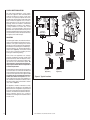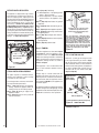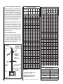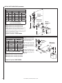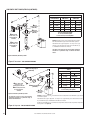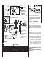
1
INSTALLATION
INSTRUCTIONS
RETAIN THESE INSTRUCTIONS
FOR FUTURE REFERENCE
This appliance may be installed as an OEM installation in a manufactured home (USA only) or
Manufactured Home and must be installed in accordance with the manufacturer's instructions and
the manufactured home construction and safety
standard, Title 24 CPF, Part 3280 or Standard for
Installation in Manufactured Homes, CAN/CSA Z240
MH. This appliance is only for use with the type(s)
of gas indicated on the rating plate. A conversion
kit is supplied with the appliance.
In the Commonwealth of Massachusetts:
DIRECT VENT
SDDV-35/40 SERIES
DIRECT VENT GAS FIREPLACE HEATERS
P/N 700,041M REV. B 11/2006
MODELS
Millivolt Models
SDDV-35NM
SDDV-35PM
SDDV-40NM
SDDV-40PM
Electronic Models
SDDV-35NE
SDDV-40NE
• Installation must be performed by a licensed plumber or
gas fitter;
• See Table of Contents for location of additional Commonwealth of Massachusetts requirements.
A French manual is available upon request. Order P/N 700,041CF
WARNING: IF THE INFORMATION IN THIS MANUAL
IS NOT FOLLOWED EXACTLY, A FIRE OR EXPLOSION MAY RESULT CAUSING PROPERTY DAMAGE,
PERSONAL INJURY OR LOSS OF LIFE.
AVERTISSEMENT: ASSUREZ-VOUS DE BIEN
SUIVRE LES INSTRUCTIONS DONNÉ DANS CETTE
NOTICE POUR RÉDUIRE AU MINIMUM LE RISQUE
D'INCENDIE OU POUR ÉVITER TOUT DOMMAGE
MATÉRIEL, TOUTE BLESSURE OU LA MORT.
FOR YOUR SAFETY: Do not store or use gasoline
or other flammables or liquids in the vicinity of
this or any other appliance.
FOR YOUR SAFETY: What to do if you smell gas:
•
•
•
•
DO NOT light any appliance.
DO NOT touch any electrical switches.
Do not use any phone in your building.
Immediately call your gas supplier from a
neighbor’s phone. Follow your gas suppliers
instructions.
• If your gas supplier cannot be reached, call
the fire department.
Installation and service must be performed by
a qualified installer, service agency or the gas
supplier.
OTL Report No. 116-F-05-5
Ce manuel d’installation est disponible en francais, simplement en
faire la demande. Numéro de la pièce 700,041CF.
POUR VOTRE SÉCURITÉ: Ne pas entreposer ni
utiliser d'essence ni d'autre vapeurs ou liquides
inflammables dans le voisinage de cet appareil ou
de tout autre appareil.
POUR VOTRE SÉCURITÉ: Que faire si vous sentez
une odeur de gaz:
• Ne pas tenter d'allumer d'appareil.
• Ne touchez à aucun interrupteur. Ne pas vous
servir des téléphones se trouvant dans le batiment où vous vous trouvez.
• Evacuez la piéce, le bâtiment ou la zone.
• Appelez immédiatement votre fournisseur de
gaz depuis un voisin. Suivez les instructions du
fournisseur.
• Si vous ne pouvez rejoindre le fournisseur de
gaz, appelez le service dos incendies.
L'installation et service doit être exécuté par un
qualifié installeur, agence de service ou le fournisseur de gaz.
PACKAGING
TABLE OF CONTENTS
Packaging .........................................Page
Introduction ......................................Page
General Information ..........................Page
New York City Approval.....................Page
Requirements for the
Commonwealth of Massachusetts .Page
Safety & Warning Information ..........Page
Cold Climate Insulation .....................Page
Location ............................................Page
Manufactured Home Requirements ..Page
Vent Termination Clearances ............Page
Minimum Clearances to Combustibles..Page
Detailed Installation Steps .................Page
Typical Installation Sequence ...........Page
Step 1. Framing.................................Page
Step 2. Routing Gas Line ..................Page
Fireplace Specifications.....................Page
Step 3. Install the Venting System ....Page
Vertical Termination Systems ............Page
Vent Section Length Tables ...............Page
Vertical Vent Tables and Figures........Page
Horizontal Termination System .........Page
Horizontal Vent Tables and Figures ...Page
Venting Using Flexible Vent Pipe .......Page
Step 4. Field Wiring .........................Page
Step 5. Optional Blower Kit Wiring ..Page
Step 6. Connecting Gas Line ...........Page
Control Compartment Access ...........Page
Step 7. Checking Unit Operation .....Page
Step 8. Installing Logs ...................Page
Step 9. Installing Glass Door ..........Page
Step 10. Burner Adjustments ............Page
Step 11. Hood Installation .................Page
Finishing Requirements ....................Page
Installation Accessories ....................Page
Gas Conversion Kits .................. Page
2
2
2
3
4
5
6
6
7
7
9
10
10
10
10
11
13
14
14
17
19
21
24
25
25
26
27
27
28
30
30
31
31
32
34
This installation manual will help you obtain
a safe, efficient, dependable installation for
your appliance and vent system.
Please read and understand these
instructions before beginning your
installation.
The Millivolt appliances have a millivolt
gas control valve with piezo ignition system
which provides safe, efficient operation. If any
optional accessories that will require electrical
power are to be installed, the electrical power
must be provided at the time of appliance
installation.
The Electronic appliances have an electronic
intermittent pilot ignition system which
provides safe, efficient operation. External
electrical power is required to operate these
appliances.
2
The assembled vented gas fireplace heater is
packaged with:
1 - One log set located in firebox area.
2 - One envelope containing the literature package which consists of the homeowner's
manual, installation instructions, and warranty; envelope is located in the control
compartment.
3 - One vent restrictor to be applied as shown on
Page 13; restrictor is taped to envelope.
4 - One hood located behind the top panel.
5 - One bag of decorative volcanic stone located
in the control compartment.
6 - One bag of glowing embers located in the
control compartment. Introduction
These vented gas fireplace heaters are sealed
combustion, air circulating gas fireplaces designed for residential applications.
Approved Vent Components - These fireplaces
are designed, tested and listed for operation
and installation with, the following vent components only:
• Secure Vent™ Direct Vent System Components,
• Secure Flex™ Flexible Vent Components
manufactured by Security Chimneys International and
• Z-FLEX™ Model GA Venting Systems listed
to UL1777 and ULCS635 manufactured by
Flexmaster Canada Limited.
These approved vent system components are
labeled for identification. DO NOT use any other
manufacturer’s vent components with these
appliances. Use only the correct size venting
(4-1/2" inner & 7-1/2" outer).
These appliances comply with National Safety
Standards and are tested and listed by OMNITest Laboratories, Inc. (Report No. 116-F-05-5)
to ANSI Z21.88b-2003 (in Canada, CSA-2.33b2003), and CAN/CGA-2.17-M91 in both USA and
Canada, as vented gas fireplace heaters.
Both millivolt and electronic versions of
these appliances are listed by OMNI-Test
Laboratories for installation in bedrooms
and Manufactured Homes.
Manufactured Homes See Manufactured Home Requirements on
Page 7 for additional information.
WARNING
Improper installation, adjustment, alteration, service or
maintenance can cause injury
or property damage. Refer to
this manual. For assistance or
additional information consult
a qualified installer, service
agency or the gas supplier.
NOTE: DIAGRAMS & ILLUSTRATIONS ARE NOT TO SCALE.
This appliance is only for use with the type
of gas indicated on the rating plate. This appliance is not convertible for use with other
gases, unless a certified kit is used.
Cet appareil doit être utilisé uniquement
avec les types de gaz indiqués sur la plaque
signalétique. Ne pas l'utiliser avec d'autres
gaz sauf si un kit de conversion certifié est
installé.
Misc. Codes / Standards Installation must conform to local codes. In the
absence of local codes, installation must comply
with the current National Fuel Gas Code, ANSI
Z223.1. (In Canada, the current CAN-1 B149
installation code).
The appliance, when installed, must be electrically grounded & wired in accordance with local
codes or, in the absence of local codes, with the
National Electrical Code, ANSI / NFPA 70-latest
edition, or the Canadian Electrical Code, CSA
C22.1 - latest edition.
GENERAL INFORMATION
Note: Installation and repair should be performed by a qualified service person. The
appliance should be inspected annually by
a qualified professional service technician.
More frequent inspections and cleanings may
be required due to excessive from carpeting,
bedding material, etc.
S'assurer que le brùleur et le compartiment des
commandes sont propres. Voir les instructions
d'installation et d'utilisation qui accompagnent
l'appareil.
Provide adequate clearances around air openings and adequate accessibility clearance for
service and proper operation. Never obstruct
the front openings of the appliance.
These appliances are designed to operate on
natural or propane gas only. To operate on an
alternate gas (i.e. converting a natural gas
model to use propane gas) a field converion
is necessary (see Pages 34 to 36). The use
of any other fuels or combination of fuels will
degrade the performance of this system and
may be dangerous.
These fireplaces are designed as supplemental heaters. Therefore, it is advisable to have
an alternate heat source when installed in a
dwelling.
Millivolt Models - The millivolt appliances are
manually controlled and feature a spark igniter
(piezo) that allows the appliance's pilot gas to
be lit without the use of matches or batteries.
This system provides continued service in the
event of a power outage.
Millivolt models come standard with a manually-modulated gas valve; flame appearance and
heat output can be controlled at the gas valve.
The BTU Input for these appliances is shown
in Tables 1 & 2.
Input Rate (BTU / HR)
27,000 high
21,000 low
SDDV-35NM
30,000 high
23,500 low
SDDV-40NM
Low
High
Natural
Gas
(Lo) 2.2" WC
(.55 kPa)
(Hi) 3.5" WC
(.87 kPa)
Propane
(Lo) 6.3" WC
(1.57 kPa)
(Hi) 10.0" WC
(2.49 kPa)
Table 5
Table 1
Manifold Gas Supply Pressure
(electronic models)
Input (BTU) Manually-Modulated Gas
Valves (millivolt models)
Fuel #
Max. Manifold Pressure
* PROPANE GAS
Natural Gas
(Hi) 3.5" WC (.87 kPa)
Propane
(Hi) 10.0" WC (2.49 kPa)
27,000 high
20,700 low
SDDV-40PM
30,000 high
23,500 low
Table 2
* If field converted - see Pages 34-36
Electronic Models
SDDV-35
27,000
SDDV-40
30,000
Table 3
* if field converted
#36 (.1065") *
18L40 •
#52 (.0635")*
LB-55874D •
* Standard size installed at factory
• Part /Cat. Number
Table 7
Gas Valve Diagrams
See Figure 1 for Millivolt models and Figure 2
For Electronic Models.
SIT Millivolt Gas Valve
HI/LO Variable
Flame Height
Adjustment
Inlet Pressure Tap
Manifold Pressure Tap
These appliances must be isolated from the
gas supply piping system (by closing their
individual manual shut-off valve) during any
pressure testing of the gas supply piping
system at test pressures equal to or less than
1/2 psig (3.5 kPa).
These appliances and their individual shut-off
valves must be disconnected from the gas
supply piping system during any pressure
testing of that system at pressures greater
than 1/2 psig (3.5 kPa).
OF F
LO W
i
t
Input Rate (BTU / HR)
SDDV-40
P IL O T
Natural and *Propane Gas
Model Series
#53 (.0595") *
39L10 •
TH
Electronic Models with Fixed Rate Gas Valve
#40 (.098") *
69L96 •
TP
3.
Test gauge connections are provided on the
front of the millivolt gas control valve, identified IN for the inlet and OUT for the manifold
side. A 1/8" NPT Test gauge connection
is provided at the inlet and outlet side of
the electronic gas control valve.
SDDV-35
TPTH
Electronic models have a fixed rate gas valve.
Input of electronic models is shown in Table
Table 6
drill size (inches)
OT
SDDV-35PM
drill size
(inches)
ON
Input Rate (BTU / HR)
Propane
Gas
OUT
Models
Natural
Gas
Model
Series
PIL
Models
Fuel #
Burner Orifice Sizes
Elevation 0-4500 feet ( 0-1372 meters)
HI
NATURAL GAS
Manifold Gas Supply Pressure
(millivolt models)
IN
Input (BTU) Manually-Modulated Gas
Valves (millivolt models)
Main Gas
Control Knob
Pilot Adjustment
Screw
OFF/PILOT/ON
Figure 1
Honeywell Electronic Gas Valve
Minimum
Maximum
Natural Gas
5.0" WC
(1.24 kPa)
10.5" WC
(2.61 kPa)
11.0" WC
(2.74 kPa)
13.0" WC
(3.23 kPa)
Propane
Inlet
Pressure
Port
IN
OFF
ON
Fuel #
ON / OFF Switch
IGNITER
Inlet Gas Supply Pressure
(all models)
These appliances are tested and approved for
installation at elevations of 0-4500 feet (0-1372
meters) above sea level using the standard burner
orifice sizes (marked with an "*" in Table 7). For
elevations above 4500 feet, contact your gas
supplier or qualified service technician . Install
the appliance according to the regulations of
the local authorities having jurisdiction and, in
the USA, the National Fuel Gas Code NFPA 54
/ ANSI Z223.1 - latest edition or, in Canada, the
CAN1-B149.1 and .2 codes - latest edition.
Manifold Pressure
Port
CONTROL
Tables 4, 5 and 6 show the appliances' gas
pressure requirements:
Orifice Sizes - Sea Level to High Altitude
(All Models)
PSI
Gas Pressure - All Models
Figure 2
Electronic Gas
Control Valve
New York City, New York (MEA)
Table 4
Installation of these fireplaces are approved
for installation in New York City in the US state
of New York.
NOTE: DIAGRAMS & ILLUSTRATIONS ARE NOT TO SCALE.
3
Note: The following requirements reference various Massachusetts
and national codes not contained in this document.
Requirements for the Commonwealth of Massachusetts
For all side wall horizontally vented gas fueled equipment installed in every
dwelling, building or structure used in whole or in part for residential
purposes, including those owned or operated by the Commonwealth and
where the side wall exhaust vent termination is less than seven (7) feet
above finished grade in the area of the venting, including but not limited
to decks and porches, the following requirements shall be satisfied:
Inspection
The state or local gas inspector of the side wall horizontally vented gas
fueled equipment shall not approve the installation unless, upon inspection,
the inspector observes carbon monoxide detectors and signage installed
in accordance with the provisions of 248 CMR 5.08(2)(a)1 through 4.
Exemptions
The following equipment is exempt from 248 CMR 5.08(2)(a)1 through 4:
• The equipment listed in Chapter 10 entitled “Equipment Not Required
To Be Vented” in the most current edition of NFPA 54 as adopted by
the Board; and
Installation Of Carbon Monoxide Detectors
At the time of installation of the side wall horizontal vented gas fueled
equipment, the installing plumber or gasfitter shall observe that a hard
wired carbon monoxide detector with an alarm and battery back-up is
installed on the floor level where the gas equipment is to be installed.
In addition, the installing plumber or gasfitter shall observe that a battery operated or hard wired carbon monoxide detector with an alarm is
installed on each additional level of the dwelling, building or structure
served by the side wall horizontal vented gas fueled equipment. It shall
be the responsibility of the property owner to secure the services of
qualified licensed professionals for the installation of hard wired carbon
monoxide detectors.
In the event that the side wall horizontally vented gas fueled equipment
is installed in a crawl space or an attic, the hard wired carbon monoxide
detector with alarm and battery back-up may be installed on the next
adjacent floor level.
In the event that the requirements of this subdivision can not be met at
the time of completion of installation, the owner shall have a period of
thirty (30) days to comply with the above requirements; provided, however, that during said thirty (30) day period, a battery operated carbon
monoxide detector with an alarm shall be installed.
• Product Approved side wall horizontally vented gas fueled equipment
installed in a room or structure separate from the dwelling, building
or structure used in whole or in part for residential purposes.
MANUFACTURER REQUIREMENTS
Gas Equipment Venting System Provided
When the manufacturer of Product Approved side wall horizontally
vented gas equipment provides a venting system design or venting system components with the equipment, the instructions provided by the
manufacturer for installation of the equipment and the venting system
shall include:
• Detailed instructions for the installation of the venting system design
or the venting system components; and
• A complete parts list for the venting system design or venting system.
Gas Equipment Venting System NOT Provided
When the manufacturer of a Product Approved side wall horizontally
vented gas fueled equipment does not provide the parts for venting the
flue gases, but identifies “special venting systems”, the following requirements shall be satisfied by the manufacturer:
Approved Carbon Monoxide Detectors
Each carbon monoxide detector as required in accordance with the
above provisions shall comply with NFPA 720 and be ANSI/UL 2034
listed and IAS certified.
• The referenced “special venting system” instructions shall be included
with the appliance or equipment installation instructions; and
Signage
• The “special venting systems” shall be Product Approved by the
Board, and the instructions for that system shall include a parts list
and detailed installation instructions.
A metal or plastic identification plate shall be permanently mounted to
the exterior of the building at a minimum height of eight (8) feet above
grade directly in line with the exhaust vent terminal for the horizontally
vented gas fueled heating appliance or equipment. The sign shall read, in
print size no less than one-half (1/2) inch in size, “GAS VENT DIRECTLY
BELOW. KEEP CLEAR OF ALL OBSTRUCTIONS.”
A copy of all installation instructions for all Product Approved side wall
horizontally vented gas fueled equipment, all venting instructions, all
parts lists for venting instructions, and/or all venting design instructions
shall remain with the appliance or equipment at the completion of the
installation.
• Installation and repair must be done by a plumber or gas fitter licensed
in the Commonwealth of Massachusetts.
• The flexible gas line connector used shall not exceed 36 inches (92
centimeters) in length.
• The individual manual shut-off must be a T-handle type valve.
4
NOTE: DIAGRAMS & ILLUSTRATIONS ARE NOT TO SCALE.
SAFETY & WARNIING INFORMATION
WARNING
If the information in this
manual is not follwed
exactly, a fire or explosion
may result causing property damage, personal
injury or loss of life.
WARNING
This appliance is only for use
with the type of gas indicated on
the rating plate. This appliance
is not convertible for use with
other gases, unless a certified
kit is used.
WARNING
These fireplaces are vented heaters. Do not burn wood or other
material in these appliances.
AVERTISSEMENT
Cet appareil doit être utilisé
uniquement avec les types de
gaz indiqués sur la plaque signalétique. Ne pas l'utiliser avec
d'autres gaz sauf si un kit de conversion certifié est installé.
IMPORTANT
It is imperative that the control
compartment, burners and
circulating air passage ways
of the appliance be kept clean.
See Maintenance instructions in
Homeowner's Manual.
WARNING
This appliance may only be fitted
with doors certified for use with
the appliance.
WARNING
Children and adults should be
alerted to the hazards of high
NOTE: DIAGRAMS & ILLUSTRATIONS NOT TO SCALE.
surface temperatures. Use
caution around the appliance
to avoid burns or clothing ignition. Young children should be
carefully supervised when they
are in the same room as the
appliance.
Note: An Optional Screen Door or
Screen Panel for the glass is available (see Homeowners Manual for
ordering information).
AVERTISSEMENT
Surveiller les enfants. Garder les
vêtements, les meubles, l'essence
ou autres liquides à vapeur inflammables lin de l'appareil.
WARNING
Do not place clothing or other
flammable materials on or near
this appliance.
AVERTISSEMENT
Pour utilisation uniquement avec
les portes en verre certifiêes avec
l'appareil.
WARNING
Carbon monoxide poisoning:
early signs of carbon monoxide
poisoning are similar to the flu
with headaches, dizziness and/or
nausea. If you have these signs,
obtain fresh air immediately. Turn
off the gas supply to the appliance
and have it serviced by a qualified professional, as it may not
be operating correctly.
NOTE: DIAGRAMS & ILLUSTRATIONS ARE NOT TO SCALE.
WARNING
Do not use these appliances if
any part has been under water.
Immediately call a qualified,
professional service technician
to inspect the appliances and to
replace any parts of the control
system and any gas controls
which have been under water.
WARNING
Failure to comply with the installation and operating instructions
provided in this document will
result in an improperly installed
and operating appliance, voiding
its warranty. Any change to this
appliance and/or its operating
controls is dangerous. Improper
installation or use of this appliance can cause serious injury or
death from fire, burns, explosion
or carbon monoxide poisoning.
WARNING
Do not attempt to alter or modify
the construction of the appliance or its components. Any
modification or alteration may
void the warranty, certification
and listings of this unit.
AVERTISSEMENT
Ne pas se servir de cet appareil s'il a été plongé dans l'eau,
complètement ou en partie.
Appeler un technicien qualifié
pour inspecter l'appareil et remplacer toute partie du système de
contrôle et toute commande qui
ont été plongés dans l'lau.
IMPORTANT
These appliances must not be
connected to a chimney or flue
serving a separate solid fuel
burning appliance.
5
LOCATION
In selecting the location, the aesthetic and functional use of the appliance are primary concerns.
However, vent system routing to the exterior
and access to the fuel supply are also important.
Consideration should be given to traffic ways,
furniture, draperies, etc., due to elevated surface
temperatures (Figure 3). The location should
also be free of electrical, plumbing or other
heating/air conditioning ducting.
These direct vent appliances are uniquely
suited for installations requiring a utility shelf
positioned directly above the fireplace. Utility
shelves like these are commonly used for locating television sets and decorative plants. Be
aware that this is a heat producing appliance.
Objects placed above the unit are exposed to
elevated temperatures.
To provide for the lowest possible shelf surface
use the alternate rear vent outlet with attached
venting routed in a way to minimize obstructions
to the use of the space above the appliance. Do
not insulate the space between the appliance
and the area above it. See Figure 8. The minimum height from the base of the appliance to
the underside of combustible materials used to
construct a utility shelf in this fashion is shown
in the Table in Figure 8.
RECESSED
INSTALLATION
TOP VENT
TOP VENT
APPLICATION APPLICATION
REAR VENT
TOP VENT
APPLICATION
APPLICATION
APPLICATION
TOP VENT
NT
V E IO N
AR AT
RE LIC
P
AP
For cold climate installations, seal all cracks
around the appliance with noncombustible
material and wherever cold air could enter
the room. It is especially important to insulate
outside chase cavity between studs and under
floor on which the appliance rests, if floor is
above ground level. Gas line holes and other
openings should be caulked or stuffed with
unfaced fiberglass insulation. If the fireplace
is being installed on a cement slab, in cold
climates, a sheet of plywood or other raised
platform can be placed underneath to prevent
conducting cold up into the room. It also helps to
sheetrock inside surfaces and tape for maximum
air tightness and caulk firestops.
AP TOP
PL V
IC EN
AT T
IO
N
COLD CLIMATE INSULATION
TOP VENT
APPLICATION
VERTICAL VENT
(Rear Vent
Application)
HORIZONTAL VENT
(Rear Vent Application
without a chase)
HORIZONTAL VENT
(Rear Vent Application
With a chase)
HORIZONTAL VENT
(Top Vent
Application)
Figure 3 - Typical Locations
The appliance should be mounted on a fully
supported base extending the full width and
depth of the unit. The appliance may be located
on or near conventional construction materials.
However, if installed on combustible materials,
such as carpeting, vinyl tile, etc., a metal or
wood barrier covering the entire bottom surface
must be used.
6
NOTE: DIAGRAMS & ILLUSTRATIONS ARE NOT TO SCALE.
VERTICAL VENT
(Top Vent
Application)
MANUFACTURED HOME
REQUIREMENTS
This appliance may be installed in an aftermarket permanently located, manufactured
home (USA only) or mobile home, where not
prohibited by local codes.
Cet appareil peut être installé dans un maison
préfabriquée (É.-U. seulement) ou mobile déjà
installée à demeure si les réglements locaux
le permettent.
Manufactured Home installations must be
installed in accordance with these instructions
and the following standards / codes:
• Manufactured Home Construction and
Safety Standard Title 24 CFR, Part 3280, or
the current Standard for Fire Safety Criteria
for Manufactured Home Installations, Sites
and Communities ANSI / NFPA 501A in the
USA, and CAN / CSA Z240 MH Mobile Home
Standard in Canada
• (when applicable) The American National
Standard for Manufactured Homes (NCSBCS
/ ANSI A225.1 - latest edition).
VENT TERMINATION CLEARANCES
Horizontal Vent Termination Clearances
These instructions should be used as a guideline and do not supersede local codes in any
way. Install vent according to local codes,
these instructions, the current National Fuel
Gas Code (ANSI-Z223.1) in the USA or the
current standards of CAN/CGA-B149.1 and
-B149.2 in Canada.
The horizontal vent termination must have
a minimum of 3" (76 mm) clearance to any
overhead combustible projection of 2-1/2" (64
mm) or less. See Figure 5. For projections
exceeding 2-1/2" (64 mm), see Figure 6. For
additional vent location restrictions refer to
Figure 6 on Page 8.
Terminate multiple vent terminations according to
the installation codes listed above.
Vertical Vent Termination Clearances
(Gas Vent Rule)
TERMINATION HEIGHTS FOR VENTS ABOVE
FLAT OR SLOPED ROOFS
Horizontal Overhang
2 FT
MIN.
2 FT MIN.
Vent
Termination
Ventilated
Soffit
Unventilated
Soffit
18"
(457 mm)
12"
(305 mm)
3"
(76 mm)
Vertical
Wall
Lowest
Discharge
Opening
Note - See Figure 33 on
Page 20 for the exterior
wall recess allowances
of the square horizontal
termination.
H*
Storm Collar
X
12
Roof Pitch is X/12
CAUTIONS
This appliance must be grounded
to the chassis of the manufactured home in accordance with
local codes or in the absence of
local codes, with the National
Electrical Code ANSI / NFPA 70
- latest edition or the Canadian
Electrical Code CSA C22.1 - latest
edition.
Combustible Projection
2-1/2 inches or less in length
Combustible Projection greater
than 2-1/2 inches in length
Flashing
Ensure that the cross members
are not cut or weakened during
installation. The structural integrity of the manufactured home
floor, wall, and ceiling / roof must
be maintained.
Horizontal Vent Termination Clearances
Terminate single vent caps relative to building
components according to Figure 4.
Termination Kit
Side Elevation View
Figure 5
1 inch (25.4 mm) Minimum
Clearance to Combustibles
Concentric
Vent Pipe
*H = MINIMUM HEIGHT FROM ROOF TO
LOWEST DISCHARGE OPENING OF VENT
The vent / air intake termination clearances
above the high side of an angled roof is as
shown in the following chart:
Termination Heights For Vents
Above Flat Or Sloped Roofs
Ref. NFPA 54 / ANSI Z223.1, 7.6
Roof Pitch
* Feet
* Meters
Flat to 6/12
1.0
0.3
6/12 to 7/12
1.25
0.38
7/12 to 8/12
1.5
0.46
8/12 to 9/12
2.0
0.61
9/12 to 10/12
2.5
0.76
10/12 to 11/12
3.25
0.99
11/12 to 12/12
4.0
1.22
12/12 to 14/12
5.0
1.52
14/12 to 16/12
6.0
1.83
16/12 to 18/12
7.0
2.13
18/12 to 20/12
7.5
2.29
20/12 to 21/12
8.0
2.44
Figure 4
NOTE: DIAGRAMS & ILLUSTRATIONS ARE NOT TO SCALE.
7
EXTERIOR HORIZONTAL VENT TERMINATION CLEARANCE REQUIREMENTS
See Item D in the Text Below.
Center Line
of Termination
Exterior Wall
Inside
Corner Detail
*18”
Horizontal
Termination
G
18”
V
Ventilated Soffit
A
Inside Corner
= 9" in U.S.
A = 12" in Canada
DETAIL D
H
3 ft.
B
C
V
V
L
F
Fixed
Closed
Window
V
C
C
A
Operable
Window
V
C
V
B
D
X
V
3 ft.
J
B
M
B
B
V
I
A
X = Air Supply Inlet
E
A
V = Vent Terminal
= Area where Terminal is NOT permitted
Minimum Clearances
Canadian Installation *
US Installation **
A = Clearance above grade, veranda, porch, deck
or balcony.
12 inches (30 cm) *
12 inches (30 cm) **
B = Clearance to window or door that may be
opened.
6 in. (15.2 cm) for appliances < 10,000 BTU/hr (3kW),
6 in. (15.2 cm) for appliances < 10,000 BTU/hr (3kW),
12 in. (30 cm) for appliances > 10,000 BTU/hr (3kW) and < 9 in. (23 cm) for appliances > 10,000 BTU/hr (3kW) and <
100,000 BTU/hr (30kW), 36 inches (91 cm) for appliances 50,000 BTU/hr (15kW), 12 inches (30 cm) for appliances
> 100,000 BTU/hr (30kW)*
> 50,000 BTU/hr (15kW)*
C = Clearance to permanently closed window
12 inches (305 mm) recommended to prevent window 9 inches (229 mm) recommended to prevent window
condensation
condensation
D = Vertical clearance to ventilated soffit located
above the terminal within a horizontal distance of 18
in. (458 mm) from the center line of the terminal
18 inches (458 mm)
18 inches (458 mm)
E = Clearance to unventilated soffit
12 inches (30 cm)
12 inches (30 cm)
F = Clearance to outside corner
5 inches (12.7 cm)
5 inches (12.7 cm)
G = Clearance to inside corner
6 in. (15 cm)
6 in. (15 cm)
H = Clearance to each inside of center line extended 3 feet (91 cm) within a height of 15 feet above the meter / 3 feet (91 cm) within a height of 15 feet above the meter
above meter / regulator assembly
regulator assembly *
/ regulator assembly **
I = Clearance to service regulator vent outlet
3 feet (91 cm) *
3 feet (91 cm) **
J = Clearance to non-mechanical air supply inlet
to building or the combustion air inlet to any other
appliance
6 in. (15.2 cm) for appliances < 10,000 BTU/hr (3kW), 12 6 in. (15.2 cm) for appliances < 10,000 BTU/hr (3kW), 9
in. (30 cm) for appliances > 10,000 BTU/hr (3kW) and < in. (23 cm) for appliances > 10,000 BTU/hr (3kW) and <
100,000 BTU/hr (30kW), 36 inches (91 cm) for appliances 50,000 BTU/hr (15kW), 12 inches (30 cm) for appliances
> 100,000 BTU/hr (30kW)*
> 50,000 BTU/hr (15kW)*
K = Clearance to mechanical air supply inlet
6 feet (1.8 meters) *
3 feet (91 cm) above, if within 10 feet (3 m) horizontally**
L = Clearance above paved sidewalk or paved
driveway located on public property
7 feet (2.13 m) ‡
7 feet (2.13 m) ‡
M = Clearance under veranda, porch, deck or
balcony
12 in. (30 cm) * ‡
12 in. (30 cm) ** ‡
* In accordance with the current CSA-B149.1 National Gas and B149.2 Propane Installation Code - Latest Editions.
** In accordance with the current ANSI Z223.1 / NFPA 54 National Fuel Codes - Latest Edition.
‡ A vent shall not terminate directly above a sidewalk or paved driveway which is located between two single family dwellings and serves both dwellings.
*‡ Only permitted if veranda, porch, deck or balcony is fully open on a minimum 2 sides beneath the floor.
Figure 6
8
NOTE: DIAGRAMS & ILLUSTRATIONS ARE NOT TO SCALE.
MINIMUM CLEARANCES TO COMBUSTIBLES
Appliance and Vent Clearances
Hearth Extension - A hearth extension is not required with this appliance. If a hearth extension is
used, do not block the lower control compartment door. Any hearth extension used is for appearance
only and does not have to conform to standard hearth extension installation requirements.
The appliance is approved with zero clearance to
combustible materials on all sides (as detailed
in Table 8), with the following exception: When
the unit is installed with one side flush with a
wall, the wall on the other side of the unit must
not extend beyond the front edge of the unit.
In addition, when the unit is recessed, the side
walls surrounding the unit must not extend
beyond the front edge of the unit. See Figure
3 on Page 6.
Wall Finishes / Surrounds / Mantels
Note: Combustible wall finish materials and/or surround materials must not be allowed to encroach
the area defined by the appliance front face (black sheet metal). Never allow combustible materials
to be positioned in front of or overlapping the appliance front face. See Figure 56 on Page 31.
Non-combustible materials, such as surrounds and other appliance trim, may be installed on the
appliance front face with these exceptions: they must not cover any portion of the removable glass
panel or louvers.
Vertical installation clearances to combustible mantels vary according to the depth of the mantel.
See Figure 7. Mantels constructed of non-combustible materials may be installed at any height
above the appliance opening; however, do not allow anything to hang below the hood.
Mantel Depth
MINIMUM CLEARANCES Inches (millimeters)
Back
1/2 (13)
0 (0) Spacers
Sides
1/2 (13)
0 (0) Spacers
Top Spacers
0 (0)
Floor
0 (0)
Bottom of Appliance
To Ceiling
64 (1626)
inches (millimeters)
14 (356)
12 (305)
10 (254)
Vent
3 (76) Top *
1 (25.4) Sides & Bottom
8 (203)
Top of
Appliance
6 (152)
SERVICE CLEARANCES Feet (meters)
Front
4 (102)
3 ft. (0.9 m)
Table 8
12
10
8
6
4
2
(305) (254) (203) (152) (102) (51)
*Note: 3 in. (75 mm) above any horizontal/inclined vent component.
**Note: See Page 10, Step 1 for clearance
requirements to the nailing flange located
at each side of the unit and any screw heads
adjacent to it.
Hood
Figure 7 - Minimum Mantel Clearances
Minimum Distance to Unprotected Side Wall
Combustible Shelf Height - Inches (millimeters)
Model No.
SDDV-35
SDDV-40
Top Vent - with One 90 Degree Elbow
Rear Vent - Straight Out the Back
Secure Vent
Secure Flex
(flex elbow)
Secure Vent
Secure Flex
*53-1/2 (1359)
*55-1/4 (1403)
40-1/4 (1022)
40-1/4 (1022)
* Includes 3” clearance to combustibles (required above vent components)
Do not insulate the
space between the
appliance and the
area above it.
Combustible materials may project beyond the sides of the fireplace opening as long as they are kept within the shaded areas
illustrated here.
At 14" minimum
side wall clearance,
a combustible wall
can project to any
length.
Do not insulate the
space between the
appliance and the
area above it.
At 8-1/4" side
wall clearance, a
combustible wall
can project 12"
45o
Top View of
Fireplace
5 (127)
Combustible Materials
Allowed In Shaded
Area “Safe Zone”
Combustible Walls
shown in dark gray
Shelf Height
(see table)
*Shelf Height
(see table)
12 (305)
17 (432)
Shelf Above Fireplace With Rear Venting
Inches (millimeters)
Shelf Above Fireplace With Top Venting
Figure 8 - Shelf Height Minimum Clearances
14
8-1/4
(356)
(209)
NOTE: DIAGRAMS & ILLUSTRATIONS ARE NOT TO SCALE.
Protected wall shown in white
Figure 9
9
DETAILED INSTALLATION STEPS
The appliance is shipped with all gas controls
and components installed and pre-wired. Remove the shipping carton, exposing the front
glass door. Remove the top and bottom louvered
control panel per instructions on Page 27 (see
Control Compartment Access / Louver Panel
Instructions). Remove the cardboard from
underneath the pressure relief plates, in area
behind top louver panel (see Figure 10). Open
the two latches (located under the firebox floor)
securing the glass door. Remove the door by
tilting it outward at the bottom and lifting it up.
Set the door aside protecting it from inadvertent
damage. See Figure 53 on Page 30.
Pressure Relief Plates
REMOVE
CARDBOARD
BEFORE USING
REMOVE
Step 4. (Page 25) Field Wiring
a. Millivolt Appliances – The operating control
switch is factory installed.
b. Electronic Appliances – Connect 120 VAC
electrical power to the appliance receptacle.
Step 5. (Page 25) Install blower kit (optional
equipment).
Step 6. (Page 26) Make connection to gas supply.
Step 7. (Page 27) Checkout appliance operation.
Step 8. (Page 28) Install the logs, volcanic stone
and glowing embers.
Step 9. (Page 30) Install glass door frame assembly.
Step 10. (Page 30) Adjust burner to ensure proper
flame appearance.
Step 11. (Page 31) Install the hood.
Step 1. FRAMING
CARDBOARD
BEFORE USING
Remove Cardboard Before
Using Appliance
If the appliance is to be elevated above floor
level, a solid continuous platform must be
constructed.
TYPICAL INSTALLATION SEQUENCE
The typical sequence of installation follows,
however, each installation is unique resulting
in variations to those described.
See the Page numbers references in the following steps for detailed procedures.
Step 1. (Page 10) Construct the appliance
framing. Position the appliance within the
framing and secure with nailing brackets.
Step 2. (Page 10) Route gas supply line to
appliance location.
Step 3. (Page 13) Install the vent system and
exterior termination.
Left Side Front Corner of Fireplace Shown
(Right Side Requirements the Same)
Unit Being Secured By Its Nailing Flanges
To The Framing
Note: The nailing flanges, combustible members
and screw heads located in areas directly adjacent
to the nailing flanges, are EXEMPT from the 1/2”
clearance to combustible requirements for the
firebox outer wrapper. Combustible framing may be
in direct contact with the nailing flanges and may
be located closer than 1/2” from screw heads and
the firebox wrapper in areas adjacent to the nailing
flanges. Frame the opening to the exact dimensions
specified in the framing details of this manual.
Figure 11
Frame these appliances as illustrated in Figure
13 on Page 11, unless the appliance is to be
installed in a corner. See Figure 14 on Page
12 for corner framing installations. All framing
details must allow for a minimum clearance to
combustible framing members as shown in
Table 8 on Page 9.
See-Through Model Shown
Figure 10
Unit Nailing Flange
(No clearance to
combustible
framing is required)
Side
Framing
Headers may be in direct contact with the
appliance top spacers but must not be supported by them or notched to fit around them.
All construction above the appliance must be
self supporting. DO NOT use the appliance for
structural support.
The fireplace should be secured to the side framing
members using the unit's nailing flanges - one top
and bottom on each side of the fireplace front. See
Figure 11. Use 8d nails or their equivalent.
STEP 2. ROUTING GAS LINE
Route a 1/2" (13 mm) gas line along the inside
of the right side framing as shown in Figure
12. Gas lines must be routed, constructed and
made of materials that are in strict accordance
with local codes and regulations. All appliances
are factory-equipped with a flexible gas line
connector and 1/2 inch shutoff valve. (See
Step 6 on Page 26).
Right Side Front
Corner of Fireplace Framing
6-1/2"
(152 mm)
3"
(76 mm)
Also see Figure 13.
Left side installation is optional (see Figure 13)
Figure 12 - ROUTE GAS LINE
Continued on Page 12.
10
NOTE: DIAGRAMS & ILLUSTRATIONS ARE NOT TO SCALE.
FIREPLACE SPECIFICATIONS
**Framing With Square Horizontal Termination SV4.5HT-2
Framing Dimensions - Inches (millimeters)
Models
A
B
C
(rear vent)
C
(top vent)
D
**Framing should be constructed
of 2 x 4 or larger lumber.
E
SDDV-35
35-1/4 (895)
40-1/4 (1022) 20-7/8 (530)
23-5/8 (600)
27-1/2 (699)
46-3/4 (1188)
SDDV-40
40-1/4 (1022)
40-1/4 (1022) 20-7/8 (530)
23-5/8 (600)
27-1/2 (699)
46-3/4 (1188)
Notes
Input (BTU) - MV & Electronic
* The Steady State Efficiency numbers based on
maximum vent configuration.
Natural (NG) & Propane (LP) Gas
Models
Due to Lennox' ongoing commitment to quality,
all specifications, ratings and dimensions are
subject to change without notice.
Vent Size
Co-axial DV Vent Size
4-1/2" Inner
7-1/2" Outer
7
(178)
5-1/8
(130)
Input Rate (BTU / HR)
NG
High 27,000
Low 21,000
LP
High 27,000
Low 20,700
NG
High 30,000
Low 23,500
LP
High 30,000
Low 23,500
SDDV-40
VENT FRAMING TOP VENT WITH ONE
90° ELBOW
VENT FRAMING REAR VENT WITH
NO ELBOWS
Fuel
SDDV-35
Unit is shipped with vent seal cap and flue cover
plate installed on both flue outlets.
10-1/2
(267)
12-1/8
(308)
7
5-1/8
(130)
E
B
(178)
12-1/8
(308)
D
C
1/2 A
A
Inches (mm)
C is the required framing depth
dimension when the finish material
(drywall) thickness is 1/2 in. (13mm).
NOTE: DIAGRAMS & ILLUSTRATIONS ARE NOT TO SCALE.
FRAMING
SPACERS
(Top and Sides
and Rear)
G
Product Reference Information
Co-Axial Direct Vent Pipe
Collars (Top & Rear Vent)
Flue Outlet - 4-1/2 (114),
Combustion Air - 7-1/2 (190)
H
Cat.
No.
10-7/8
(275)
Top View
3 (76)
E
Model
Ship.
Wt.(lbs)
Ship.Vol. (Cubic feet)
H4835
SDDV-35NM
128 Lb's
18.3 cu. ft. - 40-1/4 x 36-7/8 x 21-7/8"
H4836
SDDV-35PM
128 Lb's
18.3 cu. ft. - 40-1/4 x 36-7/8 x 21-7/8"
H4837
SDDV-35NE
128 Lb's
18.3 cu. ft. - 40-1/4 x 36-7/8 x 21-7/8"
H4838
SDDV-40NM
142 Lb's
20.9 cu. ft. - 40-1/4 x 41-5/8 x 21-7/8"
H4839
SDDV-40PM
142 Lb's
20.9 cu. ft. - 40-1/4 x 41-5/8 x 21-7/8"
H4840
SDDV-40NE
142 Lb's
20.9 cu. ft. - 40-1/4 x 41-5/8 x 21-7/8"
20-7/8
(531)
Hood
2 (51)
1/2 (13)
C
A
GAS INLET
(Either Side
and bottom)
B
D
10-1/8
(257)
2-1/4
(57)
F
ELECTRICAL
INLET
3 (76)
7
179)
Front View
Right Side View
Fireplace Dimensions - Inches (millimeters)
Figure 13
Model
A
B
C
D
E
F
G
H
SDDV-35
40-1/8 (1019)
37-1/8 (943)
24 (610)
29-1/2 (749)
35-1/8 (892)
27-1/2 (698)
21-1/2 (546)
10-3/4 (273)
SDDV-40
40-1/8 (1019)
37-1/8 (943)
24 (610)
34-1/2 (876)
40-1/8 (1019)
27-1/2 (698)
26-1/2 (675)
13-3/4 (337)
11
FIREPLACE FRAMING SPECIFICATIONS
Notes:
• Venting requirements for rear vent applications in corner installations, the horizontal vent
length “a” to “b,” must not exceed 28 inches (711).
b
*These dimensions occur when one 45 degree elbow is connected directly to the appliance collar.
*F
*In SDDV-35 corner installations, the unit has been moved 1-3/8 in. (35 mm) into the room in
order to achieve a minimum of 5 in. (127 mm) in the F dimension.
7 (178)
*C
Corner Framing With SV4.5HT-2 Termination - Inches (millimeters)
*E
Model
A
B
C
D
E
F
SDDV-35
35-1/8
(892)
65-1/2
(1664)
46-5/16
(1176)
25-11/16
(652)
32-3/4
(832)
5
(127)
SDDV-40
40-1/8
(1019)
67-3/4
(1721)
47-7/8
(1216)
25-11/16
(652)
33-7/8
(860)
5-3/4
(146)
*D
a
A
*B
Back wall of chase/enclosure
(including any finishing materials)
Figure 14
Corner Framing with Square Termination (SV4.5HT-2)
Proper Sizing of Gas Line
Properly size and route the gas supply line
from the supply regulator to the area where
the appliance is to be installed per requirements outlined in the National Fuel Gas Code,
NFPA 54 - latest edition (USA) or B149 - latest
edition (Canada).
Never use galvanized or plastic pipe. Refer to
Table 9 for proper sizing of the gas supply line,
if black iron pipe is being used. Gas lines must
be routed, constructed and made of materials
that are in strict accordance with local codes
and regulations. We recommend that a qualified individual such as a plumber or gas fitter
be hired to correctly size and route the gas
supply line to the appliance. Installing a gas
supply line from the fuel supply to the appliance
involves numerous considerations of materials,
protection, sizing, locations, controls, pressure,
sediment, and more. Certainly no one unfamiliar
and unqualified should attempt sizing or installing gas piping.
12
Inches
(millimeters)
Schedule 40 / Black Iron Pipe
Inside Diameter (Inches)
Schedule 40 Pipe
Length (feet)
Natural
Gas
Propane
Gas
0-10
1/2
3/8
10-40
1/2
1/2
40-100
1/2
1/2
100-150
3/4
1/2
150-200
3/4
1/2
Table 9
Notes:
• All appliances are factory-equipped with a
flexible gas line connector and 1/2 inch shutoff
valve (see Figures 46 & 48).
• See Massachusetts Requirements on Page 4
for additional requirements for installations in
the state of Massachusetts in the USA.
• The gas supply line should Not be connected
to the appliance until Step 6 (Page 26).
NOTE: DIAGRAMS & ILLUSTRATIONS ARE NOT TO SCALE.
• A pipe joint compound rated for gas should be
used on the threaded joints. Ensure propane
resistant compounds are used in propane
applications. Be very careful that the pipe
compound does not get inside the pipe.
• It is recommended to install a sediment trap
in the supply line as close as possible to the
appliance (see Figure 46). Appliances using
Propane should have a sediment trap at the
base of the tank.
• Check with local building official for local code
requirements (i.e. are below grade penetrations
of the gas line allowed?, etc).
IMPORTANT: If propane is used, be aware that
if tank size is too small (i.e. under 100-lbs, if
this is the only gas appliance in the dwelling.
Ref. NPFA 58), there may be loss of pressure,
resulting in insufficient fuel delivery (which
can result in sooting, severe delayed ignition
or other malfunctions). Any damage resulting
from an improper installation, such as this, is
not covered under the limited warranty.
Step 3. INSTALL THE VENT SYSTEM
General Information
These instructions should be used as a guideline and do not supersede local codes in any
way. Install vent according to local codes,
these instructions, the current National Fuel
Gas Code (ANSI-Z223.1) in the USA or the
current standards of CAN/CGA-B149.1 and
-B149.2 in Canada.
Use only approved venting components. See
Approved Vent Components on Page 2.
These fireplaces must be vented directly
to the outside.
Failure to reinstall and securely
tighten cover plate screws could
result in leakage of flue products
into the living space. Vent cover
plate and vent seal plate must
remain securely installed on
unused vent collar. Failure to do
so could result in leakage of flue
products into living space.
TOP VENT SEAL CAP & COVER PLATE
REMOVAL WHEN USING THE TOP VENT
When There Is 3 Feet Or More Of Vertical
Venting, install a vent restrictor (provided) in
the appliance top or rear flue outlet as shown
in Figures 17a & 17b. It is held in place by
friction, only.
TOP VENT
Restrictor Installation
If 3 ft. or more of vertical venting is used, install
a vent restrictor in the top vent of the fireplace
outlet. It can be installed from the inside or
outside of the unit, in the inner fireplace collar.
It is held in place by friction only.
(OUTSIDE UNIT)
SECURING SCREWS
The vent system may not service multiple
appliances, and must never be connected to a
flue serving a solid fuel burning appliance. The
vent pipe is tested to be run inside an enclosing
wall (such as a chase). There is no requirement
for inspection openings in the enclosing wall at
any of the joints in the vent pipe.
Preparing The Appliance Top Or Rear Vent
Outlet
WARNING
VENT SEAL CAP
TOP VENT
CABINET TOP
Restrictor
Inner
Fireplace
Collar
Appliance Top
Vent Outlet
Preparing the Appliance Vent Collar
FIREBOX TOP
Each of the unit's two vent collars are sealed
with a cover plate and a seal cap. The cover
plate and seal cap must be removed from the
cent collar being used. Refer to Figure 15 for
top vent usage and Figure 16 for rear, and
the following steps to prepare the appropriate
collar for use.
From the vent collar being used, remove the
screw securing the vent seal cap. Twist the cap
counterclockwise to disengage it from the vent
collar. Remove and discard the seal cap.
When the top vent is being used, remove the
lintel cover plate by pushing it back towards
the rear of the fireplace by its front flange. It
can then be removed by pulling it forward.
Loosen the two screws in the keyhole slots of
the vent cover plate and remove the remaining
two vent cover plate securing screws. Remove
and discard the vent cover plate. Reinstall and
securely tighten all four cover plate screws.
Reinstall the lintel cover plate.
When the rear vent is being used, from inside
the firebox, remove the two screws securing the
baffle to the rear wall of the firebox, then remove
the baffle. Loosen the two screws in the keyhole
slots of the cover plate and remove the remaining
two cover plate securing screws. Remove and
discard the cover plate. Reinstall and securely
tighten all four cover plate screws. Re-secure
the baffle to the rear wall of the firebox.
Figure 17a
VENT
COVER PLATE
VENT COVER PLATE
SECURING SCREW
LINTEL
LINTEL
COVER PLATE
REAR VENT
Restrictor Installation
PUSH TO BEGIN REMOVAL
PROCESS OF LINTEL COVER PLATE
(INSIDE UNIT)
CROSS SECTION
Figure 15
REAR VENT SEAL CAP & COVER PLATE REMOVAL
WHEN USING THE REAR VENT
If 3 ft. or more of vertical venting is used, install
a vent restrictor in the rear vent of the fireplace
outlet. It can be installed from the inside or
outside of the unit, in the inner fireplace collar.
It is held in place by friction only.
Inner Fireplace
Collar
Appliance Rear
Vent Outlet
SECURING SCREWS
COVER PLATE
SECURING SCREWS
Restrictor
VENT SEAL CAP
BAFFLE
SECURING
SCREWS
Figure 17b
Select Venting System Horizontal or Vertical
BAFFLE
REAR VENT
(INSIDE UNIT)
(OUTSIDE UNIT)
CABINET BACK
Figure 16
CROSS SECTION
NOTE: DIAGRAMS & ILLUSTRATIONS ARE NOT TO SCALE.
With the appliance secured in framing, determine vent routing and identify the exterior
termination location. The following sections
describe vertical (roof) and horizontal (exterior
wall) vent applications. Refer to the section
relating to your installation. A list of approved
venting components is shown on Pages 32
to 34.
13
VERTICAL TERMINATION SYSTEMS (ROOF)
Figure 21 (Page 15), and Figures 26 to
30 (Pages 17 and 18) and their associated
Vertical Vent Tables illustrate the various vertical venting configurations that are possible for
use with these appliances. Secure Vent pipe
applications are shown in these Figures; Secure
Flex pipe may also be used. A Vertical Vent
Table summarizes each system’s minimum and
maximum vertical and horizontal length values
that can be used to design and install the vent
components in a variety of applications.
Both these vertical vent systems terminate
through the roof. The minimum vent height
above the roof and/or adjacent walls is specified in ANSI Z223.1-(latest edition) (In Canada,
the current CAN-1 B149 installation code) by
major building codes. Always consult your local codes for specific requirements. A general
guide to follow is the Gas Vent Rule (refer to
Figure 4 on Page 7).
Vertical (Straight) Installation
Determine the number of straight vent sections
required. 4-1/2" (114 mm), 10-1/2" (267 mm),
22-1/2" (572 mm), 34-1/2" (876 mm) and 461/2" (1181 mm) net section lengths are available
(see Table 11 and Page 32 - Item 3). Plan the
vent lengths so that a joint does not occur at
the intersection of ceiling or roof joists. Refer
to the Vent Section Length Chart.
SV4.5CGV-1
Termination
SV4.5FA OR
SV4.5FB Flashing
AND SV4.5SC
STORM COLLAR
1" (25.4 mm)
Minimum
Clearance to
Combustibles
SV4.5VF
Firestop/Spacer
Vent Section Length Chart
6
12
24
36
48
Net Section
Length (inches)
4½
10 ½
22 ½
34 ½
46
½
Height of Vent
SV4.5L6/12/24/36/48
Vent Sections
When using Secure Flex
use Firestop/Spacer
SF4.5VF
Q
T
Y
Number of Vent Sections
14
Nominal Section
Length (inches)
6
12
24
36
48
Net Section
Length (inches)
4½
10 ½
22 ½
34 ½
46 ½
Height of Vent
*inches
T
O
T
A
L
Q
T
Y
Number of Vent Sections
feet
feet
144
12
1
0
0
0
3
4
4.5
0.375
1
0
0
0
0
1
150
12.5
0
1
0
0
3
4
9
0.75
2
0
0
0
0
2
154.5
12.875
1
1
0
0
3
5
10.5
0.875
0
1
0
0
0
1
15
1.25
1
1
0
0
2
13.375
0
2
0
0
3
5
19.5
1.625
2
1
0
0
0
0
160.5
172.5
14.375
0
0
0
5
0
5
177
14.75
1
0
0
5
0
6
3
21
1.75
0
2
0
0
0
2
22.5
1.875
0
0
1
0
0
1
183
15.25
0
1
0
5
0
6
25.5
2.125
1
2
0
0
0
3
186
15.5
0
0
0
0
4
4
31.5
2.625
0
3
0
0
0
3
190.5
15.875
1
0
0
0
4
5
34.5
2.875
0
0
0
1
0
1
196.5
16.375
0
1
0
0
4
5
37.5
3.125
1
1
1
0
0
3
205.5
17.125
0
1
1
5
0
7
43.5
3.625
0
2
1
0
0
3
207
17.25
0
0
0
6
0
6
45
3.75
0
0
2
0
0
2
211.5
17.625
1
0
0
6
0
7
46.5
3.875
0
0
0
0
1
1
217.5
18.125
0
1
0
6
0
7
49.5
4.125
1
0
2
0
0
3
229.5
19.125
0
0
1
6
0
7
2
232.5
19.375
0
0
0
0
5
5
237
19.75
1
0
0
0
5
6
241.5
20.125
0
0
0
7
0
7
246
20.5
1
0
0
7
0
8
252
21
0
1
0
7
0
8
264
22
0
0
1
7
0
8
276
23
0
0
0
8
0
8
279
23.25
0
0
0
0
6
6
280.5
23.375
1
0
0
8
0
9
283.5
23.625
1
0
0
0
6
7
289.5
24.125
0
1
0
0
6
7
301.5
25.125
0
0
1
0
6
7
310.5
25.875
0
0
0
9
0
9
315
26.5
1
0
0
9
0
10
51
55.5
4.25
4.625
1
0
0
1
0
2
0
0
1
0
3
57
4.75
0
0
1
1
0
2
66
5.25
0
2
2
0
0
4
67.5
5.625
0
0
3
0
0
3
69
5.75
0
0
0
2
0
2
72
6
1
0
3
0
0
4
73.5
6.125
1
0
0
2
0
3
79.5
6.625
0
1
0
2
0
3
81
6.75
0
0
0
1
1
2
90
7.5
0
2
1
0
1
4
91.5
7.625
0
0
2
0
1
3
93
7.75
0
0
0
0
2
2
96
8
1
0
1
2
0
4
325.5
27.125
0
0
0
0
7
7
97.5
8.125
1
0
0
0
2
3
330
27.5
1
0
0
0
7
8
102
103.5
108
8.5
8.625
9
2
0
1
0
0
0
0
0
0
0
3
3
2
0
0
4
3
4
336
28
0
1
0
0
7
8
345
28.75
0
0
0
10
0
10
349.5
29.125
1
0
0
10
0
11
114
9.5
0
2
0
0
2
4
372
31
0
0
0
0
8
8
117
9.75
1
0
5
0
0
6
376.5
31.375
1
0
0
0
8
9
118.5
9.875
1
1
0
3
0
5
379.5
31.625
0
0
0
11
0
11
126
10.5
0
0
1
3
0
4
418.5
34.875
0
0
0
0
9
9
1
0
1
3
0
5
423
35.25
1
0
0
0
9
10
465
38.75
0
0
0
0
10
10
135
11.25
0
0
6
0
0
6
138
11.5
0
0
0
4
0
4
139.5 11.625
0
0
0
0
3
3
142.5 11.875
1
0
0
4
0
5
Table 10a
* Convert inches into metric equivalent measure, as follows:
Figure 18
T
O
T
A
L
*inches
130.5 10.875
40' Max
(12.2 M)
Vent Section Length Chart
Nominal
Section Length
(inches)
Millimeters (mm) = Inches x 25.4
Centimeters (cm) = Inches x 2.54
Meters (M) = Inches x .0254
NOTE: DIAGRAMS & ILLUSTRATIONS ARE NOT TO SCALE.
Table 10b
Effective Vent Length
Model
Effective Length
SV4.5L6
4-1/2"
SV4.5L12
10-1/2"
SV4.5L24
22-1/2"
SV4.5L36
34-1/2"
SV4.5L48
46-1/2"
Table 11
Vertical (Offset) Installation
Analyze the vent routing and determine the
quantities of vent sections and number of elbows
required. Refer to Vertical Vent Figures and
Tables on Pages 17 & 18 to select the type of
vertical installation desired. Vent sections are
available in net lengths of 4-1/2" (114 mm),
10-1/2" (267 mm), 22-1/2" (572 mm), 34-1/2
" (876 mm) and 46-1/2" (1181 mm). Refer to
the Vent Section Length Chart on Page 14 for
an aid in selecting length combinations. Elbows
are available in 90° and 45° configurations. Refer
to Figure 22 on Page 16 for the SV4.5E45 and
SV4.5E90 elbow dimensional specifications.
Where required, a telescopic vent section
(SV4.5LA) may be used to provide the installer
with an option in installing in tight and confined
spaces or where the vent run made up of fixed
length pieces develops a joint in a undesirable
location, or will not build up to the required
length. The SV4.5LA Telescopic Vent Section
has an effective length of from 1-1/2" (38 mm)
to 7-1/2 " (191 mm). The SV4.5LA is fitted with
a locking inclined channel end (identical to a
normal vent section component) and a plain end
with 3 pilot holes. Slip the plain end over the
locking channel end of a standard SV4.5 vent
component the required distance and secure
with three screws.
Maintain a minimum 1" (25 mm) clearance to
combustible materials for all vertical elements.
Clearances for all horizontal elements are 3"
(76 mm) on top, 1" (25 mm) on sides and 1"
(25 mm) on the bottom.
A. Frame ceiling opening - Use a plumb line
from the ceiling above the appliance to locate
center of the vertical run. Cut and/or frame an
opening, 10-1/2" x 10-1/2" (267mm x 267mm)
inside dimensions, about this center mark
(Figure 19).
10-1/2" Min.
(267 mm)
10-1/2" Min.
(267 mm)
B. Attach vent components to appliance
- Secure Vent SV4.5 direct vent system components are unitized concentric pipe components
featuring positive twist lock connections (see
Figure 20).
To add another vent component to a length of
vent run, align the dimpled end over the inclined
channel end of the previously installed section,
adjusting the radial alignment until the four locking dimples are aligned with the inlets of the four
incline channels of the previous section.
All of the appliances covered in this document
are fitted with collars having locking inclined
channels. The dimpled end of the vent components fit over the appliance collar to create
the positive twist lock connection.
Push the vent component against the previous
section until it fully engages, then twist the
component clockwise running the dimples down
and along the incline channels until they seat at
the end of the channels. This seating position
is indicated by the alignment of the arrow and
dimple as shown in Figure 20.
Arrow
Align the dimple (four places) of the
upper vent section with the opening
of the locking incline channel on the
lower vent section or appliance collar. Twist vent component clockwise
to engage and seal until arrow and
dimple align.
Dimple
Locking Incline
Channel
Connected Vent
Sections
Appliance Collar or
Vent Section
Arrow
Figure 20
To attach a vent component to the appliance collar,
align the dimpled end over the collar, adjusting the
radial alignment until the four locking dimples are
aligned with the inlet of the four inclined channels
on the collar (refer to Figure 20). Push the
vent component against the collar until it fully
engages, then twist the component clockwise,
running the dimples down and along the incline
channels until they seat at the end of the channels. The unitized design of the Secure Vent
components will engage and seal both the inner
and outer pipe without the need for sealant or
screws. If desired, a #6 x 1/2" screw may be
used at the joint, but is not required as the pipe
will securely lock when twisted.
D. Install firestop/spacer at ceiling - When
using Secure Vent, use SV4.5VF firestop/spacer
at ceiling joists; when using Secure Flex, use
SF4.5VF firestop/spacer. If there is living space
above the ceiling level, the firestop/spacer
must be installed on the bottom side of the
ceiling. If attic space is above the ceiling, the
firestop/spacer must be installed on the top side
of the joist. Route the vent sections through the
framed opening and secure the firestop/spacer
with 8d nails or other appropriate fasteners at
each corner. Remember to maintain 1" (25
mm) clearance to combustibles, framing
members, and attic or ceiling insulation
when running vertical chimney sections.
Attic insulation shield (96K94) may be used
to obtain the required clearances indicated
here. See installation accessories, Pages
32 through 34.
E. Support the vertical vent run sections Note - Proper venting support is very important.
The weight of the vent must not be supported
by the firplace in any degree.
Support the vertical portion of the venting
system every 8 feet (2.4m) above the fireplace
vent outlet.
Blocking
Note: An elbow may also be attached to the
appliance collar. Attach in the same manner
as you would a vent section.
Support Straps
(Plumber's tape)
C. Attach vent components to each other
- Other vent sections may be added to the
previously installed section in accordance with
the requirements of the vertical vent Figures
and Tables.
8 feet (2.4 m)
Maximum
1 inch (25.4
mm) minimum
clearance to
combustibles
Figure 19
Figure 21
NOTE: DIAGRAMS & ILLUSTRATIONS ARE NOT TO SCALE.
15
One method of support is by utilizing field provided support straps (conventional plumber's
tape). Secure the plumber's tape to the framing
members with nails or screws. Loop the tape
around the vent, securing the ends of the tape
to the framing. If desired, sheet metal screws #6
x 1/2" length may be used to secure the support
straps to the vent pipe. Refer to Figure 21.
F. Change vent direction to horizontal/inclined
run - At transition from or to a horizontal/inclined run, install the SV4.5E45 and SV4.5E90
elbows in the same manner as the straight vent
sections. The elbows feature a twist section to
allow them to be routed about the center axis
of their initial collar section to align with the
required direction of the next vent run element.
Twist elbow sections in a clockwise direction
only so as to avoid the possiblity of unlocking
any of the previously connected vent sections.
See Figure 22.
C
D
Framing Dimensions for Roof
Inches (millimeters)
Pitch
C
D
0/12
10-1/2 in.
(267 mm)
10-1/2 in.
(267 mm)
6/12
10-1/2 in.
(267 mm)
12 in.
(305 mm)
12/12
10-1/2 in.
(267 mm)
17-3/4 in.
(451 mm)
K. Install the vertical termination - The final
step involves installation of the SV4.5CGV-1
Vertical Termination. Extend the vent sections
to the height as shown in the "Vertical vent termination section" on Page 7. The SV4.5CGV-1
Vertical Termination (Figure 25) can be installed
in the exact same fashion as any other Secure
Vent section. Align the termination over the
end of the previously installed section, adjusting the radial alignment until the four locking
dimples of the termination are aligned with
the inlets of the four incline channels of the
last vent section. Push the termination down
until it fully engages, then twist the termination
clockwise running the dimples down and along
the incline channels until they are seated at the
end of the channels.
Figure 23 - Roof Framing
8-1/8"
7-5/8”
(194
(206 mm)
mm)
4-13/16
(122 mm)
Swivel Joint
(360° swivel)
SV4.5E45
45° Elbow)
Swivel Joint
(360° swivel)
SV4.5E90
90° Elbow)
Figure 22
G. Continue installation of horizontal/inclined
sections - Continue with the installation of the
straight vent sections in horizontal/inclined run
as described in Step C. Install support straps
every 5 ft. (1.52 m) along horizontal/inclined
vent runs using conventional plumber’s tape.
See Page 19, Figure 31. It is very important
that the horizontal/inclined run be maintained
in a straight (no dips) and recommended to be
in a slightly elevated plane, in a direction away
from the fireplace of 1/4 " rise per foot (20 mm
per meter) which is ideal, though rise per foot
run ratios that are smaller are acceptable all the
way down to at or near level. Use a carpenter’s
level to measure from a constant surface and
adjust the support straps as necessary.
I. Install the roof flashing - Extend the vent
sections through the roof structure. Install the
roof flashing over the vent section and position such that the vent column rises vertically
(use carpenters level) (Figure 24 ). Nail along
perimeter to secure flashing or adjust roofing
to overlap the flashing edges at top and sides
only and trim where necessary. Seal the top
and both sides of the flashing with waterproof
caulking.
J. Install the storm collar - Install the storm
collar, supplied with the flashing, over the
vent/flashing joint. See Figure 24. Loosen the
storm collar screw. Slide collar down until it
meets the top of the flashing. Tighten the adjusting screw. Apply non-combustible caulking
or mastic around the circumference of the joint
to provide a water tight seal.
Storm
Collar
It is important to maintain the required clearances to combustibles: 1" (25 mm) at all sides
for all vertical runs; and 3" (76 mm) at the top,
1" (25 mm) at sides, and 1" (25 mm) at the
bottom for all horizontal/inclined runs.
H. Frame roof opening - Identify location for
vent at the roof. Cut and/or frame opening per
Roof Framing Chart and Figure 23.
16
Figure 24
NOTE: DIAGRAMS & ILLUSTRATIONS ARE NOT TO SCALE.
Figure 25
If the vent system extends more than 5 feet (1.5
m) above the roof flashing, stabilizers may be
necessary. Additional screws may be used at
section joints for added stability. Guide wires
may be attached to the joint for additional support on multiple joint configurations.
VERTICAL VENT FIGURES/TABLES
Note: Secure Vent (rigid vent pipe) is shown
in the Figures; Secure Flex (flexible vent pipe)
may also be used.
WARNING
Under No Circumstances, May Separate Sections of Concentric Flexible
Vent Pipe Be Joined Together.
Notes:
• It is very important that the horizontal/inclined run be maintained in a straight (no
dips) and recommended to be in a slightly
elevated plane, in a direction away from the
fireplace of 1/4" rise per foot (20 mm per
meter) which is ideal, though rise per foot
run ratios that are smaller are acceptable all
the way down to at or near level.
• SV4.5VF (Secure Vent), SF4.5VF (Secure
Flex) firestop/spacer must be used anytime
vent pipe passes through a combustible
floor or ceiling. SV4.5HF (Secure Vent),
SF4.5HF (Secure Flex)firestop/spacer must
be used anytime vent pipe passes through
a combustible wall.
• Two 45 degree elbows may be used in place
of one 90 degree elbow. The same rise to
run ratios, as shown in the venting Figures
for 90 elbows, must be followed if 45 degree
elbows are used.
• AN ELBOW IS ACCEPTABLE AS 1 FOOT OF
VERTICAL RISE EXCEPT WHERE AN ELBOW
IS THE ONLY VERTICAL COMPONENT IN
THE SYSTEM (See Figure 35).
Table A
H Maximum
When using Secure Flex, use Firestop /
V Minimum
feet
(meter)
feet
(meter)
2
(0.610)
1
(0.305)
4
(1.219)
2
(0.610)
6
(1.829)
3
(0.914)
8
(2.438)
4
(1.219)
Spacer SF4.5VF.
V + H = 40 feet (12.2 meters) Max.
H = 8 feet (2.4 meters) Max.
Ratio V to H ratio is 1:2
Ceiling Firestop /
Spacer (SV4.5VF)
Example: If 8 feet of (H) horizontal vent run
is needed, then 4 feet minimum (V) vertical
vent will be required.
This table shows a 1(V) to 2(H) ratio. For
every 1 foot of (V) vertical, you are allowed 2
feet of (H) horizontal run, up to a maximum
horizontal run of 8 feet.
V
H
Figure 27 - Rear Vent - ONE 90 DEGREE ELBOW
Table B
H
H Maximum
Ceiling Firestop /
Spacer (SV4.5VF)
Ceiling Firestop /
Spacer (SV4.5VF)
40 feet
(12.2 meters)
Maximum
V1
V Minimum
feet
(meter)
feet
(meter)
5
(1.524)
5
(1.524)
1
(0.305)
10
(3.048)
2
(0.610)
15
(4.572)
3
(0.914)
20
(6.096)
4
(1.219)
Elbow Only
V + V1 + H = 40 feet (12.2 m) Max.
H = 20 feet (6.096 meters) Max.
V
Example: If 20 feet of (H) horizontal vent run
is needed, then 4 feet minimum of (V) vertical
vent will be required.
Wall Firestop/
Spacer (SV4.5HF)
When using Secure Flex, use Firestop / Spacer
SF4.5VF
A Vent Restrictor, as shown in Figure 18
Page 13, must be used in this application
When using Secure Flex, use Firestop /
Spacer SF4.5VF.
When using Secure Flex, use Firestop /
Spacer SF4.5HF.
This table shows a 1(V) to 5(H) ratio. For
every 1 foot of (V) vertical, you are allowed 5
feet of (H) horizontal run, up to a maximum
horizontal run of 20 feet.
An elbow is acceptable as 1 foot of vertical
rise except where an elbow is the only vertical
component in the system. See Figure 35.
Figure 28 - Top Vent - TWO 90 DEGREE ELBOWS
Figure 26 - Top Vent - STRAIGHT
NOTE: DIAGRAMS & ILLUSTRATIONS ARE NOT TO SCALE.
17
VERTICAL VENT FIGURES/TABLES (CONTINUED)
Table C
H+H1 Maximum
H Maximum
H1
V Minimum
feet
(meter)
feet
(meter)
feet
(meter)
5
(1.524)
2
(0.610)
1
(0.305)
10
(3.048)
4
(1.219)
2
(0.610)
15
(4.572)
6
(1.829)
3
(0.914)
20
(6.096)
8
(2.438)
4
(1.219)
V + V1 + H + H1 = 40 feet (12.2 m) Max
H = 8 feet (2.438 meters) Max.
H + H1 = 20 feet (6.096 meters) Max.
Ceiling
Firestop / Spacer
(SV4.5VF)
Wall Firestop/
Spacer (SV4.5HF)
Ceiling
V1
Firestop / Spacer
(SV4.5VF)
When using Secure Flex, use Firestop / Spacer SF4.5VF
When using Secure Flex, use Firestop / Spacer SF4.5HF
Example: If 20 feet total (H+H1) horizontal vent run is needed,
then 4 feet minimum of (V) vertical vent will be required.
V
This table shows a 1(V) to 5(H) ratio. For every 1 foot of (V)
vertical, you are allowed 5 feet of (H+H1) horizontal run up to a
maximum total horizontal run of 20 feet.
Figure 29 - Rear Vent - THREE ELBOWS
Table D
V Minimum
H + H1 Maximum
feet
(meter)
feet
(meter)
5
(1.524)
5
(1.524)
1
(0.305)
10
(3.048)
2
(0.610)
15
(4.572)
3
(0.914)
20
(6.096)
4
(1.219)
Elbow Only
H + H1 = 20 feet (6.096 m) Max.
V + V1 + H + H1 = 40 ft. (12.192 m) Max.
H
Example: If 20 feet total (H+H1)
horizontal vent run is needed,
then 4 feet minimum of (V) vertical vent will be required.
This table shows a 1(V) to 5(H)
ratio. For every 1 foot of (V)
vertical run, you are allowed 5
feet of (H) horizontal run up to a
maximum (H+H1) horizontal run
of 20 feet.
Ceiling
An elbow is acceptable as 1 foot
of vertical rise except where
an elbow is the only vertical
component in the system. See
Figure 35.
When using Secure Flex, use Firestop / Spacer SF4.5VF
When using Secure Flex, use Firestop / Spacer SF4.5HF
Figure 30 - Top Vent - THREE ELBOWS
18
Firestop / Spacer
(SV4.5VF)
V1
NOTE: DIAGRAMS & ILLUSTRATIONS ARE NOT TO SCALE.
Wall Firestop/
Spacer (SV4.5HF)
H
V
H1
Support Brackets
Building
Support
Framing
TYPICAL HORIZONTAL VENT INSTALLATION
Horizontal / Inclined Run
SV4.5HT-2
Termination
Shown
SV4.5E90
Elbow
Ceiling
Vertical
Rise
SV4.5L6/12/24/36/48
Vent Sections
Firestop / Spacer
SV4.5VF
Support Bracket Spacing
Every 5 ft (1.52 m)
When Using Secure Flex,
Use Firestop / Spacer SF4.5VF
See Figure 18 on Page 14 or Figure 21 on
Page 15 for vertical vent section support.
Figure 31
HORIZONTAL (OUTSIDE WALL)
TERMINATION SYSTEM
Figure 31, and Figures 34 to 40 on Pages
21 to 23 and their associated Horizontal Vent
Table illustrate the various horizontal venting
configurations that are possible for use with
these appliances. Secure Vent pipe applications
are shown in these Figures; Secure Flex pipe
may also be used. A Horizontal Vent Table summarizes each system’s minimum and maximum
vertical and horizontal length values that can be
used to design and install the vent components
in a variety of applications.
Both of these horizontal vent systems terminate
through an outside wall. Building Codes limit or
prohibit terminating in specific areas. Refer to
Figure 6 on Page 8 for location guidelines.
Secure Vent SV4.5 direct vent system components are unitized concentric pipe components
featuring positive twist lock connection, (refer
to Figure 20 on Page 15). All of the appliances covered in this document are fitted with
collars having locking inclined channels. The
dimpled end of the vent components fit over
the appliance collar to create the positive twist
lock connection.
A. Plan the vent run Analyze the vent routing and determine the
types and quantities of sections required
4-1/2" (114 mm), 10-1/2" (267 mm), 22-1/2" (572
mm), 34-1/2" (876 mm) and 46-1/2" (1181 mm)
net section lengths are available. Plan the vent
lengths so that a joint does not occur at the intersection of ceiling or roof joists. Make allowances
for elbows as indicated in Figure 22.
Maintain a minimum 1" (25 mm) clearance to
combustibles on the vertical sections. Clearances for the horizontal runs are; 3" (76 mm)
on top, 1" (25 mm) on sides, and 1" (25 mm)
at the bottom.
Exterior
Wall
Fireplace
B. Frame exterior wall opening Locate the center of the vent outlet on
the exterior wall according to the dimensions shown in Figure 13 on Page 10. Cut
and/or frame an opening, 10-1/2" x 12-1/8"
(267 mm x 308mm) inside dimensions, about
this center.
C. Frame ceiling opening - If the vertical route
is to penetrate a ceiling, use plumb line to locate
the center above the appliance. Cut and/or frame
an opening, 10-1/2" x 10-1/2" (267 mm x 267
mm) inside dimensions, about this center (refer
to Figure 19 on Page 15).
D. Attach vent components to appliance - To
attach a vent component to the appliance collar,
align the dimpled end over the collar, adjusting the radial alignment until the four locking
dimples are aligned with the inlets of the four
incline channels on the collar (refer to Figure
20 on Page 15).
Push the vent component against the collar
until it fully engages, then twist the component
clockwise, running the dimples down and along
the incline channels until they seat at the end
of the channels.
The unitized design of the Secure Vent
components will engage and seal both the
inner and outer pipe elements with the same
procedure. Sealant and securing screws are
not required.
Note: An elbow may also be attached to the
appliance collar. Attach in the same manner
as you would a vent section.
E. Attach vent components to each other - Other
vent sections may be added to the previously installed section in accordance with the requirements
of the vent tables. To add another vent component
to a length of vent run, align the dimpled end of
the component over the inclined channel end of
the previously installed section,
SV4.5HT-2
Termination
Shown
NOTE: DIAGRAMS & ILLUSTRATIONS ARE NOT TO SCALE.
adjusting the radial alignment until the four locking dimples are aligned with the inlets of the four
incline channels of the previous section. Push
the vent component against the previous section
until it fully engages, then twist the component
clockwise running the dimples down and along
the incline channels until they seat at the end of
the channels.This seating position is indicated
by the alignment of the arrow and dimple as
shown in Figure 20 on Page 15.
F. Install firestop/spacer at ceiling When using Secure Vent, use SV4.5VF firestop/
spacer at ceiling joists; when using Secure Flex,
use SF4.5VF firestop/spacer. If there is living
space above the ceiling level, the firestop/ spacer
must be installed on the bottom side of the
ceiling. If attic space is above the ceiling, the
firestop/ spacer must be installed on the top side
of the joist. Route the vent sections through the
framed opening and secure the firestop/spacer
with 8d nails or other appropriate fasteners at
each corner.
Remember to maintain 1" (25 mm) clearance
to combustibles, framing members, and attic
or ceiling insulation when running vertical
chimney sections.
G. Support the vertical run sections See Section E on Page 15.
H. Change vent direction - At transition from or
to a horizontal/inclined run, install the SV4.5E45
and SV4.5E90 elbows in the same manner as
the straight vent sections. The elbows feature a
twist section to allow them to be routed about the
center axis of their initial collar section to align
with the required direction of the next vent run
element. Twist elbow sections in a clockwise
direction only so as to avoid the possiblity of
unlocking any of the previously connected vent
sections. See Figure 22 on Page 16.
19
I. Continue installation of horizontal/inclined
sections - Continue with the installation of the
straight vent sections in horizontal/inclined run
as described in Step E. Install support straps
every 5 ft. (1.52 m) along horizontal/inclined
vent runs using conventional plumber’s tape.
See Figure 31. It is very important that the
horizontal/inclined run be maintained in a
straight (no dips) and recommended to be in
a slightly elevated plane, in a direction away
from the fireplace of 1/4" rise per foot (20 mm
per meter) which is ideal, though rise per foot
run ratios that are smaller are acceptable all the
way down to at or near level.
To help minimize water infiltration it is
recommended that the Firestop/Spacer
(SV4.5HF) be installed on the exterior
side of the wall.
SV4.5 HT-2
Termination
7"
(178)
12¹⁄₈"
(308 mm)
10¹⁄₂"
(267mm)
5¹⁄₈"
(130 mm)
3"
(76 mm)
1"
(25.4 mm)
Adapter
SV4.5RCH
It is important to maintain the required clearances to combustibles: 1" (25 mm) at all sides
for all vertical runs; and 3" (76 mm) at the top,
1" (25 mm) at sides, and 1" (25 mm) at the
bottom for all horizontal/inclined runs.
J. Assemble vent run to exterior wall - If not
previously measured, locate the center of the
vent at the exterior wall. Prepare an opening as
described in Step B. Assemble the vent system
to point where the terminus of the last section is
located relative to the exterior surface to which
the termination is to be attached (see Figures
32 & 33 and Table 12 on Page 21.
If the terminus of the last section is not within
this distance, use the telescopic vent section
SV4.5LA, as the last vent section. For wall
thicknesses greater than that shown in Figure
33 and Table 12 on Page 21. This table lists
the additional venting components needed (in
addition to the termination and adapter) for a
particular range of wall thicknesses.
K. Attach termination adapter - Attach the
adapter (adapter - SV4.5RCH - provided with the
termination) to the vent section or telescoping
vent section, elbow or appliance collar as shown
in Figures 32 & 33 in the same manner as any
SV4.5 vent component (refer to Step E).
L. Install Firestop/Spacer at exterior wall
- When using the square termination, install
SV4.5HF (Secure Vent), SF4.5HF (Secure Flex)
Firestop/Spacer over the opening at the exterior
side of the framing, long side up, with the 3 inch
spacer clearance at the top as shown in Figure
32, and nail into place.
(The Firestop/Spacer may also be installed over
the opening at the interior side of framing).
IMPORTANT
The vent termination is hot while
in operation and for a period of
time following the use of the fireplace. To prevent contact with hot
surfaces, we recommend the use
of a Termination Guard. See Items
12 and 13 on Page 32. This can be
purchased at your local dealer.
20
Note: Centerline of Vent Piping is
NOT the Same as the Centerline of
the Framed Opening.
See Figure 13 on Page 11 for Min.
Distance to Base of Appliance.
6 to 48 inch Vent Section,
Telescopic vent section,
Elbow or Appliance Collar
Base of Appliance
Figure 32 - INSTALLING SQUARE HORIZONTAL TERMINATION (SV4.5HT-2)
Use silicone caulking to seal
the top and sides of the
termination, up to the
underlayment, stucco, or
masonry wall surface.
Caulk
Siding
Maximum Wall Thickness
10 in. (254 mm) Interior Surface of
Finished Wall
Maximum Extent of
Vent Run Sections
Relative to Exterior
Surface of Framing
Last Vent Section.
Use Telescopic Vent
Section (SV4.5LA), If
Necessary
Exterior Surface of Siding
Exterior Surface of
Framing
6 in. to 9-1/4 in.
(152 to 235 mm)
SV4.5 HT-2
Termination
Caulk
SV4.5 HT-2
Termination
Stucco
Adapter
SV4.5RCH
For thicknesses greater
1-1/4” Maximum Recess of
Square Termination
into Exterior Finishing Material
than 10", see Table 12
Figure 33
Venting Connection and Exterior Wall Recessing of the Horizontal Square
Termination (SV4.5HT-2).
Horizontal terminations have been designed to perform in a wide range of weather conditions. Our terminations meet or exceed industry standards.
When selecting the locations of your horizontal terminations, do not place the termination where water from eaves and adjoining rooflines may create a heavy flow of cascading water onto the termination cap. If the cap must be placed where the possibility of
cascading water exists, it is the responsibility of the builder to direct the water away
from the termination cap by using gutters or other means.
Take care to carefully follow the installation instructions for the termination, including
the use of silicone caulking where required.
NOTE: DIAGRAMS & ILLUSTRATIONS ARE NOT TO SCALE.
M. Install the Square Termination (SV4.5HT-2)
Install the square termination - For the last step , from outside the
exterior wall, slide the collars of the termination onto the adapter (the
outer inside the outer and the inner outside the inner) until the termination seats against the exterior wall surface to which it will be attached.
Orient the housing of the termination with the arrow pointed upwards.
Secure the termination to the exterior wall. The horizontal termination
must not be recessed into the exterior wall or siding by more than the
1-1/4" (32 mm) as shown in Figure 33.
See Table 12 as an aid in venting component selection for a particular
range of exterior wall thicknesses.
WARNING
Under no circumstances, may separate sections of
concentric flexible vent pipe be joined together.
Table F
HORIZONTAL VENT FIGURES/TABLES
Notes:
• Secure Vent components (rigid vent pipe and terminal) are shown in
the Figures; Secure Flex components (flexible vent pipe and terminal)
may also be used.
• Two 45 degree elbows may be used in place of one 90 degree elbow.
The same rise to run ratios, as shown in the venting Figures for 90
elbows,must be followed if 45 degree elbows are used.
• SV4.5VF (Secure Vent), SF4.5VF (Secure Flex) firestop/spacer must be
used anytime vent pipe passes through a combustible floor or ceiling.
SV4.5HF (Secure Vent), SF4.5HF (Secure Flex) firestop/spacer must
be used anytime vent pipe passes through a combustible wall.
• It is very important that the horizontal/inclined run be maintained
in a straight (no dips) and recommended to be in a slightly elevated
plane, in a direction away from the fireplace of 1/4" rise per foot (20
mm per meter) which is ideal, though rise per foot run ratios that are
smaller are acceptable all the way down to at or near level.
• The tables show a 1(V) to 5(H) ratio up to a maximum horizontal run
of 20 feet except for installations where an elbow is the only vertical
vent section in the system (see Figure 35).
• AN ELBOW IS ACCEPTABLE AS 1 FOOT OF VERTICAL RISE EXCEPT
WHERE AN ELBOW IS THE ONLY VERTICAL COMPONENT IN THE
SYSTEM. See Figure 35.
H Maximum
feet
(meter)
3
(.914)
Vent Components Required
Termination Kit Only
6 to 9-1/4 (152 to 235)
Termination Kit and
(SV4.5L6)
6 In. Vent Section
10-1/2 to 13-3/4 (267 to 349)
Termination Kit and 12 in. Vent Section
(SV4.5L12)
16-1/2 to 19-3/4 (419 to 502)
Termination Kit & Telescopic Section (SV4.5LA
2 to 7-1/2") & 6" vent section (SV4.5L6)
11 to 19-3/4 (279 to 502)
(meter)
Elbow Only
H
V
When using Secure Flex,
use Firestop/Spacer
SF4.5HF
Wall
Firestop/Spacer
(SV4.5HF)
See Table 12 as an aid in venting component selection for a particular
range of exterior wall thicknesses.
Figure 35 - Top Vent ONE 90 DEGREE ELBOW - ELBOW CONNECTION AT APPLIANCE
Example: If 20 feet of (H) horizontal vent run is needed, then
4 feet minimum of (V) vertical
vent will be required.
Table G
V Minimum
H Maximum
feet
(meter)
feet
(meter)
5
(1.524)
1
(0.305)
10
(3.048)
2
(0.610)
15
(4.572)
3
(0.914)
(6.096)
4
(1.219)
20
Note: See Figure 33 showing wall thickness range
when using SV4.5HT-2 termination kit only.
Table 12
feet
Square termination
(SV4.5HT-2) shown.
Venting Components Required for Various Exterior Wall Thicknesses, when using Square Termination Kit (SV4.5HT-2)
Exterior Wall Thickness
- inches (mm)
V Minimum
This table shows a 1(V) to
5(H) ratio. For every 1 foot
of vertical, you are allowed 5
feet of (H) horizontal run up to
a maximum (H) horizontal run
of 20 feet.
V + H = 40 feet (12.2 m) Max.
H = 20 ft. (6.096 m) Max.
H
When using Secure Flex,
use Firestop/Spacer
SF4.5VF.
H = 28 in. (711 mm) Maximum.
When using Secure Flex,
use Firestop/Spacer
SF4.5HF
V
When using Secure Flex,
use Firestop/Spacer
SF4.5HF.
H
Wall Firestop/Spacer
Wall Firestop/Spacer
(SV4.5HF)
(SV4.5HF)
Square termination
(SV4.5HT-2) shown.
7 in. (178 mm)
Square termination
(SV4.5HT-2) shown.
Figure 34 - Rear Vent - NO ELBOWS
Ceiling
Firestop/Spacer
(SV4.5VF)
See Table 12 as an aid in venting component selection
for a particular range of exterior wall thicknesses.
Figure 36 - Top Vent - ONE 90 DEGREE ELBOW ELBOW CONNECTION NOT DIRECTLY AT APPLIANCE
NOTE: DIAGRAMS & ILLUSTRATIONS ARE NOT TO SCALE.
21
HORIZONTAL VENT FIGURES/TABLES (CONTINUED)
Table H
H
H1
When using
Secure Flex, use
Firestop/Spacer
SF4.5VF.
V
H+H1 Maximum
V Minimum
H Maximum
feet
(meter)
feet
(meter)
feet
(meter)
5
(1.524)
2
(0.610)
1
(0.305)
Wall
Firestop/Spacer
(SV4.5HF)
10
(3.048)
4
(1.219)
2
(0.610)
15
(4.572)
6
(1.829)
3
(0.914)
Ceiling
Firestop/Spacer
(SV4.5VF)
20
(6.096)
8
(2.438)
4
(1.219)
V + H + H1 = 40 feet (12.2 m) Max
H = 8 feet (2.438 meters) Max.
H + H1 = 20 feet (6.096 meters) Max.
Example: If 20 feet of (H + H1) horizontal vent run is needed,
then 4 feet minimum of (V) vertical vent will be required.
When using
Secure Flex, use
Firestop/Spacer
SF4.5HF.
This table shows a 1(V) to 5(H) ratio. For every 1 foot of (V)
vertical, you are allowed 5 feet of (H+ H1) horizontal run, up
to a maximum horizontal run of 20 feet.
See Table 12 on Page 21 as an aid in venting component
selection for a particular range of exterior wall thicknesses.
Square termination (SV4.5HT-2) shown.
Figure 37 - Rear Vent - TWO 90 DEGREE ELBOWS
Wall Firestop/Spacer
Table J
(SV4.5HF)
H + H1 Maximum
H
H1
Note - When using
Secure Flex, use
Firestop/Spacer SF4.5VF.
V
Wall Firestop/Spacer
When using Secure Flex,
(SV4.5HF)
use Firestop/Spacer
SF4.5HF.
Ceiling
Firestop/Spacer
(SV4.5VF)
V Minimum
feet
(meter)
feet
(meter)
3
(0.914)
5
(1.524)
1
(0.305)
10
(3.048)
2
(0.610)
15
(4.572)
3
(0.914)
20
(6.096)
4
(1.219)
Elbow Only
V + H + H1 = 40 feet (12.2 m) Max.
H + H1 = 20 ft. (6.096 m) Max.
Square termination (SV4.5HT-2) shown.
Example: If 20 feet of (H + H1) horizontal vent run is needed, then 4 feet minimum of (V) vertical
vent will be required.
See Table 12 on Page 21 as an aid in venting
component selection for a particular range of
exterior wall thicknesses.
This table shows a 1(V) to 5(H) ratio. For every 1 foot of (V) vertical, you are allowed 5 feet of (H+
H1) horizontal run, up to a maximum horizontal run of 20 feet.
An elbow is acceptable as 1 foot of vertical rise except where an elbow is the only vertical component
in the system. See Figure 35.
Figure 38 - Top Vent - TWO 90 DEGREE ELBOWS
22
NOTE: DIAGRAMS & ILLUSTRATIONS ARE NOT TO SCALE.
HORIZONTAL VENT FIGURES / TABLES (CONTINUED)
Table K
Wall Firestop/Spacer
H + H1 + H2 Maximum
(SV4.5HF)
H1
H2
feet
(meter)
feet
(meter)
feet
(meter)
5
(1.524)
2
(0.610)
1
(0.305)
10
(3.048)
4
(1.219)
2
(0.610)
15
(4.572)
6
(1.829)
3
(0.914)
20
(6.096)
8
(2.438)
4
(1.219)
Square termination
(SV4.5HT-2) shown.
use Firestop/Spacer
SF4.5VF.
When using Secure
Flex, use Firestop/Spacer
SF4.5HF.
V + H + H1 + H2 = 40 feet (12.2 m) Max
H = 8 feet (2.438 meters) Max.
H + H1+ H2 = 20 feet (6.096 meters) Max.
Ceiling
Firestop/Spacer
(SV4.5VF)
When using Secure Flex,
V Minimum
H Maximum
Example: If 20 feet total (H+H1+H2) horizontal vent
run is needed, then 4 feet minimum of (V) vertical
vent will be required.
V
This table shows a 1(V) to 5(H) ratio. For every
1 foot of (V) vertical, you are allowed 5 feet of
horizontal run up to a maximum total (H+H1+H2)
horizontal run of 20 feet.
See Table 12 on Page 21 as an aid in venting
component selection for a particular range of
exterior wall thicknesses.
H
Figure 39 - Rear Vent - THREE 90 DEGREE ELBOWS
When using Secure Flex,
Table L
use Firestop/Spacer
SF4.5VF.
When using Secure
Flex, use Firestop/Spacer
SF4.5HF.
H1
Ceiling
Firestop/Spacer
(SV4.5VF)
H
Wall Firestop/Spacer
(SV4.5HF)
feet
(meter)
5
(1.524)
feet
(meter)
5
(1.524)
1
(0.305)
10
(3.048)
2
(0.610)
15
(4.572)
3
(0.914)
20
(6.096)
4
(1.219)
Elbow Only
H + H1 = 20 feet (6.096 m) Max.
V + V1+ H + H1 = 40 ft. (12.192 m) Max.
V1
V
Square termination
(SV4.5HT-2) shown.
See Table 12 on Page
21 as an aid in venting
component selection for
a particular range of exterior wall thicknesses.
V Minimum
H + H1 Maximum
Example: If 20 feet total (H+H1) horizontal
vent run is needed, then 4 feet minimum of
(V) vertical vent will be required.
Wall Firestop/Spacer
(SV4.5HF)
This table shows a 1(V) to 5(H) ratio. For every
1 foot of (V) vertical, you are allowed 5 feet
of (H+ H1) horizontal run, up to a maximum
horizontal run of 20 feet.
An elbow is acceptable as 1 foot of vertical
rise except where an elbow is the only vertical
component in the system. See Figure 35.
Figure 40 - Top Vent - THREE 90 DEGREE ELBOWS
NOTE: DIAGRAMS & ILLUSTRATIONS ARE NOT TO SCALE.
23
VERTICAL OR HORIZONTAL VENTING USING
SECURE FLEX KITS AND COMPONENTS
Secure Flex venting kits and components
may be used in any venting application in
place of rigid Secure Vent (SV4.5) direct vent
components. All restrictions, clearances and
allowances that pertain to the rigid piping apply
to the flexible venting. Secure Flex kits may
not be modified; also, under no circumstances
may separate sections of flex pipe be joined
together.
Using adapter (SV4.5RF), Secure Flex kits
may be added to the end of a vent run made
up of rigid Secure Vent (SV4.5) vent sections
provided that doing so does not violate any of
the venting length, height, routing, horizontal
to vertical ratio requirements or clearance
considerations detailed in this manual.
Secure Flex kits come with an adapter that
can be fitted to the inclined channel end of the
last Secure Vent (SV4.5) vent section in a rigid
system in the exact same fashion as any other
Secure Vent section.
Align the dimpled end of the adapter over
the previously installed section or appliance
collar, adjusting the radial alignment until the
four locking dimples of the adapter are aligned
with the inlets of the four incline channels of
the last vent section or collar. Push on the
adapter until it fully engages, then twist the
adapter clockwise running the dimples down
and along the incline channels until they seat
at the end of the channels.
Attach the flexible vent to the adapter as follows (see Figure 41):
A. Install the Inner Flex Pipe 1. Install the small gear clamp loosely around
the inner flexible vent pipe, push it back out
of the way.
2. Apply a bead of Mill-Pac Black (700° F) high
temperature sealant - Catalog No. 10K81
to the inner adapter collar, approximately
1/2 inch from the end.
3. Pull and extend the inner flexible vent
pipe.
4. Slide the inner flex pipe over the adapter collar. Ensure the flexible vent pipe completely
engages the adapter collar to a distance of
1-3/4 inches from the end, and that it is free
from damage or tears.
5. Slide the gear clamp down and tighten it
fully to secure the flexible vent to the adapter
inner collar approximately 3/4 inch from the
end of the flex.
6. Install three screws 120 degrees apart
through the flexible vent pipe and into the
adapter collar just below the gear clamp to
provide additional security to the connection.
24
Flex Vent
Note: Outer Pipe Is Pulled Away To Show
The Detail of The Inner Pipe
Securing Screw - 3 Places
Equidistant (equally spaced)
Just Below Gear Clamp)
APPLY ONLY MIL-PAC BLACK
HIGH TEMPERATURE SEALANT
(Cat. No. 10K81) to the outside
surface of both collars of the
adapter (be especially careful to
fill the grooves of the outer collar
to be covered by the flexible pipe)
and slide flexible pipe over inner
and outer adapter collars.
Gear Clamps
1-3/4 inch (44 mm) Flexible
Pipe and Adapter Outer Collar
Overlap
1-3/4 in. (44 mm) Flexible
Pipe and Adapter Inner Collar
Overlap
Adapter (SV4.5RF)
Figure 41
Attach Adapter to Appliance
Collar, or Secure Vent Sections
B. Install the Outer Flex Pipe 1. Install the large gear clamp loosely around
the outer flexible vent pipe, push it back out
of the way.
2. Apply a bead of Mill-Pac Black (700° F) high
temperature sealant - Catalog No. 10K81)
to the outer adapter collar; to the grooves
of the collar which extend approximately 1
inch from the end and to the flat surface,
approximately 1-3/8 inches from the end.
3. Pull and extend outer flexible vent pipe.
4. Slide the outer flex pipe over the adapter collar. Ensure the flexible vent pipe completely
engages the adapter collar to a distance of
1³⁄₄ inches from the end, and that it is free
from damage or tears.
5. Slide the gear clamp down and tighten it
fully to secure the flexible vent to the adapter
outer collar approximately 3/4 inch from the
end of the flex.
6. Install three screws 120 degrees apart
through the flexible vent pipe and into the
adapter collar just below the gear clamp to
provide additional security to the connection.
C. Route Flex Vent Ensure that the flex vent is properly routed to
provide the required clearance. Do not allow the
flexible vent to bend in a radius tighter than 5"
(127 mm). Refer to Figure 42. Space out the
internal flex vent spacers evenly - approximately
every 6 inches - and avoid kinking of inner pipe.
Support horizontal sections of flex with metal
straps at 2 foot (0.61 m) intervals.
D. Install Firestop / Spacers at ceilings and
walls - When Secure Flex penetrates a wall or
ceiling, a firestop / spacer is required: use the
SF4.5 VF firestop / spacer for ceilings and the
SF4.5 HF firestop / spacer for walls.
NOTE: DIAGRAMS & ILLUSTRATIONS ARE NOT TO SCALE.
Securing Screw
- 3 Places, 120° apart
(equally spaced) Just
Below Gear Clamp
See the appropriate sections and Figures shown
throughout the venting section for their installation requirements.
Flexible Vent
Section
5” (127 mm)
Radius
Minimum
Figure 42
E. Attach Flex Vent to Termination Secure Flex components can be purchased
separately and attached to bulk lengths of Secure Flex flexible tubing cut to size at the job
site. Secure the flexible vent to the Secure Flex
terminations in the same manner (see Figure
41) as it was attached to the adapter.
Note: Secure Flex vent must be attached to
Secure Flex terminations only. DO NOT substitute Secure Vent terminations or the Secure
Vent adapter for Secure Flex components.
The collars of Secure Flex terminations and
adapters have a different diameter than that
used with the Secure Vent pipe. Additionally,
Secure Flex components have an extended
length center tube for use in attaching the
flexible vent.
Step 4. FIELD WIRING
Refer to Section A for millivolt appliances and
Section B for electronic appliances. The gas
valve is set in place and pre-wired at the factory
on both models.
CAUTION
Ensure that wires are positioned
away from hot surfaces and sharp
edges.
CAUTION
Label all wires prior to disconnection
when servicing controls. Wiring
errors can cause improper and dangerous appliance operation.
CAUTION
Do not connect the optional wall
switch for burner operation to a
120 Volt AC power supply.
A. SIT Millivolt Wiring
(See Figure 43) –
1. Select any of the following optional controls:
appliance-mounted (rocker switch) or wallmounted switch, wall thermostat, or the
standard or deluxe remote control kits. If appliance-mounted ON/OFF control is selected
mount it in the gas valve mounting bracket.
2. If wall-mounted ON/OFF control or thermostat is selected mount it in a convenient
location on a wall near the fireplace.
3. Wire the control within the millivolt control
circuit using the 15 feet of 2 conductor wire
supplied with the unit . Caution: do not
connect the optional wall switch to a 120V
power supply.
4. Alternatively, the appliance may be operated
without the use of the controls indicated in
Step 1, solely by manipulating the gas valve
control knob. In order to use this method,
twist the free ends of the two conductor wire
(which would otherwise go to the standard
ON/OFF switch or Optional Switch) together
as shown in Figure 43.
Note: Wire is located inside the control
compartment
Note: The supplied 15 feet of 2 conductor wire
has one end of each conductor connected to
the gas valve circuit and the other end of each
conductor placed loose inside the control
compartment.
3. Connect the power supply wires (including
the ground supply wire) as shown in Figures
44 & 45. (If the field-provided J-box/outlet
box is being used, all of the outlet box wiring
must be field-provided).
4. Locate and install a low voltage (24V) wallmounted switch or thermostat (both fieldprovided)in the desired location.
5. Connect the low voltage wire, located inside
the control compartment, to the wall-mounted
switch or thermostat.
Note: The supplied 15 feet of 2 conductor wire
has one end of each conductor connected to
the gas valve circuit and the other end of each
conductor placed loose inside the control
compartment.
6. Insert the control circuit plug into the unswitched receptacle of the outlet box.
7. After wiring is complete, mount the outlet box
to the J-Box.
B. Electronic Wiring (See Figure 45) –
Note: The electronic appliance must be connected to the main power supply.
Note: The gas valve-mounted ON/OFF switch is
shown in Figure 48. It is integral with the gas
valve and should be set to the ON position.
The junction box is located on the right side of
the appliance. It contains a factory installed and
wired outlet box (duplex receptacle). Also, an
optional field-provided junction box with receptacle may be installed at the front of the control
compartment on either side of the cabinet. See
Figure 44. It will be held in place by a conduit
fitting and locknut (field-provided).
Step 5. WIRING - OPTIONAL FORCED AIR
BLOWER KIT
1. Route a 3-wire 120Vac 60Hz 1ph power supply
to the appliance junction box.
2. If the factory-provided outlet/junction box at
the right rear of the fireplace is being used,
remove the outlet box from the junction box
by removing two screws.
FBK-100, FBK-200 and FBK250 Kits
(See Figures 44 & 45) An electrical outlet box (receptacle) is factory
-provided for the installation of the FBK-100,
FBK-200 and FBK-250 forced air blower kits.
(An optional field-provided outletbox/J-Box
may also be used. Electrical power must be
connected to either of these receptacles in order
to operate these blowers. Install the blower
kits according to the installation instructions
provided with the kits.
Optional J-Box/Outlet Box
(Left Side Shown)
* Optional
Control Switch
TH
Thermopile
TH
TP
* Twist wires together to operate unit solely
by manipulating the gas valve control
knob; or connect wires to optional control
switch (wall switch, remote control or
wall thermostat to operate unit.
TP
TP
*
Schematic
Representation
Only
Field Wired
* Optional Kits Installed - ON/OFF wall switch,
unit mounted burner ON/OFF switch, wall
thermostat or remote control receiver.
See Figure 13 on Page
11 for Optional Electrical
Inlet Knockout Location
Factory
Wired
*Field-Provided
Junction Box
and Duplex
Receptacle
*Narrow (2-1/8" Wide)
J-Box Required
Figure 44
• Note: If any of the original wire as supplied must be replaced,
it must be replaced with Type AWM 105 C - 18 gage wire.
Figure 43- SIT Millivolt Wiring Diagram
NOTE: DIAGRAMS & ILLUSTRATIONS ARE NOT TO SCALE.
25
Plug blower
into this
receptacle
Green
White
Ground - Green
Neutral - White
120 VAC - Black
Black
Gas Flex Line Connector
Gas
Valve
3/8" NPT x 1/2" x 3/8" Flare
Flare Fitting Shut-off Valve
Junction Box
Blower
Ground
* Wall-mounted
ON/ OFF Blower
Switch or Variable
Speed Control Switch.
Tab
Broken
Tab Intact
Red
Green
Ground
Screw
BK
W
G
J-BOX WIRING FOR
WALL SWITCH
BLOWER CONTROL
Hot
Side of
Receptacle
3"
Min
3/8" Flex Tubing
1/2" x 3/8"
Reducer
Gas
Stub
3/8" Nipple
3/8" Union
3/8" Close Nipple
3/8" Shut-off Valve
*A Sediment Trap is recommended to prevent moisture
and debris in gas line from damaging the valve.
Note:The gas supply line must be installed in accordance with building codes by a qualified installer
approved and/or licensed as requed by the locality.
In the Commonwealth of Massachusetts, installation must be performed by a licensed plumber or
gas fitter.
Relay Module C/W FBK-250 only. Plug blower
into J-Box receptacle for FBK-100 or FBK-200
application. See View A for J-Box wiring.
120 VAC
View A
J-Box Wiring when
using unit mounted
relay module.
Neutral
Side of
Receptacle
*Sediment
Trap
Figure 46 - GAS CONNECTION
Optional Blower
Junction Box
*OFF/ON Switch
(Integral with
Gas Valve)
Pilot Burner
Assembly
Step 6. CONNECTING GAS LINE
Honeywell
Electronic
Gas
Valve
Igniter
Connector
BL
BL
Transformer
BK
R
BK
Optional Control Switch
BK
W
GROUND
BL
24 V
Secondary
120 VAC
Primary
BK = BLACK BL = BLUE
R = RED
W = WHITE
G = GREEN
Field Wired
Factory
Wired
* Leave the OFF/ON switch, which is
integral with the gas valve, in the ON
position.
**Optional Control Switches: Wall
Switch, Wall Thermostat or Remote
Control Receiver.
Notes:
1. If any of the original wire as supplied
must be replaced, use Type AWM 105°C
- 18 gage wire ONLY.
2. 120 VAC, 60 Hz - Less than 3 Amps.
Caution: label all wires prior to
disconnection when servicing controls.
Wiring errors can cause improper and
dangerous operation.
Schematic Representation Only
Electronic Wiring Diagram (Honeywell) Showing Blower Wiring for Optional FBK-100, FBK-200 & FBK-250 Kits
Figure 45
CAUTION
Ground supply lead must be connected to the wire attached to the green
ground screw located on the outlet box. See Figure 47. Failure to do so
will result in a potential safety hazard. The appliance must be electrically
grounded in accordance with local codes or, in the absence of local codes,
the National Electrical Code, ANSI/NFPA 70-latest edition. (In Canada, the
current CSA C22-1 Canadian Electrical Code).
26
NOTE: DIAGRAMS & ILLUSTRATIONS ARE NOT TO SCALE.
Make gas line connections. All codes require a
shut-off valve mounted in the supply line. Figure
46 illustrates two methods for connecting the
gas supply. The flex-line method is acceptable
in the U.S., however, Canadian requirements
vary depending on locality. Installation must
be in compliance with local codes.
These appliances are equipped with a gas flex
line for use (where permitted) in connecting
the appliance to the gas line. A gas flex line
is provided to aid in attaching the direct vent
appliance to the gas supply. The gas flex line
can only be used where local codes permit. See
Figure 46 for flex line description. The flex line
is rated for both natural gas and propane gas.
A manual shut off valve is also provided with
the flex line.
The incoming gas line should be piped into
the valve compartment and connected (see
Figures 47 & 48). The millivolt control
valve has a 3/8" (10 mm) NPT thread
inlet port. The electronic control valve
has a 1/2" (13 mm) NPT thread inlet port
and is fitted with a 1/2" x 3/8" (13 mm x
10 mm) NPT fitting.
Secure all joints tightly using appropriate
tools and sealing compounds (ensure propane
resistant compounds are used in propane
applications).
Optional: Seal around the gas line to prevent
cold air leakage.
TEST ALL CONNECTIONS FOR GAS LEAKS
(FACTORY AND FIELD):
WARNING
Never use an open flame to
check for leaks.
Turn on gas supply and test for gas leaks using a
gas leak test solution (also referred to as bubble
leak solution). Note: Using a soapy water solution
(50% dish soap, 50% water) is an effective leak
test solution but it is not recommended, because
the soap residue that is left on the pipes/fittings
can result in corrosion over time.
A. Light the appliance (refer to the lighting
instructions label in control compartment or
homeowner's manual).
B. Brush all joints and connections with the gas
leak test solution to check for leaks. If bubbles
are formed, or gas odor is detected, turn the
gas control knob (off/pilot/on) to the “OFF”
position. Either tighten or refasten the leaking
connection, then retest as described above.
C. When the gas lines are tested and leak free be
sure to rinse off the leak testing solution,
CONTROL COMPARTMENT ACCESS /
LOUVER PANEL INSTRUCTIONS
(Ref. Figures 47 & 48)
NOTE: The top louvered panel and the bottom
louvered control panel door remove and install
the same way as follows:
On millivolt systems, the piezo igniter, HI/LO
flame adjustment knob, and pilot and main
gas OFF/ON control knob are located below
the glass panel enclosure. The gas valve for
electronic systems is also located below the
glass enclosure panel. See Figure 48.
The top 3/8" (10 mm) at the pilot generator
(thermopile) and the top 1/8" min (tip) of the
quick drop out thermocouple should be engulfed
in the pilot flame. The flame should project 1"
(25 mm) beyond the hood at all three ports
(See Figure 49).
Reinstalling Control Compartment Door:
To reinstall, insert the hook catches on each
side of the door into the corresponding slots
in the control compartment opening, then
gently push forward and slide down until it
locks in place.
To light the burner; rotate the gas valve control
knob counterclockwise to the “ON” position
then turn “ON” the OFF/ON switch (installed
at Step 4).
Step 7. CHECKING APPLIANCE OPERATION
With the gas line installed, run initial system
checkout before closing up the front of the
appliance. Follow the pilot lighting instructions
provided in the Homeowner's Care and Operation Instructions. For piezo igniter location see
Figure 48 (millivolt appliances only).
Note: The (pull-out) Lighting instructions label
can be found in the control compartment
(see Figure 48).
When first lighting the appliance, it will take
a few minutes for the line to purge itself of
air. Once purging is complete, the pilot and
burner will light and operate as indicated in
the instruction manual. Subsequent lightings
of the appliance will not require such purging.
Inspect the pilot flame.
The gas controls can be found behind the control
compartment access door.
SIT Millivolt Appliance Checkout
Removing Control Compartment Door:
Open the door by gently lifting it upward until the
hook catches on boths sides clear the locating
slots. Then pull door out to remove.
The pilot flame should be steady, not lifting
or floating. Flame should be blue in color with
traces of orange at the outer edge.
D. Turn on burner then observe the individual
tongues of flame on the burner. Make sure
all ports are open and producing flame evenly
across the burner. If any ports are blocked, or
partially blocked, clean out the ports.
OPENING CONTROL
COMPARTMENT DOOR
Observe the individual tongues of flame on
the burner. Make sure all ports are open and
producing flame evenly across the burner. If
any ports are blocked, or partially blocked,
clean out the ports.
Replace logs if removed for pilot inspection.
Sit Millivolt Pilot Assembly
Proper Pilot Flame Appearance
Igniter Rod
Hood
Thermocouple
3/8" Min.
(9 mm)
Pilot
Nozzels
Figure 49
Thermopile
To light the burner; turn “ON” the remote wall
switch and rotate the gas valve control knob
counterclockwise to the “ON” position.
Control Compartment
Glass Door is Above
Control Compartment
Lift the Lower Control
Compartment Door
up and pull out to
remove.
OFF/PILOT/ON (gas control knob)
HI/LO (flame height
control knob)
Gas Flex Line
Latch for
Glass Door
Optional OFF/ON
Switch Can be
Installed Here
Hook Catch
Gas Valve
Piezo Igniter
Control Valve
Out
'Pull-out' lighting instructions label
is located in control compartment
Up
Lower Control
Compartment Door
Figure 48
Figure 47
NOTE: DIAGRAMS & ILLUSTRATIONS ARE NOT TO SCALE.
27
Electronic Appliance Checkout
To light the burner, turn ‘ON’ the optional remote
wall switch and turn the gas control switch to
the “ON” position. Ensure the Igniter lights the
pilot. The pilot flame should engulf the flame
rod as shown in Figure 50.
Electronic Pilot Assembly
Proper Pilot Flame Appearance
Proper Flame
Adjustment
Pilot
Nozzels
Flame Rod
Hot Surface
Igniter
Figure 50
Step 8. INSTALL VOLCANIC STONE,
GLOWING EMBERS AND LOGS
1. Remove the front glass enclosure panel
(see Removing Glass Enclosure Panels on
Page 30).
2. Carefully remove the log set box from
the firebox. Next, remove embers and
volcanic stone from the control compartment. Handle logs carefully to prevent
breakage.
3. Install Decorative Volcanic stone - Mound
up a portion of the volcanic stone in front
of the burner in a pleasing pattern.
4. Placement of Glowing Embers Separate the Embers (rockwool) into pieces
about the size of a quarter (see Figure 51).
Keep the pieces fluffed up, not matted.
Distribute these pieces over the surface of
the burner, as shown in Figure 52. Do not
use more than is necessary. Ensure that the
main burner slots remain uncovered by the
ember material.
Note: This appliance is provided with enough
Glowing Embers for several applications, do
not use all that is in a new bag at one time. For
best glowing effect, replace the ember material
annually.
5. Placement of Logs The logs have locating notches which correspond to locating brackets and holes which
correspond to locating pins to help ensure
that they are properly positioned. Proper log
placement is critical to prevent sooting.
28
DO NOT attempt to install the
logs until the appliance installation has been completed, the
gas line connected and tested
for leaks and the initial burner
operation has been checked
out.
3/8" to 1/2"
(9 -13 mm)
Ground
Electrode
WARNING
WARNING
WARNING
The size and position of the log
set is critical to achieve a safe,
reliable and attractive flame
pattern. Any attempt to use a
different log set in the fireplace
will void the warranty and will
result in incomplete combustion, sooting, and poor flame
quality.
This appliance is not designed
to burn wood. Any attempt to
do so could cause irrep arable
damage to appliance and prove
hazardous to your safety.
WARNING
If logs are not installed according
to the log installation instructions, flame impingement and
improper combustion could
occur and result in soot and/or
excessive production of carbon
monoxide (CO), a colorless,
odorless, toxic gas.
Glowing Embers
Separate into Quarter
Size (separate) Pieces
REFERENCE
Firebox Accessories / Parts
Cat. No.
Model No.
88L53
FGE
80L42
FDVS
Description
Bag of Glowing Embers
(1 oz. rockwool)
Bag of Decorative
Volcanic stone
Table 13
NOTE: DIAGRAMS & ILLUSTRATIONS ARE NOT TO SCALE.
Bag of Glowing
Embers (rockwool)
Figure 51
Log Installation Instructions (refer to Figure 52)
Carefully position the ceramic fiber logs into the firebox as shown
here. Logs should be placed in the order shown and per the following
instructions.
1. (See photo #1) Place embers on the front and sides of the burner.
Do NOT place embers over any of the slots on the burner. Place the
volcanic stone in front of the burner per instructions in Figures 52
(also see Placement of Glowing Embers & Install Decorative Volcanic
Stone on Page 28).
2. (See photo #2) Place the rear log (A) as shown. Position the 2
notches on the bottom of the log over the 2 corresponding locating
brackets.
3. (See photo #3) Place the right front log (B) as shown. The right
locating pin on burner fits into corresponding hole on the bottom of
log. Position the notch on the bottom of the log over the right front
locating bracket (the bracket is shown in photo #1).
4. (See photo #4) Place the left front log (C) as shown. The left locating pin on burner fits into corresponding hole on the bottom of log.
Position the notch on the bottom of the log over the left front locating
bracket (the bracket is shown in photo #1).
MODEL SDDV-35 & SDDV-40
Log Placement Instructions
A
SDDV-35 Log Set Shown.
The 35 & 40 log sets are
the same except for
width of rear log.
LOG SET
SSDV-35 Cat. # H5044, SSDV-40 Cat. # H5045
* Item
Description
A
Log, Rear
B
Log, Right
C
Log, Left
C
B
* Item "letters" above correspond to photos
Firebox Accessories / Parts
Cat. No.
Model No.
88L53
FGE
80L42
FDVS
Bag of Glowing
Embers (rockwool)
Description
Bag of Glowing Embers
(1 oz. rockwool)
Install the Embers, Volcanic
stone and Logs in the order
shown here (1 through 4) and
per the instructions on this page.
Bag of Decorative
Volcanic stone
Place Embers & Volcanic stone as Shown.
Do NOT place embers over slots on burner.
1
Front left log
locating bracket
Separate into
Quarter Size
(separate) Pieces
3
Place right
front log (B)
as shown
Rear log locating
brackets
A
Embers
Locating Pins
B
Front right log
locating bracket
Volcanic
stone
Pin on burner fits into hole on log bottom
2
The 2 notches on the bottom of log (A) rest on the
locating brackets. Push rear log against back wall.
A
locating
bracket
4
C
A
B
Locating Brackets
Figure 52
locating
bracket
Pin on burner fits into hole on log bottom
NOTE: DIAGRAMS & ILLUSTRATIONS NOT TO SCALE.
29
Step 9. INSTALLING THE GLASS DOOR
WARNING
Do not operate appliance with the
glass front removed, cracked or
broken. Replacement of the glass
should be done by a licensed or
qualified service technician.
WARNING
Do not attempt to substitute the
materials used on this door, or
replace cracked or broken glass
with any materials other than
those provided by the appliance
manufacturer.
Installing Glass Enclosure Panels
(see Figure 53)
1. Visually inspect the gasket on the backside of the
glass panel. The gasket surface must be clean,
free of irregularities and seated firmly.
2. Position the glass enclosure panel in front of
the firebox opening at a 45 degree angle and
engage the top flange over the lip at the top
of the firebox opening. See Figure 53.
3. Swing the glass enclosure panel down and
back. Ensure the gasket seats evenly as the
panel draws shut. Engage the Vee-flange at
the bottom of the panel with the latches and
close the latches to secure the panel.
4. Reinstall top louver assembly and control
compartment door see installation instructions on Page 27, Reinstalling Control
Compartment Door).
Top Flange on
Glass Door
Glass Door
WARNING
Air Shutter Adjustment Guidelines:
Handle this glass with extreme
care! Tempered glass is susceptible to damage – do not scratch
or handle roughly while reinstalling the glass door frame.
Amount of
Primary Air
WARNING
The glass door of this appliance must only be replaced as
a complete unit as provided by
the manufacturer. Do not attempt
to replace broken, cracked or
chipped glass separately.
WARNING
Do not attempt to touch the front
enclosure glass with your hands
while the fireplace is in use.
Removing Glass Enclosure Panels
(see Figure 53)
1. Remove the top louver assembly by lifting it
up and pulling it out.
2. Remove the control compartment access
door (see removal instructions on Page 27
- Removing Control Compartment Door).
3. Locate the two (2) latches at the top of the
control compartment. To disengage the two
latches from the bottom vee-flange of the
glass enclosure panel, reach for the handles
located towards the back of the latches and
pull the handles down toward the front of
the appliance.
4. Swing the bottom of the door out and raise
it slightly to lift the top flange of the door
frame away from the appliance.
30
Air Shutter Adjustment Guidelines
• If there is smoke or soot present, first check
the log set positioning to ensure that the
flames are not impinging on any of the logs.
If the log set is properly positioned and a
sooting condition still exists, then the air
shutter opening should be increased.
• The more offsets in the vent system, the larger
the air shutter opening will need to be.
• An appliance operated with the air shutter
opened too far, may have flames that appear
blue and transparent. These weak, blue and
transparent flames are termed anemic.
• Propane models may exhibit flames which
candle or appear stringy. If this is present
and persists, adjust the air shutter to a more
closed position, then operate the appliance
for a few more minutes to ensure that the
flame normalizes and the flames do not
appear sooty.
The following chart is provided to aid you in
achieving the correct air shutter adjustment for
your installation.
Bottom Vee-flange
Glass Door
Firebox Floor
Glass Door Latch
Figure 53 - INSTALLING GLASS DOOR
Step 10. BURNER ADJUSTMENTS
Burner Flame Appearance and Sooting
Proper flame appearance is a flame which is
blue at the base and becomes yellowish-orange
in the body of the flame. When the appliance
is first lit, the entire flame may be blue and will
gradually turn yellowish-orange during the first
15 minutes of operation. If after a short period
the flame stays lowered blue, or if the flame is
orange with evidence of sooting (black tip), the
air shutter opening may need to be adjusted.
If the air shutter openings closed too far, sooting
may develop. Sooting is indicated by black puffs
developing at the tips of very long orange flames.
Sooting results in black deposits forming on the
logs, appliance inside surfaces and on exterior
surfaces adjacent to the vent termination. Sooting is caused by incomplete combustion in the
flames and lack of combustion air entering the
air shutter opening. To achieve a warm yellowish-orange flame with an orange body that does
not soot, the shutter opening must be adjusted
between these two extremes.
NOTE: DIAGRAMS & ILLUSTRATIONS ARE NOT TO SCALE.
Flame
Color
Air Shutter
Adjustment
If air shutter is
closed too far
Flame will
be orange
Air shutter
gap should be
increased
If air shutter is
open too far
Flame will
be blue
Air shutter
gap should be
decreased
WARNING
Air shutter adjustment should only
be performed by a qualified professional service technician.
WARNING
Ensure front glass panels are in
place and sealed during adjustment.
CAUTION
Carbon will be produced if the air
shutter is closed too much. Any
damage due to carboning resulting from improperly setting the
air shutter is not covered under
the warranty.
Burner Air Shutter Adjustment Procedure
Burner
Venturi
Tube
CAUTION
The air shutter door and nearby appliance surfaces are
hot. Exercise caution to avoid injury while adjusting
flame appearance.
Air Shutter
Opening
Air
Shutter
Door
Decrease
Air Shutter
Opening
Increase
Air Shutter
Opening
Ref. Air shutter Patent:
U.S. Pat. 5,553,603
Burner Air Shutter Adjustment Procedure
1. Locate adjustment rod and adjust air shutter to the standard setting
as shown in Figure 55 (adjustment rod is located in the lower control
compartment).To adjust the flame, move the adjustment rod back or
forward to increase or reduce the air shutter opening, respectively.
2. Light appliance (follow lighting procedure on lighting label in control
compartment or see homeowners manual).
Orifice
Air Shutter
Adjusting
Arm
3. Allow the burner to operate for at least 15 minutes while observing the
flame continuously to ensure that the proper flame appearance has
been achieved (see Figure 54). If the following conditions are present,
adjust accordingly.
• If flame appears weak or sooty, adjust air shutter, incrementally,
to a more open position until the proper flame appearance is
achieved.
• If flame stays lowered blue, adjust air shutter, incrementally,
to a more closed position until the proper flame appearance is
achieved.
4. Leave the control knob (off/pilot/on) in the ON position and the burner
OFF/ON switch OFF (& remote switches, if applicable).
5. When satisfied that the burner flame appearance is normal, re-install
the lower control compartment door then proceed to finish the installation.
Burner Flame Appearance Models SDDV-35 & SDDV-40 Series
Main Burner Factory Air Shutter
Opening Setting - Inches (millimeter)
Model
Natural Gas
Propane Gas
SDDV-35
1/8" (3.2 mm)
3/8" (9.5 mm)
SDDV-40
1/8" (3.2 mm)
3/8" (9.5 mm)
Figure 55 - Burner Air Shutter Adjustment
Step 11. HOOD INSTALLATION
(Refer to Figure 56)
All of these appliances must have hoods installed prior to operating.
Slide the hood into the slots on the lower edge of the cabinet top.
FINISHING REQUIREMENTS - Wall Details
Complete finished interior wall. To install the appliance facing flush
with the finished wall, position framework to accommodate the thickness of the finished wall (Figure 56).
See Page 6 for Cold Climate Insulation
and Page 9 for Clearances
Combustible
Wall Framing
Combustible Finished
Wall Materials
Combustible material may
touch the appliance top
Combustible materials
not allowed below this
point on the face of the
appliance.
Figure 54
Hood must be installed
as shown.
This Area Must
Remain Clear of
Combustible
Materials
3"
(76 mm)
1 in. Min.
(25 mm)
Top Spacers
Top of Appliance
Louvers
Top of Door Frame
Figure 56
NOTE: DIAGRAMS & ILLUSTRATIONS ARE NOT TO SCALE.
31
INSTALLATION ACCESSORIES
Item
Cat. No.
Model
Description
1
1
H1968
SV4.5HT-2
Horizontal Square Termination With Firestop / spacer
(H2246) & Adapter (74L61)
2a
H2152
SV4.5CGV-1
Vertical Termination Cap
2b
H4687
SV4.5CTS
Chase Top Termination Square
2b
H4716
SV4.5CTS-B
Chase Top Termination Square, Black
2b
H4717
SV4.5CTS-TC
Chase Top Termination Square, Terra Cotta
3
77L70
SV4.5L6
6 Inch (152 mm) Vent Section
3
77L71
SV4.5L12
12 Inch (305 mm) Vent Section
3
77L72
SV4.5L24
24 Inch (610 mm) Vent Section
3
77L73
SV4.5L36
36 Inch (914 mm) Vent Section
3
77L74
SV4.5L48
48 Inch (1219 mm) Vent Section
3
77L75
SV4.5LA
Telescopic Section (1-1/2" to 7-1/2" effective length)
4
77L76
SV4.5E45
45 Degree Elbow
5
77L77
SV4.5E90
90 Degree Elbow
3
4
The following flashings come packaged with a storm collar:
6
77L78
SV4.5F
Flat Roof Flashing
6
77L79
SV4.5FA
1/2 to 7/12 Adjustable Flashing
6
77L80
SV4.5FB
7/2 to 12/12 Adjustable Flashing
7
77L81
SV4.5SC6
Storm Collar (6 per box)
8
H2246
SV4.5HF
Firestop / Spacer-Horizontal (3-1-1 spacing), 10 Pack
8
H2247
SV4.5VF
Firestop / Spacer-Vertical (1-1-1 spacing), 10 Pack
9
96K93
SV4.5SU
Support Strap
10
96K94
SV4.5RSA
Attic Insulation Shield
11
96K92
SV4.5SP
Support Plate
12
17M52
SV4.5HGS-1
Termination Guard, Square (1 pack)
(for square termination)
12
17M53
SV4.5HGS-12
Termination Guard, Square (12 pack)
(for square termination)
13
87L02
SV4.5HGS
Termination Guard for Square Termination (Deluxe)
(1 pack) (for square termination)
9
10
6
7
11
8
12
Ref. 750,109M
13
2a
2b
Ref. 750,055M
Ref. 750,207M
32
NOTE: DIAGRAMS & ILLUSTRATIONS ARE NOT TO SCALE.
5
Item
Cat. No.
Model
18
H1969
SF4.5HT-2
Horizontal Square Termination (without flex)
18
77L87
SFKIT12S
Flex Square Term. (with 12 inch [305 mm] * compressed flex)
18
77L88
SFKIT18S
Flex Square Term. (with 18 inch [457 mm] * compressed flex)
18
77L89
SFKIT24S
Flex Square Term. (with 24 inch [610 mm] * compressed flex)
18
77L90
SFKIT36S
Flex Square Term. (with 36 inch [914 mm] * compressed flex)
18
77L91
SFKIT48S
Flex Square Term. (with 48 inch [1219 mm] * compressed flex)
19
56L74
SFVT30
Vertical Termination for flex (flat to 6/12) with flex adapter, section of rigid vent,
roof support collar assembly, roof flashing and storm collar.
19
56L75
SFVT45
Vertical Termination for flex (6/12 to 12/12) with flex adapter, section of rigid
vent, roof support collar assembly, roof flashing and storm collar.
*20
60L10
SF-18
18 ft. (5.49 m) * compressed flex
*20
98K03
SF-12
12 ft. (3.66 m) * compressed flex
22
10K81
SFMP
Mill-Pac, Black, High Temperature Sealant
22
89L40
SFMP-12
Mill-Pac, Black, High Temperature Sealant - Bulk 12 pack
23
91L66
SF-GC4-6
Gear Clamp 4.5 in. (114 mm) for flex (6 pieces)
23
91L67
SF-GC7-6
Gear Clamp 7.5 in. (190.5 mm) for flex (6 pieces)
24
99L02
SV4.5HRK14 Horizontal Riser Kit, 14"
24
99L03
SV4.5HRK36 Horizontal Riser Kit, 36"
25
H1988
CTSA-33
Chase Top Shroud Kit, Arch Top 3 X 3
26
H1985
CTSO-33
Chase Top Shroud Kit, Open Top 3 X 3
26
H1987
CTSO-44
Chase Top Shroud Kit, Open Top 4 X 4
26
H1986
CTSO-46
Chase Top Shroud Kit, Open Top 4 X 6
8
H2248
SF4.5HF
Firestop / Spacer - Horizontal (flex) (3-1-1 spacing), 10 Pack
8
H2249
SF4.5VF
Firestop / Spacer - Vertical (1-1-1 spacing), 10 Pack
*
Description
19
1 typ.
All compressed flex vents can be
expanded up to two times.
CTSO-46 Shroud
for double
terminations
25
26
2a
2b
C
E
2a
2b
18
2a
D
A
2b
B
B
A
Ref. Form #750,193M
D
C
C
Ref. Form #750,194M
Closed Top Shroud Termination Kits
Inches (millimeters)
Model
A
B
C
D
CTSA-33
34"
(864)
5"
(127)
34"
(864)
34"
(864)
1 typ.
2 typ.
E
D
B
A
CTSO-33/44 Shrouds
for Single terminations
20
23
2a
Open Top Shroud Kits
24
Inches (millimeters)
22
Model
A
B
C
D
*E
CTSO-33
37-5/8
(955)
37-5/8
(955)
7-1/2
(191)
24-1/2
(622)
3
(76)
CTSO-44
48-5/8
(1235)
48-5/8
(1235)
7-1/2
(191)
24-1/2
(622)
3
(76)
CTSO-46
48-5/8
(1235)
73 1/4
(1860)
7-1/2
(191)
24-1/2
(622)
3
(76)
Sea
l
an
t
NOTE: DIAGRAMS & ILLUSTRATIONS NOT TO SCALE.
33
GAS CONVERSION KITS
Millivolt SIT Systems
Natural Gas To Propane Gas
Conversion Kits
WARNING
Electronic HONEYWELL Systems
Natural Gas To Propane Gas
Conversion Kits
Models
Cat. No.
Models
Cat. No.
SDDV-35
85L62
SDDV-35
85L76
SDDV-40
85L63
SDDV-40
85L77
Millivolt SIT Systems
Propane to Natural Gas
Conversion Kits
Electronic HONEYWELL Systems
Propane Gas To Natural Gas
Conversion Kits
Models
Cat. No.
Models
Cat. No.
SDDV-35
85L69
SDDV-35
85L83
85L70
SDDV-40
85L84
SDDV-40
IMPORTANT
CANADA
The conversion shall be carried out
in accordance with the requirements
of the provincial authorities having
jurisdiction and in accordance with
the requirements of the CAN1-B149.1
And B149.2 Installation code.
IMPORTANT
LE CANADA SEULEMENT
La conversion devra être effectuée
conformément aux recommandations des autorités provinciales
ayant juridiction et conformément
aux exigences du code d'installation
CAN1-B149.1 ET.2.
Gas conversion kits are available to adapt your appliance from the use of one type of gas to
the use of another. These kits contain all the necessary components needed to complete the
task including labeling that must be affixed to ensure safe operation.
Kit part numbers are listed here and the following steps detail the conversion procedure.
34
NOTE: DIAGRAMS & ILLUSTRATIONS ARE NOT TO SCALE.
This conversion kit shall be installed
by a qualified service agency in
accordance with the manufacturer's
instructions and all applicable codes
and requirements of the authorized
having jurisdiction. If the information
in these instructions is not followed
exactly, a fire, explosion or production of carbon monoxide may result
causing property damage, personal
injury or loss of life. The installation
is not proper and complete until the
operation of the converted appliance
is checked as specified in the owner
instructions supplied with the kit. The
qualified service agency performing
this installation assumes responsibility for this conversion.
AVERTISSEMENT
Cet équipement de conversion sera
installé par une agence qualifiée de
service conformément aux instructions du fabricant et toutes exigences
et codes applicables de l'autorisés
avoir la juridiction. Si l'information
dans cette instruction n'est pas suivie
exactement, un feu, explosion ou production de protoxyde de carbone peut
résulter le dommages causer de propriété, perte ou blessure personnelle
de vie. L'agence qualifiée de service
est esponsable de l'installation propre
de cet équipment. L'installation
n'est pas propre et compléte jusqu'à
l'opération de l'appareil converti est
chéque suivant les critères établis
dans les instructions de propriétaire
provisionnées avec l'équipement.
Remove the front glass doorframe
from the appliance (see Figure 53 on
Page 30).
Step 2. Carefully remove the logs. Exercise
care so as not to break the logs.
Step 3. Refer to Figure 57.
.25
.25
Step 4. SIT Systems - Refer to Figure 58
on Page 35 and the instructions
provided with the kit. Using a Torx
T20 or a flat screwdrive, remove and
discard the three pressure regulator mounting screws. Remove the
pressure regulator, spring, poppet,
diaphragm and bushing. Discard all
removed components. Ensure the
rubber gasket installed on the back of
the replacement pressure regulator
is properly positioned and install the
new pressure regulator using the new
screws supplied with the kit. Tighten
screws to 25 In. lb. torque.
Step 7. Honeywell Electronic Valves - See
Figure 60 and the instructions provided with the kit. Remove the slotted
cap screw, o-ring, pressure-regulating
adjusting screw and spring. Retain all
parts for possible later use. Install new
components from the kit. Black cap
and red spring for propane gas units.
Silver cap and stainless steel spring for
natural gas units. Before installing the
cap, attach manometer to the manifold
side pressure test fitting and adjust
screw until pressure reads 3.5 inches
water column (0.87 kPa) for natural
gas, and 10.0 inches water column
(2.49 kPa) for propane gas.
SIT Millivolt Gas Valve
Inlet Pressure Test Port
OFF
ON
CONTROL
IGNITE
.25
a. Above the burner, remove the two
baffle securing screws. Remove the
baffle.
b. Remove the two screws securing
the trapezoidal plate to the burner.
Remove the plate.
c. Remove the burner assembly with
attached venturi tube.
Electronic Appliances
I
Remove the control compartment door
(see Figure 47 on Page 27).
Millivolt Appliances
PSI
Step 1. Turn off the gas supply to the appliance.
Pressure
Regulator
Manifold
Pressure
Test Port
Burner Assembly
Remove
These
Components
Slotted
Cap
Figure 58
Spring
Adjusting
Screw
Step 5. Attach manometer to the manifold
side pressure test fitting and verify
manifold pressure reads 3.5 inches
water column (0.87 kPa) for natural
gas, and 10.0 inches water column
(2.49 kPa) for propane gas.
Gas Valve
Assembly
Orifice
Step 6. Refer to Figure 59 and remove the pilot
hood assembly to access the hexed
pilot orifice. Remove and replace the
orifice with the one provided with the
kit.
Pilot for SIT Millivolt
Gas Valve
Figure 57
Pilot
Orifice
Figure 60
See Figure 62 and replace the pilot
orifice as follows: Remove the igniter
assembly retainer clip, and carefully
remove the igniter assembly.
Exercise extreme care to prevent
damage to or breakage of the igniter
assembly. Remove the screw securing the pilot assembly to its mounting
bracket. Back off the flare nut at the
end of the pilot gas line to free the pilot
assembly from the gas line. Remove
the pilot orifice and replace it with the
one provided with the conversion kit.
Reinstall the pilot assembly by reversing the steps detailed here.
When reinstalling the igniter assembly,
use extreme care to prevent damage
and breakage. Do not apply any leverage to the igniter assembly while
restoring the retainer clip to its original
position.
Figure 59
NOTE: DIAGRAMS & ILLUSTRATIONS ARE NOT TO SCALE.
35
All Models
Step 8. (Refer to Figure 57 on Page 35)
a. Remove the orifice from the manifold
and replace it with the one provided in
the kit. See Table 14 for orifice sizes
for natural and propane models. Figure
61 illustrates the orifice.
b. Retrieve the burner and hold the venturi
tube above the orifice . Place the shutter adjusting rod in the propane slot
of the shutter arm (see Figure 55 on
Page 31). Set the burner assembly into
its position and secure the trapezoidal
plate with the two screws previously
removed.
c. Reinstall the baffle with the two baffle
securing screws.
Burner Orifice Sizes
Elevation 0-4500 feet ( 0-1372 meters)
Natural
Gas
Propane
Gas
drill size
(inches)
drill size (inches)
SDDV-35
#40 (.098") *
69L96 •
#53 (.0595") *
39L10 •
SDDV-40
#36 (.1065") *
18L40 •
#52 (.0635")*
LB-55874D •
Model
Series
* Standard size installed at factory
• Part /Cat. Number
Table 14
Pilot Assembly
Pilot Orifice
Step 9. Reassemble all removed components
by reversing the procedures outlined
in the preceding steps. Use pipe joint
compound or Teflon tape on all pipe
fittings before installing (ensure propane resistant compounds are used in
propane applications, do not use pipe
joint compounds on flare fittings).
Step 10. Attach the conversion label provided in
the conversion kit to the rating plate on
the appliance.
Step 11.Turn on gas supply and test for gas
leaks.
Figure 61 - Burner Orifice
Igniter Assembly
Flare Nut
Retaining Clip
Note: If the Igniter is damaged, a replacement kit is available - order Catalog Number 87L54.
Figure 62
NOTE: DIAGRAMS & ILLUSTRATIONS NOT TO SCALE.
LHP reserves the right to make changes at any time, without notice, in design, materials, specifications, prices and also to discontinue colors, styles and products. Consult your local distributor for fireplace code information.
Printed in U.S.A. © 2006 by LHP
36
P/N 700,041M REV. B 11/2006
LHP
1110 West Taft Avenue • Orange, CA 92865