1
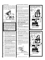
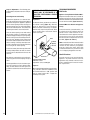
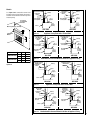
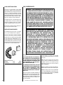
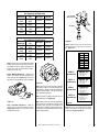
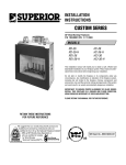
INSTALLATION
INSTRUCTIONS
RETAIN THESE INSTRUCTIONS
FOR FUTURE REFERENCE
This appliance may be installed in an aftermarket permanently located, manufactured home
(USA only) or mobile home, where not prohibited by local codes. This appliance is only for
use with the type of gas indicated on the rating
plate. This appliance is not convertible for use
with other gases, unless a certified kit is used.
For GHC/GRD-5500
WH Report No. J20046562
For GHC/GRD-6500
WH Report No. J20046564
WARNING: IF THE INFORMATION IN THIS MANUAL
IS NOT FOLLOWED EXACTLY, A FIRE OR EXPLOSION MAY RESULT CAUSING PROPERTY DAMAGE, PERSONAL INJURY OR LOSS OF LIFE.
FOR YOUR SAFETY: Do not store or use gasoline
or other flammable vapors or liquids in the vicinity of this or any other appliance.
FOR YOUR SAFETY: What to do if you smell gas:
•
•
•
•
DO NOT light any appliance.
DO NOT touch any electrical switches.
DO NOT use any phone in your building.
Immediately call your gas supplier from a
neighbor’s phone.
Follow your gas suppliers instructions.
• If your gas supplier cannot be reached, call the
fire department.
Installation and service must be performed by a
qualified installer, service agency or the gas
supplier.
B-VENT
GHC-5500/6500 AND
GRD-5500/6500 SERIES
B-VENTED GAS FIREPLACES
P/N 700,027M REV. E 07/2004
MODELS
Millivolt
Models
Electronic
Models
GHC-5500N
GHC-5500P
GRD-5500N
GRD-5500P
GHC-6500N
GHC-6500P
GRD-6500N
GRD-6500P
GHC-5500NE-2
GHC-5500PE-2
GRD-5500NE-2
GRD-5500PE-2
GHC-6500EN
GHC-6500EP
GRD-6500EN
GRD-6500EP
AVERTISSEMENT: ASSUREZ-VOUS DE BIEN SUIVRE
LES INSTRUCTIONS DONNÉ DANS CETTE NOTICE POUR
RÉDUIRE AU MINIMUM LE RISQUE D'INCENDIE OU
POUR ÉVITER TOUT DOMMAGE MATÉRIEL, TOUTE
BLESSURE OU LA MORT.
POUR VOTRE SÉCURITÉ: Ne pas entreposer ni utiliser
d'essence ni d'autre vaperurs ou liquides inflammables
dans le voisinage de cet appareil ou de tout autre
appareil.
POUR VOTRE SÉCURITÉ: Que faire si vous sentez une
odeur de gaz:
• Ne pas tenter d'allumer d'appareil.
• Ne touchez à aucun interrupteur. Ne pas vous servir
des téléphones se trouvant dans le batiment où
vous vous trouvez.
• Evacuez la piéce, le bâtiment ou la zone.
• Appeflez immédiatement votre fournisseur de gaz
depuis un voisin. Suivez les instructions du
fournisseur.
• Si vous ne pouvez rejoindre le fournisseur de gaz,
appelez le service dos incendies.
L'installation et service doit être exécuté par un qualifié
installer, agence de service ou le fournisseur de gaz.
NOTE: DIAGRAMS & ILLUSTRATIONS NOT TO SCALE.
1
TABLE OF CONTENTS
Packaging ........................................ page
Introduction ..................................... page
General Information ......................... page
Location .......................................... page
Appliance Specifications - 5500 ...... page
Appliance Specifications - 6500 ...... page
Venting ............................................ page
Clearances ....................................... page
Framing Specifications .................... page
Typical Installation Sequence .......... page
Pre-Installation Notes ...................... page
Installation ....................................... page
Field Wiring ..................................... page
Connecting Gas Line ........................ page
Outside Air Kit Installation ............... page
Log and Rockwool Installation ........ page
Appliance Operation ........................ page
Millivolt Appliance Checkout ............ page
Electronic Appliance Checkout ......... page
Safety Limit Switch Operation ......... page
Adjustments .................................... page
Finishing Requirements ................... page
Cold Climate Insulation .................... page
Installation Accessories ................... page
Gas Conversion Kits .................. page
2
2
2
3
4
5
6
6
6
7
7
8
9
11
11
12
12
12
13
13
14
14
16
16
16
This installation manual will help you obtain a
safe, efficient, dependable installation for your
appliance and vent system.Please read and
understand these instructions before beginning your installation.
PACKAGING
The assembled vented gas fireplace is packaged with:
1 - one cartoned log set located in firebox area.
2 - one bag of glowing embers (rockwool)
located in the bottom compartment.
3 - one envelope containing the literature
package which consists of the homeowner's
manual, installation instructions, and warranty; envelope is located in the control area.
4 - wall switch for burner operation taped to
top of unit.
INTRODUCTION
The GHC-5500/6500N, P models are circulating system appliances; the GRD-5500/6500N,
P models are radiant heat system appliances;
both types utilize a millivolt gas control valve
and a piezo ignition system. There is no need
for an external power source to operate these
systems. They are designed to operate on
either natural or propane gas.
2
The GHC-5500NE-2, PE-2 and GHC-6500EN,
EP models are circulating system appliances;
the GRD-5500NE-2, PE-2 and GRD-6500EN,
EP models are radiant heat system appliances;
both utilize an electronic gas control valve
along with an intermittent ignition system.
These systems require an external power source
in order to operate. They are designed to operate on either natural or propane gas.
These appliances comply with National Safety
Standards and are tested and listed by Warnock
Hersey (Report No. J20046562 - for 5500
series; J20046564 - for 6500 series models)
to ANSI Z21.50 - 2000 (in Canada, CSA 2.22 2000), and CAN/CGA-2.17-M91 in both USA
and Canada, as vented gas fireplaces.
Installation must conform to local codes. In
the absence of local codes, installation must
comply with the current National Fuel Gas
Code, ANSI Z223.1 (NFPA 54). (In Canada, the
current CAN/CGA B149 installation code.) Electrical wiring must comply with local codes. In
the absence of local codes, installation must
be in accordance with the National Electrical
Code, NFPA 70 - (latest edition). (In Canada,
the current CSA C22.1 Canadian Electric Code.)
DO NOT ATTEMPT TO ALTER OR MODIFY
THE CONSTRUCTION OF THE APPLIANCE OR
ITS COMPONENTS. ANY MODIFICATION OR
ALTERATION MAY VOID THE WARRANTY,
CERTIFICATION AND LISTINGS OF THIS UNIT.
WARNING: IMPROPER INSTALLATION,
ADJUSTMENT, ALTERATION, SERVICE
OR MAINTENANCE CAN CAUSE INJURY
OR PROPERTY DAMAGE. REFER TO THIS
MANUAL. FOR ASSISTANCE OR ADDITIONAL INFORMATION CONSULT A
QUALIFIED INSTALLER, SERVICE
AGENCY OR THE GAS SUPPLIER.
GENERAL INFORMATION
Note: Installation and repair should be performed by a qualified service person. The appliance should be inspected annually by a qualified professional service technician. More frequent inspections and cleanings may be required due to excessive lint from carpeting,
bedding material, etc. It is imperative that the
control compartment, burners and circulating
air passage ways of the appliance be kept clean.
S'assurer que le brùleur et le compartiment des
commandes sont propres. Voir les instructions d'installation et d'utilisation qui
accompagnent l'apareil.
NOTE: DIAGRAMS & ILLUSTRATIONS NOT TO SCALE.
Provide adequate clearances around air openings and adequate accessibility clearance for
service and proper operation. Never obstruct
the front openings of the appliance.
WARNING: THESE FIREPLACES ARE
VENTED DECORATIVE GAS APPLIANCES.
DO NOT BURN WOOD OR OTHER MATERIAL IN THESE APPLIANCES.
These appliances are designed to operate on
natural or propane gas only. The use of
other fuels or combination of fuels will degrade the performance of this system and
may be dangerous.
For elevations of 0-2000 ft. (0-610 m.) the
GHC/GRD-5500 input is 24,000 BTU/HR for
both natural and propane gases, the GHC/
GRD-6500 input is 27,000 BTU/HR for both
natural and propane gases.
Table 1 shows the units' factory-installed
gas orifice size for installations at elevations
of 0-2000 feet (0-610 meters).
GHC
GRD
Series
Orifice size
Nat.
Prop.
5500
#43
#54
6500
#41
#53
Elevation
Feet
(meters)
0-2000
(0-610)
Table 1
Table 2 shows the units' gas orifice size for
installations at elevations greater than 2000 ft.
(0-610 m.). These orifices must be ordered
separately using the kit numbers listed in table 2.
GHC
GRD
Series
Orifice size
(Kit Number)
Nat.
Prop.
5500
#44
(040611)
#55
(040612)
6500
#43
(051916)
#55
(051917)
Elevation
Feet
(meters)
greater
than
2000
(610)
Table 2
Nominal operating pressures for the manifold
side of the gas control system are; 3.5 inches
water column (6.54 MmHg) for natural gas
models and 10 inches water column (18.69
MmHg) for propane gas models.
Do not use these appliances if any part has been
under water. Immediately call a qualified, professional service technician to inspect the appliance and to replace any parts of the control
system and any gas control which have been
under water.
These appliances must not be connected to a
chimney or flue serving a separate solid fuel
burning appliance.
Ne pas se servir de cet appareil s'il a été plongé
dans l'eau, complètement ou en partie. Appeler
un technicien qualifié pour inspecter l'appareil et
remplacer toute partie du système de contrôle et
toute commande qui ont été plongés dans l'lau.
WARNING: FAILURE TO COMPLY WITH
THE INSTALLATION AND OPERATING INSTRUCTIONS PROVIDED IN THIS DOCUMENT WILL RESULT IN AN IMPROPERLY
INSTALLED AND OPERATING APPLIANCE, VOIDING ITS WARRANTY. ANY
CHANGE TO THIS APPLIANCE AND/OR
ITS OPERATING CONTROLS IS DANGEROUS. IMPROPER INSTALLATION OR USE
OF THIS APPLIANCE CAN CAUSE SERIOUS INJURY OR DEATH FORM FIRE,
BURNS, EXPLOSION OR CARBON MONOXIDE POISONING.
This appliance may be installed in an aftermarket permanently located, manufactured home (USA only) or mobile home,
where not prohibited by local codes. This
appliance is only for use with the type of
gas indicated on the rating plate. This appliance is not convertible for use with
other gases, unless a certified kit is used.
Cet appareil peut être installé dans un
maison préfabriquée (É.-U. seulement)
ou mobile déjà installée à demeure si
les réglements locaux le permettent.
Cet appareil doit être utilisé uniquement
avec les types de gaz indiqués sur la
plaque signalétique. Ne pas l'utiliser
avec d'autres gaz sauf si un kit de conversion certifié est installé.
Millivolt appliances may be fitted at time of
manufacture with either a Robertshaw millivolt
gas control valve or Robertshaw electronic gas
control valve. Both valves have been tested
with and approved for use with these appliances and are listed accordingly.
A ¹⁄₈" NPT test gage connection is provided on
either gas control valve adjacent to the outlet to
the main burner.
Minimum inlet gas pressure to the appliance is
4.5 inches water column (1.12 kPa) for natural
gas and 11 inches water column (2.74 kPa) for
propane for the purpose of input adjustment.
Maximum inlet gas supply pressure to the
appliance is 10.5 inches water column (2.61
kPa) for natural gas and 13.0 inches water
column (3.23 kPa) for propane.
The appliance must be isolated from the gas
supply piping system (by closing its individual
manual shut-off valve) during any pressure testing of the gas supply piping system at test
pressures equal to or less than ¹⁄₂ psig (3.5) kPa).
The appliance and its individual shut-off valve must
be disconnected from the gas supply piping system
during any pressure testing of that system at pressures in excess of ¹⁄₂ psig (3.5 kPa).
Do not place clothing or other materials on or
near this appliance.
AVERTISSEMENT: SURVEILLER LES
ENFANTS. GARDER LES VÊTEMENTS,
LES MEUBLES, L'ESSENCE OU AUTRES
LIQUIDES À VAPEUR INFLAMMABLES
LIN DE L'APPAREIL.
WARNING: THIS APPLIANCE MAY ONLY
BE FITTED WITH DOORS CERTIFIED FOR
USE WITH THE APPLIANCE.
AVERTISSEMENT: POUR UTILISATION
UNIQUEMENT AVEC LES PORTES EN
VERRE CERTIFIÊES AVEC L'APPAREIL.
These appliances are equipped with an integral combustion air door and actuator arm.
Combustion air kits are optional. Install as
shown in step 7 on page 11.
LOCATION
Carbon Monoxide Poisoning: Early signs of
carbon monoxide poisoning are similar to the
flu with headaches, dizziness and/or nausea. If
you have these signs, obtain fresh air immediately. Turn off the gas supply to the appliance
and have it serviced by a qualified professional, as it may not be operating correctly.
WARNING: B-VENT APPLIANCES ARE NOT
DESIGNED TO OPERATE IN NEGATIVELY
PRESSURED ENVIRONMENTS (PRESSURE
WITHIN THE HOME IS LESS THAN PRESSURES OUTSIDE). SIGNIFICANT NEGATIVELY PRESSURED ENVIRONMENTS
CAUSED BY WEATHER, HOME DESIGN,
OR OTHER DEVICES MAY IMPACT THE
OPERATION OF THESE APPLIANCES.
NEGATIVE PRESSURES MAY RESULT IN
POOR FLAME APPEARANCE, SOOTING,
DAMAGE TO PROPERTY AND/OR SEVERE
PERSONAL INJURY. DO NOT OPERATE
THESE APPLIANCES IN NEGATIVELY PRESSURED ENVIRONMENTS.
Typical Locations
Figure 1
In selecting the location, the aesthetic and functional use of the appliance are primary concerns.
However, vent system routing to the exterior and
access to the fuel supply are also important. Due
to high temperatures the appliance should be
located out of traffic and away from furniture and
draperies. Consideration should be given to traffic ways, furniture, draperies, etc., due to elevated surface temperatures. The location should
also be free of electrical, plumbing or other
heating/air conditioning ducting.
WARNING: CHILDREN AND ADULTS
SHOULD BE ALERTED TO THE HAZARDS
OF HIGH SURFACE TEMPERATURES. USE
CAUTION AROUND THE APPLIANCE TO
AVOID BURNS OR CLOTHING IGNITION.
YOUNG CHILDREN SHOULD BE CAREFULLY SUPERVISED WHEN THEY ARE IN
THE SAME ROOM AS THE APPLIANCE.
The appliance should be mounted on a fully
supported base extending the full width and
depth of the unit. The appliance may be located
on or near conventional construction materials.
However, if installed on combustible materials,
such as carpeting, vinyl tile, etc., a metal or wood
barrier covering the entire bottom surface must
be used.
WARNING: DO NOT PLACE CLOTHING
OR OTHER FLAMMABLE MATERIALS
ON OR NEAR THIS APPLIANCE.
These appliances may be used for bedroom
installations in the United States and are listed
accordingly. These units may not be installed
in bedrooms in Canada.
NOTE: DIAGRAMS & ILLUSTRATIONS NOT TO SCALE.
3
APPLIANCE SPECIFICATIONS GHC/GRD-5500
GHC-5500
GRD-5500
4 ¹⁄₄"
(108 mm)
4 ¹⁄₄"
(108 mm)
6 ¹⁄₂"
(165 mm)
21"
(533 mm)
33 ¹⁄₄"
(845 mm)
34 ¹⁄₂"
(876 mm)
34 ¹⁄₂"
(876 mm)
21"
(533 mm)
1 ¹⁄₂"
(38 mm)
33 ¹⁄₄"
(845 mm)
7"
(178 mm)
35 ⁷⁄₈" (911 mm)
35 ⁷⁄₈" (911 mm)
Front View
Front View
Gas Inlet
Line
Combustion
Air Inlet
10 ¹⁄₂"
(267 mm)
38 ³⁄₄"
(984 mm)
10 "
(254 mm)
9 ¹⁄₂"
(241 mm)
4 ¹⁄₂"
(114 mm)
8 ¹⁄₂"
(216 mm)
8 ¹⁄₂"
(216 mm)
16" (406 mm)
16" (406 mm)
Left View
Right View
Gas Inlet
Line
Combustion
Air Inlet
38 ³⁄₄"
(984 mm)
4 ¹⁄₂"
(114 mm)
8 ¹⁄₂"
(216 mm)
8 ¹⁄₂"
(216 mm)
15" (381 mm)
15" (381 mm)
Left View
Right View
Top Spacers (4)
Top Spacers (4)
27 ³⁄₄" (705 mm)
27 ³⁄₄" (705 mm)
6 ¹⁄₂"
(165 mm)
6 ¹⁄₂"
(165 mm)
15 "
(381 mm)
1"
(25.4 mm)
15 "
(381 mm)
1"
(25.4 mm)
35 ⁷⁄₈" (911 mm)
35 ⁷⁄₈" (911 mm)
Top View
Top View
Figure 2
4
9"
(229 mm)
NOTE: DIAGRAMS & ILLUSTRATIONS NOT TO SCALE.
APPLIANCE SPECIFICATIONS GHC/GRD-6500
GHC-6500
GRD-6500
4 ¹⁄₄"
(108 mm)
4 ¹⁄₄"
(108 mm)
6 ³⁄₈"
(162 mm)
6 ¹⁄₂"
(165 mm)
21 ¹⁄₂"
(546 mm)
21"
(533 mm)
32" (813 mm)
21"
(533 mm)
16 ¹⁄₄"
(413 mm)
36 ¹⁄₄"
(921 mm)
37 ³⁄₄" (959 mm)
32" (813 mm)
37 ³⁄₄" (959 mm)
39 ⁷⁄₈" (1013 mm)
1 ¹⁄₂"
(38 mm)
¹⁄₂"
(13 mm)
Spacer
8 ³⁄₄"
(222 mm)
Combustion
Air Inlet
7 ¹⁄₂"
(191 mm)
10 ¹⁄₂"
(267 mm)
36 ¹⁄₄"
(921 mm)
16 ¹⁄₄"
(413 mm)
40 ⁵⁄₈" (1032 mm)
40 ⁵⁄₈" (1032 mm)
Front View
Front View
Nailing
Flange
Nailing
Flange
Gas Inlet
Line
¹⁄₂"
(13 mm)
Spacer
Combustion
Air Inlet
40 ¹⁄₂"
(1029 mm)
7 ¹⁄₂"
(191 mm)
6 ¹⁄₂"
(165 mm)
4 ¹⁄₈"
(105 mm)
6 ¹⁄₂"
(165 mm)
¹⁄₂"
(13 mm)
Spacer
5"
(127 mm)
5"
(127 mm)
10 ¹⁄₂"
(267 mm)
Nailing
Flange
Nailing
Flange
Gas Inlet
Line
40 ¹⁄₂"
(1029 mm)
6 ¹⁄₂"
(165 mm)
4 ¹⁄₈"
(105 mm)
6 ¹⁄₂"
(165 mm)
5"
(127 mm)
5"
(127 mm)
20" (508 mm)
17 ⁷⁄₈"
(454 mm)
19" (483 mm)
17 ⁷⁄₈"
(454 mm)
Left View
Right View
Left View
Right View
Top Spacers (4)
Top Spacers (4)
31" (787 mm)
31" (787 mm)
7 ³⁄₄"
(197 mm)
¹⁄₂"
(13 mm)
Spacer ¹⁄₂"
(13 mm)
7 ³⁄₄"
(197 mm)
17 ⁷⁄₈"
(454 mm)
1"
(25.4 mm)
40 ⁵⁄₈" (1032 mm)
¹⁄₂"
(13 mm)
Spacer
¹⁄₂"
(13 mm)
Spacer ¹⁄₂"
(13 mm)
⁵⁄₈"
(16 mm)
1 ⁵⁄₈"
(41 mm)
17 ⁷⁄₈"
(454 mm)
40 ⁵⁄₈" (1032 mm)
Top View
Top View
Figure 3
NOTE: DIAGRAMS & ILLUSTRATIONS NOT TO SCALE.
5
APPLIANCE CLEARANCES
Venting
Gas Vent Rule – Gas vent caps are not permitted
within 8 feet (2.4 mm) of a vertical wall or similar
obstruction. Gas vent caps that are located 8' or
more from a portion of a building which extends
at an angle greater than 45° upward from the
horizontal may terminate in accordance with the
table in Figure 4, provided that in no case shall
any discharge opening on the cap be less than 2'
(610 mm) horizontally from the roof surface
(National Fuel Gas Code ANSI Z223.1 (NFPA 54)
7.6.2) (CAN/CGA B149).
GHC/GRD-5500
GHC/GRD-6500
1/2 in. (13mm)
1/2 in. (13mm)
0 in. (0 mm) to spacers
1/2 in. (13mm)**
1/2 in. (13mm)**
0 in. (0 mm) to spacers
Back
Sides
Top Spacers
0 in. (0 mm)
Floor
0 in. (0 mm)
*From
Bottom of
Unit to
Ceiling
65 1/2 in. (1664 mm)
Vent
X
67 1/2 in. (1715 mm)
1 in. (25.4 mm)
12
SERVICE CLEARANCE
Roof Pitch is X/12
Front
3 Feet (0.9 meters)
* Note: See also Figure 32 on page 14 for an illustration of this clearance, for
Minimum Height from Roof
to Lowest Discharge Opening
clearances to a sidewall and for mantel clearances.
**Note: The nailing tabs and the area directly behind the nailing tabs are exempt
from the clearances described in the above table. See Figure 9 on page 8.
Table 3
Roof Slope
Minimum Height
from Roof to Lowest
Discharge Opening
Feet
FRAMING SPECIFICATIONS
Use Only 2x4 or Larger
Lumber
Meters
Flat to 6/12
1' 0"
0.3
Over 7/12 to 9/12
2' 0"
0.6
Over 10/12 to 12/12
4' 0"
1.2
Over 13/12 to 16/12
6' 0"
1.8
Over 17/12 to 21/12
8' 0"
2.4
Note: If the Outside Combustion
Air Kit is to be installed, it must
be installed before the appliance
is framed and enclosed in the
finishing walls.
B
Note: Venting terminals shall not be recessed
into a wall or siding.
Header
E
Gas Supply Line
Left or Right Side - 5500
Right Side Only - 6500
Figure 4
D
A
*C
*Note: The framed depth - dimension “C”- from a framed wall, must always
be measured from a finished surface. If a wall covering such as drywall is to
be attached to the rear wall, then dimension “C” must be measured from the
drywall surface. It is important that this dimension be exact.
Model No.
GHC/GRD-5500
GHC/GRD-6500
Figure 5
6
A
B
C
D
E
in.
33 1/4
38 3/4
15 1/2
8 1/2
8 1/2
mm
845
984
394
216
216
in.
40 3/4
40 3/4
18
6 1/2
5
mm
1035
1035
457
165
127
NOTE: DIAGRAMS & ILLUSTRATIONS NOT TO SCALE.
TYPICAL INSTALLATION SEQUENCE
FRAMING SPECIFICATIONS CONTINUED
Optional FOAK-4
or FOAK-4LD
Outside Air Kit
Back Wall of Chase/Enclosure
Including Finishing Materials,
If Any.
Note: If the Outside Combustion
Air Kit is to be installed, it must
be installed before the appliance
is framed and enclosed in the
finishing walls.
C
The typical sequence of installation follows,
however, each installation is unique resulting
in variations to those described.
1. Construct the appliance framing.
D
2. Route gas supply line to appliance location.
3. Position the appliance.
4. Install the vent system and exterior termination.
B
A
Square Housing Not
Used on 5500 Model
Rough Framing Face
(Unfinished Shown)
Model No.
A
GHC/GRD-5500
GHC/GRD-6500
5. Field wire and install operating control switch.
Install optional Forced Air Kit, if required
B
C
6. Make connection to gas supply.
D
in.
57 1/2
36
40 3/4
29
mm
1461
914
1035
737
in.
65 3/4
40 3/4
46 1/2
32 7/8
mm
1670
1035
1181
835
7. Install optional Outside Combustion Air Kit,
if required.
8. Install the logs and rockwool.
9. Install the optional glass doors/enclosure
panel, if required
Corner Installation
Figure 6
10. Checkout appliance operation.
Note: If the Outside Combustion
Optional FOAK-4 or FOAK-4LD
Air Kit is to be installed, it must
Outside Air Kit
be installed before the appliance
is framed and enclosed in the
Back Wall of Chase/Enclosure
Including Finishing Materials, If Any. finishing walls.
Model No.
B
GHC/GRD-5500
A
4 IN.
(103 MM)
Square Housing Not
Used on 5500 Model
GHC/GRD-6500
4 IN.
(103 MM)
11. Spillage Test and Safety Limit Switch
Operation.
A
B
in.
36
15 1/2
mm
914
394
in.
40 3/4
18
mm
1035
457
A
B
36
15 1/2
Rough
Framing Face
(Unfinished Shown)
Inside Chase Installation
Figure 7
Optional FOAK-4
or FOAK-4LD
Outside Air Kit
Back Wall of Chase/Enclosure
Including Finishing Materials, If Any.
Note: If the Outside Combustion
Air Kit is to be installed, it must
be installed before the appliance
is framed and enclosed in the
finishing walls.
Model No.
B
GHC/GRD-5500
GHC/GRD-6500
A
Square Housing Not
Used on 5500 Model
in.
mm
914
394
in.
40 3/4
18
mm
1035
457
Rough
Framing Face
(Unfinished Shown)
Outside Chase Installation
12. Adjust burner to ensure proper flame
appearance.
PRE-INSTALLATION NOTES
The fireplace may be installed directly on a
combustible floor or raised on a platform of an
appropriate height. Do not place fireplace on
carpeting, vinyl or other soft floor coverings. It
may, however, be placed on flat wood, plywood, particle board or other hard surfaces,
extending the full depth and width of the appliance. Be sure fireplace rests on a solid continuous floor or platform with appropriate framing
for support and so that no cold air can enter the
room from under the fireplace.
The fireplace may be positioned and then the
framing built around it, or the framing may be
constructed and the fireplace positioned into
the opening.
Usually, no special floor support is needed for
the fireplace, however, to be certain:
1. Estimate the total weight of the fireplace
system and surround materials such as brick,
stone, etc., to be installed.
Figure 8
NOTE: DIAGRAMS & ILLUSTRATIONS NOT TO SCALE.
7
2. Measure the square footage of the floor
space to be occupied by the system, surrounds
and hearth extensions.
IMPORTANT: HOLD GAS VALVE SECURELY
TO PREVENT MOVEMENT WHEN CONNECTING TO INLET GAS LINE
See Figure 11 for 5500 series units and
Figure 12 for 6500 series. Then install the
remainder of the Type B vent to the outside.
3. Note the floor construction, i.e. 2 x 6’s, 2 x
8’s or 2 x 10’s, single or double joists, type and
thickness of floor boards.
WARNING: CONNECTING DIRECTLY TO
AN UNREGULATED PROPANE (L.P.G.)
TANK MAY CAUSE AN EXPLOSION.
Minimum overall height of the vent system and
appliance must be 12' (3.7 m). See Figure 13.
4. Use this information and consult your local
building code to determine if you need additional support.
If you plan to raise the fireplace and hearth
extension, build the platform assembly then
position fireplace and hearth extension on top.
Secure the platform to the floor to prevent
possible shifting.
INSTALLING THE FIREPLACE
Step 1. Construct the Appliance Framing Frame appliance enclosure as illustrated in
Figures 5 through 8 on page 6 and 7.
(Note: Appliance may be positioned first and
then the framing constructed around it.)
Step 3. Position the Appliance - Slide the
fireplace into prepared framing.
(Note: Appliance may be positioned first and
then the framing constructed around it.)
Maximum overall height of the vent system and
appliance should not exceed 40 feet (12.19 m).
Install the B-vent system in accordance with
the vent manufacturer's instructions.
5 in.
Type B-Vent
Fireplace should be secured to side framing
members using the full length ¹⁄₂ inch nailing
flanges that are integral to the appliance at
each side. Use 8d nails (Figure 9 ).
Flue Collar
Assembly
Securing
Screws
Note: The nailing tabs and the area directly
behind the nailing tabs are exempt from the
clearances described on the fireplace clearance label.
If the appliance is to be elevated above floor level,
a solid continuous platform must be constructed.
Flue Outlet
Collar
Figure 11
IMPORTANT: UNDER NO CIRCUMSTANCES
CAN THE FIREPLACE TOP SPACERS (FIGURE
2 OR 3 ) BE REMOVED OR MODIFIED, NOR
MAY YOU NOTCH THE HEADER TO FIT
AROUND OR BE INSTALLED LOWER THAN
THE SPACERS. THE HEADER MAY BE IN DIRECT CONTACT WITH THE TOP SPACERS
BUT MAY NOT BE SUPPORTED BY THEM.
5500 Series Models
Type B Vent
Flue Outlet
Collar
8d Nail
Securing
Screws
Consult all local codes.
Step 2. Route Gas Supply Line - Route gas
line (Figure 5 ) using techniques and materials
prescribed by local and/or national codes. It is
recommended that a gas line of ¹⁄₂" or greater
diameter be used to allow full gas volume to
the fireplace. Undue pressure loss will occur if
the pipe is too small.
Figure 9
Figure 12
Fireplace may be anchored to floor. Bend down
four (4) anchor tabs located at the base of the
fireplace and secure to the floor by nailing with
8d nails (Figure 10 ).
The gas line should extend a total of 2 in.
(51 mm) maximum into the appliance control compartment.
Anchor
Tab
6500 Series Models
CAUTION: THIS APPLIANCE CANNOT BE
VENTED HORIZONTALLY.
Note: Refer to the vent manufacturers installation instructions for variations of venting techniques. If common venting of several units is
contemplated, it should be discussed with an
architect and the local Building Department.
When rigid pipe is used, an ANSI approved
manual shut-off valve and union must be installed upstream of the fireplace.
Ensure that a sediment trap is installed in the
existing gas line, if not, install a sediment trap
upstream to prevent moisture and contaminants
from passing through trap to the appliance controls and burners. Failure to do so could prevent
the appliance from operating reliably.
An external regulator must be used on all propane (L.P.G.) heaters to reduce the supply tank
pressure to 13" w.c. (maximum). Any copper
tubing used to supply propane (L.P.G.) from
the tank must be internally tinned.
8
12 ft.
Minimum
Figure 10
Step 4. Install the Vent System & Exterior
Termination Connect a 5 in. (127 mm) Type B vent system to
the appliance flue collar with four, No. 8 or larger,
sheet metal screws.
Figure 13
NOTE: DIAGRAMS & ILLUSTRATIONS NOT TO SCALE.
Control Compartment Access - GRD Units
5500 Series units
The lower control compartment access panel
has been designed to cover the control compartment from view. To attach the panel to the
appliance, hook both ends of the panel over the
two brackets mounted on each side of the front
combustion opening. The cover should hang
from the brackets with the flared edge at the
bottom allowing for a small air gap between the
cover and the appliance.
6500 Series units
The lower control compartment access panel is
attached to each side of the fireplace by pins
that engage locking slots on the sides of the
panel (Figure 14 ). To remove the panel push in
on it’s top edge with both thumbs, one on each
end of the panel. When the bottom edge of the
access panel swings out, cup it with the finger
tips of both hands. Lift with the finger tips,
moving the panel up and into the appliance. Pull
the panel top edge out from the appliance with
the thumbs to remove it from the lower compartment opening.
Louver Pegs
Louvers
Figure 15
Note: The supplied 18 feet of 2 conductor wire
has one end of each conductor connected to the
gas valve circuit and the other end of each
conductor placed loose on top of the unit.
3 - Install the provided “J” box plate on the “J” box
within the control compartment using the screw
and washer provided with the plate.
4 - Refer to Figure 17 and 18 and the installation instructions provided with the forced
air kit(s) for blower connections to the
appliance recepacle and ground.
5 - Locate and install the millivolt wall switch
(supplied) in a desired location and connect it to the millivolt circuit using the 18 ft
of 2 conductor wire supplied with the unit
(See Figure 16).
Note: The supplied 18 feet of 2 conductor
wire has one end of each conductor connected to the gas valve circuit and the
other end of each conductor placed loose
on top of the unit.
6 - After wiring is complete, replace the appliance junction box cover into the side access opening, from which it was removed,
and secure with the hex head screw previously removed.
LEGEND
TH
TP
Limit Switch
NOTES:
1. If any of the original wire as
supplied with the appliance
must be replaced, it must be
replaced with Type AWM 105°C
- 18 GA wire or equivalent.
TP
Line
Voltage
TH
Thermopile
2. Motor is thermally overloaded
protected.
3. 120V 60 Hz – Less than 3
amps.
1
Blower Motor
ON/OFF Wall Switch
Figure 16
Grounded to
Appliance
CAUTION: DO NOT WIRE THE MILLIVOLT REMOTE WALL SWITCH TO THE MAIN POWER
SUPPLY.
Motor Plug
2
Figure 14
Control Compartment Access - GHC Units
The GHC lower control compartment access is
provided by removing the three louvers (5500
series units) or four louvers (6500 series units).
To remove the louvers, pull them straight out
from the unit. To replace, tilt each of them with
the top edge over the top of each peg and snap
the lower edge to lock in place. See Figure 15.
Step 5. Field Wiring
A. Millivolt Wiring
Millivolt Wiring (Without Forced Air Kit Usage) –
The control tray has been set in place and has
been pre-wired at the factory. All that is required, regarding wiring, is to locate and install
the wall switch (supplied) in a desired location
and connect it to the millivolt circuit using the
18 ft of 2 conductor wire supplied with the unit
(Figure 16 ).
Millivolt Wiring (With Forced Air Kit Usage) –
GHC-5500 series models may use the optional
FAB-1500 or FAB-1600 Forced Air Kit; GHC6500 the FAB-1600 Kit.
Receptacle
120V
Appliance Junction Box
If an optional forced air kit is to be installed now
or sometime in the future, the appliance must be
connected to the main power supply at this time.
1 - Remove the junction box cover from the
outside right bottom corner of the unit by
removing the hex head screw. The junction
box cover has a ⁷⁄₈ in. (22 mm) knockout
hole for a conduit bushing.
2 - Route a 3 wire 120V 60Hz power supply
line through a wall switch to the junction
box and connect the ground wire to the
junction box ground screw, and the black
and white supply wires to the appliance
recptacle as shown in Figure 17.
NOTE: DIAGRAMS & ILLUSTRATIONS NOT TO SCALE.
ON/OFF Blower
Wall Switch
To Fuse
or Circuit
Breaker
Black
}
Receptacle
120V
AC
60Hz
White
Green Ground Screw
Appliance Junction Box
Factory Supplied
Not Supplied
Forced Air Kit Wiring
Millivolt System
Figure 17
9
10
W
BK
GND
Green
Ground
Screw
GHC Series Only
R
BK
W
Ignitor
Junction Box
BK
W
Transf.
120 V.
R
GND
Gas Valve
M
C
P
24 V
BL
BK
BL
W
IGN
PV
TR
GND
BK
Ignition Control
Factory Wired
Field Wired
Electronic System Wiring
(Without Forced Air Kit)
Figure 20
GHC-5500/6500
Robertshaw Ignition Control Equipped
1. If any of the original wire as supplied must be replaced,
1. it must be replaced with Type AWM 105°C – 18 GA. wire.
2. 120V, 60Hz – Less than 3 amps.
LIMIT SW
ON/OFF SW
WALL BLOWER SW
120 VAC
BK
BK
W
24V
LOW
VOLTAGE
Appliance
Ground
Screw
GND
BK
Green
Ground
Screw
Opt
Blower
W
R
BK
Transf.
120 V.
GND
Gas Valve
M
C
P
R
BK
BL
Ignitor
Junction Box
BK
W
24 V
BL
W
IGN
PV
BK
TR
Electronic Wiring (Without Forced Air Kit Usage)
1 - Remove the junction box cover from the
outside right bottom corner of the unit by
removing the hex head screw. The junction
box cover has a ⁷⁄₈ in. (22 mm) knockout
hole for a conduit bushing.
2 - Route a 3 wire 120V 60Hz power supply line
through a wall switch to the junction box and
connect the ground wire to the junction box
ground screw, and the black and white
supply wires to the appliance recptacle as
shown in Figures 18, 19; and 20
(Robertshaw Ignition Module) or 22
(Honeywell Ignition Module).
3 - Install the provided “J” box plate on the “J”
box within the control compartment using
the screw and washer provided with the
plate.
4 - Locate and install the low voltage wall switch
(supplied) in the desired location and connect it to the low voltage circuit using the 18
ft of 2 conductor wire supplied with the unit
as shown in Figure 20.
Note: The supplied 18 feet of 2 conductor
wire has one end of each conductor connected to the gas valve circuit and the
other end of each conductor placed loose
on top of the unit.
5- After wiring is complete, replace the appliance
junction box cover into the side access opening, from which it was removed, and secure
with the hex head screw previously removed.
24V
LOW
VOLTAGE
GND
IMPORTANT: Ground lead must be connected
to the green screw located on the junction
box. See Figure 17, 20, 21, or 22. Failure to
do so will result in a potential safety hazard.
The appliance must be electrically grounded
in accordance with local codes or, in the
absence of local codes, the National Electrical Code, ANSI/NFPA 70-(latest edition). (In
Canada, the current CSA C22-1 Canadian
Electrical Code.)
BK
TH
GHC-5500/6500
If an optional forced air kit is to be installed now
or sometime in the future, the appliance must be
connected to the main power supply at this time.
1 - Remove the junction box cover from the
outside right bottom corner of the unit by
removing the hex head screw. The junction
box cover has a ⁷⁄₈ in. (22 mm) knockout
hole for a conduit bushing.
2 - Route a 3 wire 120V 60Hz power supply
line through a wall switch to the junction
box and connect the ground wire to the
junction box ground screw, and the black
and white supply wires to the appliance
recptacle as shown in Figure 18; and 21
(Robertshaw Ignition Module) or 22
(Honeywell Ignition Module).
Note: If a Honeywell ignition control
module is being used, refer to Figure 22
for the control wiring and Figure 21 for
the blower wiring.
3 - Install the provided “J” box plate on the “J”
box within the control compartment using
the screw and washer provided with the
plate.
4 - Refer to Figure 18 and 21 and the installation instructions provided with the forced
air kit(s) for blower connections to the
appliance receptacle and ground.
5 - Locate and install the low voltage wall
switch (supplied) in a desired location and
connect it to the millivolt circuit using the
18 ft of 2 conductor wire supplied with the
unit (See Figure 21).
Note: The supplied 18 feet of 2 conductor
wire has one end of each conductor connected to the gas valve circuit and the
other end of each conductor placed loose
on top of the unit.
6 - After wiring is complete, replace the appliance junction box cover into the side access opening, from which it was removed,
and secure with the hex head screw previously removed.
120 VAC
ON/OFF SW
PV/MV
Figure 18
LIMIT SW.
PV/MV
Electronic
Millivolt
Blower
Note: “J” box plates are not affixed in place at the factory.
1. If any of the original wire as supplied must be replaced,
1. it must be replaced with Type AWM 105°C – 18 GA. wire.
2. 120V, 60Hz – Less than 3 amps.
MV
Optional
Blower
GHC-5500 series models may use the optional
FAB-1500 or FAB-1600 Forced Air Kit; GHC6500 the FAB-1600 Kit.
GHC/GRD-5500/6500
Robertshaw Ignition Control Equipped
TH
Transformer
Electronic Wiring (With Forced Air Kit Usage) –
MV
B. Electronic Wiring
Note: These appliances may be equipped with
either of two ignition control modules:
Robertshaw or Honeywell. The Robertshaw
module wiring is shown in Figures 20 and 21;
the Honeywell, in Figure 22.
Ignition Control
Electronic
120V Receptacle
Note: “J” box plate is not affixed in place at the factory.
Figure 19
GRD-5500/6500
NOTE: DIAGRAMS & ILLUSTRATIONS NOT TO SCALE.
Factory Wired
Field Wired
Electronic System Wiring
(With Forced Air Kit)
Figure 21
Gas Flex Line Connector
GHC/GRD-5500/6500
(Honeywell Ignition Module Equipped)
Gas
Valve
³₈" NPT x ³₈"
Flare Fitting
1. If any of the original wire as supplied must be replaced,
1. it must be replaced with Type AWM 105°C – 18 GA. wire.
2. 120V, 60Hz – Less than 3 amps.
LIMIT SW
³₈" Flex Tubing
ON/OFF SW
³₈" Shut-Off Valve
NEU. W
BK
120 VAC. BK
GND
24V
Low Voltage
³₈" Nipple
³₈" Union
³₈" Close Nipple
Green
Ground
Screw
R
³₈" Flare x ¹₂" NPT
Shut-Off Valve
W
Gas Stub
³₈ " x ¹₂ "
Reducer
BK
Ignitor
Transf.
120 V.
Gas Valve
M
P
C
G
R
BK
W
24 V
BL
BL
Millivolt
Gas Valve
Ignition Control
Factory Wired
If an optional “All-Glass” enclosure panel is to
be installed on the 6500 Series appliances, an
extension bar must be attached to the actuator
lever as illustrated in Figures 26 and 27. Both
versions of the actuator lever extension bar are
packaged with the glass enclosure panel.
Piezo Ignitor
SPARK
TH-W
(OPT.)
24V
GND
24V
PV
W
GND
(Burner)
MV
PV/MV
BK
Field Wired
Electronic System Wiring
(Without Forced Air Kit)
Figure 22
Step 6. Connecting Gas Line –
Make gas line connections. All codes require a shut-off valve mounted in the supply
line. Figure 23 illustrates two methods for
connecting the gas supply. The flex-line
method utilizing the gas flex line provided
with the appliance is acceptable in the U.S.,
however, Canadian requirements vary depending on locality. Installation must be in
compliance with local codes.
The millivolt and electronic control valve have
³⁄₈" (10 mm) NPT thread inlet ports.
WARNING: TO PREVENT DAMAGE TO
THE VALVE AND OTHER ATTACHED COMPONENTS, HOLD VALVE FIRMLY IN
PLACE WHILE TIGHTENING FITTINGS
USED IN THE NEXT STEP.
The gas control valve is located in the lower
control compartment. See Figure 24. To access the valve see page 9, the Control Compartment Access Section.
Figure 24
When outside combustion air is desired, Lennox' Model FOAK-4 or Model FOAK-4LD combustion air kit should be used. Refer to the
installation instructions packed with the air kit
for specific installation information. The outside
air kit must be installed before the appliance is
framed and enclosed in the finished walls.
The control lever, located on the left side of the
appliance front opening, controls the entrance
of combustion air from the outside. See Figure
25 for 5500 series units, Figure 26 for GHC6500 series units or Figure 27 for GRD-6500
series units. The 6500 series units have a cover
over the control lever fastened by one screw.
Remove the screw and then the cover and
discard them.
Figure 23
Junction Box
BK
Step 7. Install Optional Outside
Combustion Air Kit
Location of Controls
Secure all joints tightly using appropriate
tools and sealing compounds (ensure propane resistant compounds are used in propane applications).
Turn on gas supply and test for gas leaks using
a soapy water solution. Never use an open
flame to check for leaks.
Combustion Air Control Lever
A. Mix a 50% dish soap, 50% water solution.
B. Light the appliance (refer to the lighting
instructions provided in the Homeowner's Care
and Operation Instructions).
Figure 25
C. Brush all joints and connections with the
soapy water solution to check for leaks. If
bubbles are formed, or gas odor is detected,
turn the gas control knob to the “OFF” position. Either tighten or refasten the leaking
connection and retest as described above.
D. When the gas lines are tested and leak free,
observe the individual tongues of flame on the
burner. Make sure all ports are open and
producing flame evenly across the burner. If
any ports are blocked, or partially blocked,
clean out the ports.
GHC/GHR-5500 SERIES
Actuator Lever
Phillips Pan
Head Screw
#6-32 x ⁷⁄₃₂"
(6 mm)
C
Extension Bar
O
Combustion Air Control Lever and
Extension on GHC-6500 Series Units
Figure 26
NOTE: DIAGRAMS & ILLUSTRATIONS NOT TO SCALE.
11
Actuator
Lever
Phillips Pan
Head Screw
#6-32 x ⁷⁄₃₂"
(6 mm)
C
Extension Bar
O
Combustion Air Control Lever and
Extension on GRD-6500 Series Units
Figure 27
CAUTION: NEVER LOCATE INLET WHERE IT
CAN BE BLOCKED BY SHRUBS, SNOW DRIFTS,
ETC. NEVER LOCATE INLET IN GARAGE OR
ANY AREA WHERE THERE IS ANOTHER FUEL
BURNING APPLIANCE OR PRODUCTS EMITTING COMBUSTIBLE GASES SUCH AS PAINT,
GASOLINE, ETC. IN COLD CLIMATES, IT IS
RECOMMENDED THE COMBUSTION AIR DUCT
BE INSULATED.
Outside combustion air ducting may be run
upwards or vertically through framing and ceiling joists, with the hood installed through an
outside wall and 3' (1 m) below the B-Vent
termination. Ducting may also be run downward through floor joists and under the home to
a ventilated crawlspace not considered part of
the living area of the home.
Note: Do not terminate combustion air kit in
attic space under any circumstances.
Step 9. Optional Glass Doors/Enclosure Panel
Availablity, Precautions and Instructions –
See the Homeowner's Care and Operating Instructions for a selection of glass doors/enclosure panels available for installation in these
appliances. Installation Instructions for the
doors/enclosure panels are provided with them.
• Never clean glass when doors or panel are
hot due to operating the appliance.
• Glass and metal frames get hot. Use only
the wooden handles to open and close the
doors or to lift out panel.
Note: Lighting instructions are also found on
the pull-out label attached near the gas valve in
the control compartment.
When first lighting the appliance, it will take a
few minutes for the line to purge itself of air.
Once purging is complete, the pilot and burner
will light and operate as indicated in the instruction manual.
Subsequent lightings of the appliance will not
require such purging. Inspect the pilot flame
(remove logs, if necessary, handling carefully).
Millivolt Appliance Checkout
CAUTION: THE APPLIANCE SHOULD ONLY BE
OPERATED WITH THE GLASS DOORS FULLY
OPEN OR FULLY CLOSED.
Rectangular Housing Not Used on
5500 Series Units
Glass Doors
Fully Open or
Fully Closed
(Twin-Pane Doors)
The gas control system on these appliances is
a millivolt standing pilot type. It consists of a
pilot burner, a piezo ignitor, a gas control
valve, a burner assembly and an ON/OFF wall
switch. A temperature limit switch is wired in
series with the millivolt wall switch and gas
control valve. If a higher than normal temperature is sensed due to a blocked vent or prolonged downdraft, the limit switch will open
and cause the burner to shut off.
The pilot flame should be steady, not lifting or
floating. Flame should be blue in color with
traces of orange at the outer edge.
The top ³⁄₈" (9 mm) at the pilot generator
(thermopile) should be engulfed in the pilot
flame (Figure 30 ).
Figure 28
Rectangular Housing Not Used on
5500 Series Units
³⁄₈" (10 mm)
After completing the installation of the optional combustion air vent system the actuator arm must be put in service and tested to
ensure proper operation before completing
any enclosure around the firebox. Failure to
do so may result in extensive and costly
rework.
Operate the actuator through several cycles
including the closed position. Ensuring proper
operation and freedom of movement. Return
the actuator arm to the closed position.
Step 8. Installing Logs and Rockwool –
The logs are packaged within the firebox. The
bag of rockwool is in the lower control compartment. Refer to the Homeowner's Care and
Operating Instructions for detailed placement
instructions for the logs and rockwool.
12
Glass Doors
Fully Open or
Fully Closed
(Bi-Fold Doors)
Figure 29
APPLIANCE OPERATION
Step 10. Checking the System –
Figure 30
With gas line installed, run initial system checkout before closing up the front of the unit.
Follow the pilot lighting instructions provided
in the Homeowner's Care and Operation Instructions. For piezo ignitor location see Figure 24 on page 11 (millivolt appliances only).
If the pilot flame pattern is not as shown in
Figure 30, adjust it as follows:
NOTE: DIAGRAMS & ILLUSTRATIONS NOT TO SCALE.
1. Remove the pilot adjustment cap located on
the main gas valve.
2. Adjust the pilot screw to provide properly
sized pilot flame (Figure 30 ). Turn counter
clockwise to enlarge pilot flame and clockwise
to reduce the pilot flame. DO NOT attempt to
adjust pilot flame more than one half turn.
Manual Reset Limit Switch
3. Replace the pilot adjustment cap.
Replace logs if removed for pilot inspection.
To light the burner; rotate the gas valve control
knob counterclockwise to the “ON” positionand
then turn “ON” the remote wall switch.
Lintel
Extention
Electronic Appliance Checkout
The gas control system on these appliances is
an electronic low voltage gas control valve
with an intermittent ignitor. It consists of a low
voltage gas control valve, an intermittent ignition system, an electronic control module,
transformer and a burner assembly. A temperature limit switch is wired in series with the
gas control valve. If a higher than normal
temperature is sensed, due to a blocked vent
or prolonged downdraft, the limit switch will
open and cause the burner to shut off.
Firebox Wrapper
Limit Switch Screws
Figure 31 (GHC/GRD-5500)
Manual Reset Limit Switch
The pilot flame should be steady, not lifting or
floating. Flame should be blue in color with
traces of orange at the outer edge.
To light the burner, push the gas control lever
in and toward the left to the “ON” position.
Turn ‘ON’ the remote wall switch. Ensure the
ignitor lights the pilot. The pilot flame should
engulf the ignitor.
Step 11. Safety Limit Switch Operation
Limit
Switch
Screws
MANUALLY-RESET BLOCKED FLUE SAFETY
SWITCH
These appliances are equipped with a manually-reset blocked flue safety switch. Refer
to Figures 31 and 32 for their location. If
during appliance operation, the flame goes
out (independently of the burner on/off wall
switch), it may be due to the operation of
the safety limit switch. First allow the
appliance to cool. Then reset the safety
switch by pushing the red reset button on the
back of the switch.
CAUTION: THE ELECTRONIC APPLIANCE
SHOULD BE TURNED OFF BEFORE REMOVING THE LIMIT SWITCH.
Fireplace Front
Lintel Extention
Figure 32 (GHC/GRD-6500)
To access the safety limit switch reset button,
remove the two screws. Pull out limit switch
with low voltage wires attached, push the reset
button, then reinstall the limit switch. At this
time turn the electronic appliance back on.
NOTE: DIAGRAMS & ILLUSTRATIONS NOT TO SCALE.
The appliance should then relight and remain
lit. If this does not occur, turn off the appliance and call a qualified service technician.
13
Step 12. Adjustments – The following paragraphs address adjustment concerns and procedures.
Flame Appearance and Sooting
Proper flame appearance is a matter of taste.
Generally most people prefer the warm glow of
a yellow to orange flame. Appliances operated
with air shutter openings that are too large, or
with long vertical vent runs, will exhibit flames
that are blue and transparent. These weak, blue
and transparent flames are termed anemic.
If the air shutter opening is too small sooting
may develop. Sooting is indicated by black
puffs developing at the tips of very long orange
flames. Sooting results in black deposits forming on the logs, appliance inside surfaces and
on exterior surfaces adjacent to the vent termination. Sooting is caused by incomplete combustion in the flames and a lack of combustion
air entering the air shutter opening.
WARNING: AIR SHUTTER ADJUSTMENT
SHOULD ONLY BE PERFORMED BY A
QUALIFIED PROFESSIONAL SERVICE
TECHNICIAN.
Adjustment
To adjust the flame, position the air shutter to
the nominal setting (Figure 33 ). Allow the
burner to operate for at least 30 minutes.
Observe the flame continuously. If it appears
weak or sooty as previously described, adjust
the air shutter open or closed until desired
effect is achieved.
Orifice
Air Shutter
Adjusting
Set Screw
To achieve a warm yellow to orange flame with
an orange body that does not soot, the shutter
opening must be adjusted between these two
extremes.
No smoke or soot should be present. Reposition the log set if the flames impinge on any of
them.
If sooting conditions exist, the air shutter opening on the main burner can be adjusted. Normally, the more offsets in the vent system, the
greater the need for the air shutter to be opened
further.
14
FINISHING REQUIREMENTS
Wall Details
Appliance Facing Flush with Finished Wall Complete finished interior wall. To install the
appliance facing flush with the finished wall,
position framework to accommodate the thickness of the finished wall (Figure 35 and 37 ).
Surround Materials Relative to Appliance
FacingSurround materials (noncombustible) can
be placed around the appliance facing to
provide a flush surface between the surround materials and the appliance front facing. Do not cover the louvers of the GHC or
the bottom control compartment access on
the GRD. (Figures 36 and 38 ).
Note: Combustible wall finish materials and/or
surround materials must not be allowed to
encroach the area defined by the appliance
front face (black sheet metal). Never allow
combustible materials to be positioned in front
of or overlapping the appliance front face.
Hearth Extensions
Burner Tube
Nominal Air Shutter Settings:
Natural Gas - Closed
Propane Gas - 1/6 in. (1.59 mm) Open
Figure 33
When satisfied that the appliance operates properly, proceed to finish the installation. Leave
the control knob/lever in “ON” position and
turn the remote switch “OFF.” Replace the
refractory access panel.
NOTE: DIAGRAMS & ILLUSTRATIONS NOT TO SCALE.
A hearth extension is not required with this
appliance. Any hearth extension used is for
appearance only and does not have to conform to standard hearth extension installation requirements.
Mantels
Combustible
Finished Wall
See Figure 34 for combustible mantel shelf
projections from the wall and for the mantel's
minimum vertical distance from the top of the
firebox opening.
Framing
Combustible
Mantel
Noncombustible
Covering Wall
Top of
Fireplace
Top of
Fireplace
Opening
GRD-5500
Appliance Facing Flush with a Finished Wall
Figure 35
Combustible Finished
Wall Materials
Combustible
Mantel
Framing
Top of
Fireplace
Noncombustible
Covering Wall
NonCombustible
Surround
GHC/GRD-5500
GHC/GRD-6500
Figure 34
Combustible Finished
Wall Materials
Combustible
Mantel
Framing
Spacer
A
Model No.
Top of
Fireplace
Noncombustible
Covering Wall
GHC-5500
B
Spacer
Top of
Fireplace
Opening
Louvers
Combustible
Mantel
Framing
Spacer
0" Clearance
to Combustible
Side Wall
Max. Projection 8 in. (203 mm)
Combustible
Finished Wall
Combustible
Mantel
A
B
in.
11
65 1/2
mm
279
1664
in.
10
67 1/2
mm
254
1715
Top of
Fireplace
Opening
Spacer
Noncombustible
Covering Wall
Top of
Fireplace
Top of
Fireplace
Opening
NonCombustible
Surround
Louvers
GRD-5500
GHC-5500
Figure 36
NonCombustible Surround Materials Relative to Appliance Facing
Combustible Finished
Wall Materials
Combustible
Mantel
Framing
Combustible Finished
Wall Materials
Framing
Combustible
Mantel
Spacer
Spacer
Top of
Fireplace
Top of
Fireplace
Top of
Fireplace
Opening
Top of
Fireplace
Opening
Louvers
GHC-6500
GRD-6500
Appliance Facing Flush with a Finished Wall
Figure 37
Combustible
Finished Wall
Materials
Combustible
Mantel
Framing
Combustible
Finished Wall
Materials
Combustible
Mantel
Framing
Spacer
Spacer
Top of
Fireplace
Top of
Fireplace
NonCombustible
Surround
Top of
Fireplace
Opening
Louvers
GHC-6500
Figure 38
NonCombustible
Surround
Top of
Fireplace
Opening
GRD-6500
NonCombustible Surround Materials Relative to Appliance Facing
NOTE: DIAGRAMS & ILLUSTRATIONS NOT TO SCALE.
15
COLD CLIMATE INSULATION
GAS CONVERSION KITS
If you live in a cold climate, seal all cracks
around your appliance with noncombustible
material and wherever cold air could enter the
room. It is especially important to insulate
outside chase cavity between studs and under
floor on which appliance rests, if floor is above
ground level.Ensure that the clearance requirements for venting are always maintained.
To avoid air intrusion, surround material must
be caulked where it meets the black metal
facing of the appliance. Only use a noncombustible caulking material to seal this area.
Do not place insulation materials within the 1"
gas vent system clearance space.
INSTALLATION ACCESSORIES
The following accessory items are available
for use in the installation of this appliance.
Outside Air Kits Models FOAK and FOAK-LD
Outside Air kits are available with duct (FOAK4) and without duct (FOAK-4LD) for use if
outside combustion air is required or desired.
If model FOAK-4LD is used it must be used in
conjunction with locally purchased, non-combustible Class 1 or Class 0 flexible duct.
WARNING: THIS CONVERSION KIT SHALL BE INSTALLED
BY A QUALIFIED SERVICE AGENCY IN ACCORDANCE WITH
THE MANUFACTURER'S INSTRUCTIONS AND ALL APPLICABLE CODES AND REQUIREMENTS OF THE AUTHORIZED
AGENCY HAVING JURISDICTION. IF THE INFORMATION IN
THESE INSTRUCTIONS ARE NOT FOLLOWED EXACTLY, A
FIRE, EXPLOSION OR PRODUCTION OF CARBON MONOXIDE MAY RESULT CAUSING PROPERTY DAMAGE, PERSONAL INJURY OR LOSS OF LIFE. THE INSTALLATION IS
NOT PROPER AND COMPLETE UNTIL THE OPERATION OF
THE CONVERTED APPLIANCE IS CHECKED AS SPECIFIED IN
THE OWNER INSTRUCTIONS SUPPLIED WITH THE KIT.
AVERTISSEMENT: CET ÉQUIPEMENT DE CONVERSION
SERA INSTALLÉ PAR UNE AGENCE QUALIFIÉE DE SERVICE CONFORMÉMENT AUX INSTRUCTIONS DU
FABRICANT ET TOUTES EXIGENCES ET CODES
APPLICABLES DE L'AUTORISÉS AVOIR LA JURIDICTION.
SI L'INFORMATION DANS CETTE INSTRUCTION N'EST
PAS SUIVIE EXACTEMENT, UN FEU, EXPLOSION OU PRODUCTION DE PROTOXYDE DE CARBONE PEUT RÉSULTER
LE DOMMAGES CAUSER DE PROPRIÉTÉ, PERTE OU
BLESSURE PERSONNELLE DE VIE. L'AGENCE QUALIFIÉE
DE SERVICE EST ESPONSABLE DE L'INSTALLATION
PROPRE DE CET ÉQUIPMENT. L'INSTALLATION N'EST
PAS PROPRE ET COMPLÉTE JUSQU'À L'OPÉRATION DE
L'APPAREIL CONVERTI EST CHÉQUE SUIVANT LES
CRITÈRES ÉTABLIS DANS LES INSTRUCTIONS DE
PROPRIÉTAIRE PROVISIONNÉES AVEC L'ÉQUIPEMENT.
In Canada
Outside Combustion Air Kits
(with duct)
81L87
(without duct)
81L88
FOAK-4
FOAK-4LD
THE CONVERSION SHALL BE CARRIED OUT
IN ACCORDANCE WITH THE REQUIREMENTS
OF THE PROVINCIAL AUTHORITIES HAVING
JURISDICTION AND IN ACCORDANCE WITH
THE REQUIREMENTS OF THE CAN1-B149.1
AND .2 INSTALLATION CODE.
LA CONVERSION DEVRA ÊTRE EFFECTUÉE
CONFORMÉMENT AUX RECOMMANDATIONS
DES AUTORITÉS PROVINCIALES AYANT
JURIDICTION ET CONFORMÉMENT AUX
EXIGENCES DU CODE D'INSTALLATION CAN1B149.1 ET.2.
Gas conversion kits are available to adapt your
appliance from the use of one type of gas to the
use of another. These kits contain all the necessary components needed to complete the task
including labeling that must be affixed to ensure safe operation.
16
NOTE: DIAGRAMS & ILLUSTRATIONS NOT TO SCALE.
Kit part numbers are listed on the next page
and the following steps detail the conversion
procedure.
Note: These kits contain a main orifice which
can be used for installation at elevations of
0-2000 Ft. (610 m.) For elevations greater
than that, use the correct orifice as shown in
table 2 on page 2.
Step 1. Turn off the gas supply to the appliance.
Open the doors or remove the enclosure panel.
Step 2. Carefully remove the two (5500 Models) or four (6500 Models) smaller logs on top.
Then remove the two (2) main logs. Exercise
care as not to break the logs.
Natural To Propane
Gas Conversion Kit Application
Unit
Kit Model
Unit Type
Models No.
No.
GHC/GRD- GCK-5500millivolt
5500
MNP
GHC/GRD- GCK-6500millivolt
6500
MNP
GHC/GRD- GCK-5500electronic
5500
ENP
GHC/GRD- GCK-6500electronic
6500
ENP
Part No.
Pilot Assembly
(Millivolt Shown)
058092
063431
Pilot Orifice
058061
058069
Propane To Natural
Gas Conversion Kit Applications
Units
Kit Model
Unit Type
Part No.
Models No.
No.
GHC/GRD- GCK-5500millivolt
058072
5500
MPN
GHC/GRD- GCK-6500millivolt
063441
6500
MPN
GHC/GRD- GCK-5500electronic
058051
5500
EPN
GHC/GRD- GCK-6500electronic
058059
6500
EPN
Figure 41
Step 9. Attach conversion kit label to the
rating plate on the appliance as shown in
the Figure 42 .
Step 3. Remove three (3) screws from the back
of the burner tray. Lift the rear of the burner tray
up slightly and to the right to disengage the
burner tube from the manifold and orifice.
Remove the burner tray.
LABEL B
GHC/GRD-5500
Figure 39
Step 5. Electronic Appliances – Mark the
wires to the gas valve and remove the valve
(Figure 40). Replace the valve with the one
provided with the kit.
LABEL E
LABEL C
LABEL F
LABEL G
LABEL J
LABEL H
LABEL K
LABEL I
LABEL L
NATURAL GAS
INPUT BTU/HR – 24,000
MANIFOLD PRESSURE – 3.5"
ORIFICE SIZE #43
THIS APPLIANCE HAS BEEN CONVERTED TO:
LABEL A
Figure 40
Regulator
LABEL D
THIS APPLIANCE HAS BEEN CONVERTED TO:
Step 4. Millivolt Appliances – Remove and
replace the regulator assembly located on the
front of the gas valve (Figure 39 ). Ensure that
the gasket is seated properly and is not kinked.
Gasket
LABEL A
LABEL B
GCH/GRD-6500
NATURAL GAS
INPUT BTU/HR – 27,000
MANIFOLD PRESSURE – 3.5"
ORIFICE SIZE #41
Step 6. Remove the orifice from the manifold
and replace it with the one provided in the kit;
5500 models - #43 for natural gas and #54 for
propane, 6500 models - #41 for natural gas
units and #53 for propane.
GHC/GRD-5500
Step 7. Replace the pilot orifice with the one
provided with the kit (Figure 41).
GHC/GRD-6500
THIS APPLIANCE HAS BEEN CONVERTED TO:
LABEL L
PROPANE/LPG
INPUT BTU/HR – 24,000
MANIFOLD PRESSURE – 10"
ORIFICE SIZE #54
THIS APPLIANCE HAS BEEN CONVERTED TO:
LABEL G
PROPANE/LPG
INPUT BTU/HR – 27,000
MANIFOLD PRESSURE – 10"
ORIFICE SIZE #53
Step 8. Reassemble all removed components
by reversing the procedures outlined in the
preceding steps. Use pipe joint compound or
Teflon tape on all fittings before installing (ensure propane resistant compounds are used in
propane applications).
NOTE: DIAGRAMS & ILLUSTRATIONS NOT TO SCALE.
Figure 42
Step 10. Turn on gas supply and test for gas
leaks as described in the gas line connection
instructions, Step 6 on page 11.
17
18
NOTE: DIAGRAMS & ILLUSTRATIONS NOT TO SCALE.
NOTE: DIAGRAMS & ILLUSTRATIONS NOT TO SCALE.
19
The manufacturer reserves the right to make changes at any time, without notice, in design, materials, specifications, prices and also to discontinue colors, styles and products.
Consult your local distributor for fireplace code information.
Printed in U.S.A. © 2001 by Lennox Hearth Products
20
P/N 700,027M REV. E 07/2004
NOTE: DIAGRAMS & ILLUSTRATIONS NOT TO SCALE.
LHP
1110 West Taft Avenue • Orange, CA 92865