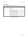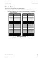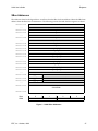
1
S16A SBus 16-bit Dual Analog Interface for the Sun SPARCstation USER’S GUIDE 008-00630-01 EDT S16A User’s Guide The information in this document is subject to change without notice and does not represent a commitment on the part of Engineering Design Team, Inc. The software described in this document is furnished under a license agreement or nondisclosure agreement. The software may be used or copied only in accordance with the terms of the agreement. No part of this manual may be reproduced or transmitted in any form or by any means, electronic or mechanical, without the express written agreement of Engineering Design Team, Inc. Copyright Engineering Design Team, Inc. 1992–1997. All rights reserved. Refer questions or problems with this manual or the hardware or software described herein to: Engineering Design Team, Inc. 1100 NW Compton Drive, Suite 306 Beaverton, Oregon 97006 Phone: (503) 690-1234 Fax: (503) 690-1243 E-mail: [email protected] Web: www.edt.com Sun, SunOS, SBus, SPARC, and SPARCstation are trademarks of Sun Microsystems, Incorporated. UNIX and OPEN LOOK are registered trademarks of UNIX System Laboratories, Inc. X Window System is a product of the Massachusetts Institute of Technology. EDT and Engineering Design Team are trademarks of Engineering Design Team, Inc. ii EDT, Inc. October, 1996 S16A User’s Guide Contents Overview .......................................................................................................................................................................1 Installation.....................................................................................................................................................................2 Installing the Hardware.....................................................................................................................................2 Installing the Software .......................................................................................................................................2 Using SunOS Version 4.1 .........................................................................................................................2 Using System V Release 4 (Solaris 2.4 or Later) ...................................................................................4 Building the Sample Programs ...............................................................................................................4 Included Files ......................................................................................................................................................5 Input and Output .........................................................................................................................................................6 Elements of S16A Applications ........................................................................................................................6 DMA Library Routines ......................................................................................................................................7 Error Conditions ...............................................................................................................................................22 Hardware Interface ....................................................................................................................................................23 Electrical Interface ............................................................................................................................................23 Interface Signals ................................................................................................................................................24 Connector Pinout..............................................................................................................................................25 Registers.......................................................................................................................................................................26 SBus Addresses .................................................................................................................................................27 DMA Registers ..................................................................................................................................................28 Current DMA Address Registers .........................................................................................................28 Next DMA Address Registers...............................................................................................................28 Current Count Registers ........................................................................................................................29 Control and Next Count Registers .......................................................................................................29 Direct I/O Registers .........................................................................................................................................30 DIO Direction Register ...........................................................................................................................30 DIO Data Register ...................................................................................................................................30 DAC Output Control Register ........................................................................................................................30 Analog Input Module Internal Registers ......................................................................................................31 Input Clock Prescale Registers..............................................................................................................32 Input Configuration Registers ..............................................................................................................32 Trim Registers..........................................................................................................................................33 Temperature Register .............................................................................................................................34 Analog Input Module UART Registers.........................................................................................................34 Analog Input Module Control Protocol ..............................................................................................34 UART Command/Status Register........................................................................................................36 UART Data Register ...............................................................................................................................37 Xilinx Programming Registers........................................................................................................................37 Specifications ..............................................................................................................................................................38 References....................................................................................................................................................................39 Contacting EDT ..........................................................................................................................................................40 Index.............................................................................................................................................................................41 EDT, Inc. October, 1996 iii S16A User’s Guide Tables General DMA Library Routines .....................................................................................................................................7 S16A-specific Library Routines......................................................................................................................................8 Error Codes and Conditions ..........................................................................................................................................22 S16A Interface Signals..................................................................................................................................................24 Connector Pinout...........................................................................................................................................................25 DMA Channel Assignments .........................................................................................................................................28 Current DMA Address Registers ..................................................................................................................................28 Next DMA Address Registers.......................................................................................................................................29 Current Count Registers................................................................................................................................................29 Control and Next Count Registers ................................................................................................................................29 DAC Output Control Register.......................................................................................................................................31 Analog Input Module Internal Registers.......................................................................................................................31 Input Selection (Low Byte) Values...............................................................................................................................32 Input Gain (High Byte) Values .....................................................................................................................................33 Trim Registers...............................................................................................................................................................33 UART Command/Status Register .................................................................................................................................36 iv EDT, Inc. October, 1996 S16A User’s Guide Overview Overview The S16A SBus 16-bit Dual Analog Interface is a single-slot board for SBus-based computer systems. The S16A has two analog I/O channels, each incorporating one 16-bit Analog-to-Digital (ADC) converter and one 20-bit Digital-to-Analog (DAC) converter. The S16A is designed for continuous input and output on both channels simultaneously and is typically used for scientific and medical research and development. The S16A employs two Burr-Brown® PCM1702 analog output DACs running at a sample rate of 705.6KHz, which is 16 times the standard audio frequency of 44.1 KHz. The two S16A analog input ADCs are National Semiconductor® ADC16071s, running with a base sampling rate of 192KHz. The S16A provides a clock prescale register to divide this frequency down for lower rates. The S16A uses the SBus DMA interface and can transmit or receive any amount of data to and from host memory continuously on both channels at once. Each I/O channel’s input ADC can monitor a differential signal, either of the two differential inputs as a single-ended signal, either of two I/O channels’ DAC outputs, or a reference ground. The ability to monitor the outputs directly or ground allows the S16A to be tested and adjusted using these internal loop-backs. A portion of the functionality of the S16A is contained in a sub-assembly, the Analog Input Module. This module is controlled and configured using a byte-sequence protocol, as described in the section Analog Input Module Control Protocol beginning on page 34. The S16A boards fully support the requirements of the SunOS operating system. Example programs are included. Each of the two I/O channels appears as two subdevices to the SunOS operating system, one for input and one for output, for a total of four subdevices. This document explains how to install the S16A interface and driver and how to write applications for it. It is divided into the following sections: Installation describes how to install the board and its related software. Input and Output describes the programming interface library. Hardware Interface Protocol provides a connector pin-out diagram and describes the S16A signals and timing. Registers describes the hardware registers. Specifications lists the product specifications. References lists other documentation resources that may be helpful. Contacting EDT describes how to contact EDT, and how to access EDT resources on the Internet. EDT, Inc. October, 1996 1 Installation S16A User’s Guide Installation Installing the S16A SBus 16-bit Dual Analog Interface is a two-step process. First you must physically install the board inside the host computer. Then you must install the software driver so that applications can access the S16A. Hardware installation is described in the following section. Software installation is described in the section after. Installing the Hardware The S16A board is a single-slot SBus board. To install it, refer to your SBus host computer documentation for complete information on installing an SBus board. For example, many Sun systems contain this information in a manual entitled SPARCstation Installation Guide. Use the following procedure to install the SBus 16-bit Dual Analog Interface: CAUTION Both the S16A and your SBus host computer contain static-sensitive components. Install the S16A at a static-free work area. If a static-free work area is not available, take the following precautions to reduce the risk of component damage: 1. Remove from the immediate area all materials that can generate or hold a static charge. 2. Discharge yourself by touching both hands to a metal portion of the host computer’s chassis before you open the host computer or open the S16A static-shielded bag. 1. Unpack the SBus 16-bit Dual Analog Interface from the shipping packaging. Do not remove the S16A from the static shielding bag until you remove all other packaging materials from the area and establish a static-free work area. 2. Install the S16A in the SBus host, following the directions provided with the SBus host. The S16A can be installed in any DMA slot. To remove the SBus 16-bit Dual Analog Interface, reverse the installation procedure. The SBus 16-bit Dual Analog Interface connects to your device with a cable. This cable is typically devicespecific. Installing the Software The S16A can run on a Sun workstation using either SunOS Version 4.1.3 or later or Solaris 2.4 or later (System V Release 4, or SVR 4). The installation procedures differ. Both are given below. Using SunOS Version 4.1 If you are using SunOS Version 4.1.3 or later, use the following procedure to install the S16A driver: 1. Become root or superuser. 2. Create a directory in which you wish to install the S16A driver. EDT suggests /var/EDTs16a. 3. Change to the directory in which you wish to install the S16A driver. 2 EDT, Inc. October, 1996 S16A User’s Guide Installation 4. Place the diskette that came with the S16A into the diskette drive. 5. The S16A driver and related files are included on a diskette in tar format. To copy them to your hard disk, enter: tar xvf /dev/rfd0 6. The tar program extracts a number of files. (The list of files distributed is provided in the section entitled Included Files.) The S16A diskette contains versions of the S16A driver for a variety of Sun platforms and versions of the Sun operating system. The installation program installs the correct driver based on the host platform and operating system version. 7. To install the driver, enter: make install The makefile provided installs and loads the S16A driver. 8. During the installation, the following question appears on the display: Automatically load the S16A driver during each reboot? [y|n] (y): Entering y (or simply typing <Return>) causes the S16A driver to be loaded whenever you reboot your host computer. If you respond with n, you must manually reload the driver after rebooting. To do so, enter: make load 9. During the installation, the following question appears on the display: How many S16A devices do you want? (1): You can install as many S16A boards in your system as you have DMA SBus slots available. Enter the number corresponding to the number of S16A boards you have installed in your system. If you simply type <Return>, one S16A device entry is installed. Note that each S16A board is appears to SunOS as one main device and four unidirectional subdevices, one input and one output each for both of the analog I/O channels. NOTE: If you anticipate installing more than one S16A board into your system, install as many S16A device entries as you will ultimately require. The extra device entries will do no harm and will be there when you need them, saving you a step. 10. If the S16A has not been installed inside the host computer, or has been installed incorrectly, the following message appears on the display: Can’t load this module If you see this message, go back to the section entitled Installing the Hardware and reinstall the board. If troubles persist, contact EDT for further assistance. To unload the S16A driver: 1. Change to the directory in which you placed the S16A files, if you are not already there. 2. Become root or superuser. EDT, Inc. October, 1996 3 Installation 3. S16A User’s Guide Enter: make unload Using System V Release 4 (Solaris 2.4 or Later) If you are using Sun System V Release 4 (Solaris 2.4 or later), use the following procedure to install the S16A driver: 1. Become root or superuser. 2. Place the diskette that came with the S16A into the diskette drive. 3. Enter: volcheck pkgadd -d /floppy/floppy0 EDTs16a The pkgadd program asks several confirmation questions, which you can answer with a y for affirmative. Refer to your Solaris system administration documentation for further information on the pkgadd command. To remove the S16A driver: 1. Become root or superuser. 2. Enter: pkgrm EDTs16a For further details, consult your Solaris 2.0 documentation, or call Engineering Design Team, Inc. Building the Sample Programs To build any of the example programs, enter the command: make file where file is the name of the example program you wish to install, without the .c suffix. To build and install all the example programs, simply enter the command: make All example programs display a message that explains their usage when you invoke them with the -h switch. 4 EDT, Inc. October, 1996 S16A User’s Guide Installation Included Files The S16A driver release diskette contains the following files (see the readme file for a complete, up-to-date listing): s16a.o.sun4c The executable S16A driver for SunOS 4.1.3 on a Sun 4C architecture such as a SPARCStation 1, 1+, 2, or IPC. s16a.o.sun4m The executable S16A driver for SunOS 4.1.3 on a Sun 4M architecture such as a SPARCStation 5, 10, 20, LX, Classic, or an Ultra 1 or 2. s16a The executable S16A driver for Solaris Version 2.4 or later. s16aload.c Initializes the S16A Xilinx hardware at boot time. s16a.rbt Xilinx data file. drv_ioctl.h Common driver architecture ioctl definitions. s16a_reg.h Hardware definitions for the drivers. libs16a.h Library definitions for applications using the libs16a.a library. libs16a.c Source code for the libs16a.a library. s16a.h The S16A driver header file, defining ioctls and registers. s16a.INSTALL The installation script used by the S16A makefile. makefile The makefile for installing, loading, and unloading the S16A driver, and making example programs. Used with the SunOS make command to automatically install the driver or compile the example programs. README An ASCII file containing last-minute information about the S16A software. setdebug.c This file sets the internal driver debug levels for the S16A. Call EDT for details. calfiles/* Calibration files whose names match the serial numbers of shipped units. EDT, Inc. October, 1996 5 Input and Output S16A User’s Guide Input and Output The driver can perform two kinds of DMA transfers: continuous and noncontinuous. For noncontinuous transfers, the driver uses DMA system calls for read() and write(). Each read() and write() system call allocates kernel resources, during which time DMA transfers are interrupted. To perform continuous transfers, use the ring buffers. The ring buffers area set of buffers that applications can access continuously, reading and writing as required. When the last buffer in the set has been accessed, the application then cycles back to the first buffer. See s16a_configure_ring_buffers for a complete description of the ring buffer parameters that you can configure. Elements of S16A Applications S16A applications for performing noncontinuous transfers typically include the following elements: 1. The preprocessor statement #include "libs16a.h" 2. A call to s16a_open(), such as: s16a_p = s16a_open(s16a_p) ; 3. A call to s16a_read() or s16a_write(), such as: s16a_read(s16a_p, buf_ptr, 512) ; or: s16a_write(s16a_p, buf_ptr, 1024) ; 4. A call to s16a_close() to close the device before ending the program, such as: s16a_close(s16a_p) ; 5. The -ls16a option to the compiler, to link the library file libs16a.a with your program S16A applications for performing continuous transfers typically include the following elements: 1. The preprocessor statement #include "s16a.h" 2. A call to s16a_open(), such as: s16a_p = s16a_open(s16a_p) ; 3. A call to s16a_configure_ring_buffers() to set up the ring buffers as required, such as: s16a_configure_ring_buffers(s16a_p, 1024, 4, NULL, EDT_READ) ; 4. A call to s16a_start_buffers() with an argument of 0 to initiate a continuous transfer, such as: s16a_start_buffers(s16a_p, 0) ; 5. A call to s16a_wait_for_buffer() or s16a_wait_for_next_buffer() to , such as: buf_ptr = s16a_wait_for_buffer(s16a_p, 4) ; 6. A call to s16a_close() to close the device before ending the program, as in: s16a_close(s16a_p) ; 6 EDT, Inc. October, 1996 S16A User’s Guide 7. Input and Output The -ls16a option to the compiler, to link the library file libs16a.a with your program See the makefile and example programs provided for examples of compiling code using the library routines. DMA Library Routines The DMA library provides a set of consistent routines across many of the EDT products, with simple yet powerful ring-buffered DMA capabilities. Table 1, DMA Library Routines lists the general DMA library routines. In addition, if driver-specific library routines exist, they can be found in a table thereafter. The sections that follow describe the DMA library routines in alphabetical order. Routine Description s16a_open Opens the S16A for application access. s16a_close Terminates access to the S16A and releases resources. s16a_read Single, application-level buffer read from the S16A. s16a_write Single, application-level buffer write to the S16A. s16a_set_defaults Restores the driver and hardware to factory-specified default state. s16a_configure_ring_buffers Configures the ring buffers. s16a_buffer_addresses Returns addresses of ring buffers. s16a_wait_for_buffer Blocks until specified buffers have completed. s16a_wait_for_next_buffer Blocks until the next buffer completes. s16a_check_next_buffer Checks whether next buffer is complete. s16a_start_buffers Begins transfer from or to specified number of buffers. s16a_cancel Shuts down the device as soon as possible, optionally resets it. s16a_cancel_current Cancels the current DMA, moves pointers to the next. s16a_stop_buffers Stops the interface after all buffers have completed. s16a_done_count Return absolute (cumulative) number of completed buffers. foi_parity_error Checks for parity error since last call. Table 1. General DMA Library Routines EDT, Inc. October, 1996 7 Input and Output S16A User’s Guide The following driver-specific routines are also available: Routine Description s16a_get_dac_control_reg Get the current state of the output DAC control register. s16a_get_dio_data_reg Get the current state of the DIO Data register. s16a_get_dio_direction_reg Get the current state of the DIO Direction register. s16a_get_output_bits Get the output resolution of the S16A. s16a_serial_read Read a response string from the Analog Input module. s16a_serial_str Send a command string to the Analog Input module and return the response only if it differs from the string sent. s16a_serial_write Send a command string to the Analog Input module. s16a_set_dac_control_reg Write a value to the output DAC Control register. s16a_set_dio_data_reg Write a value to the DIO Data register. s16a_set_dio_direction_reg Write a value to the DIO Direction register. s16a_set_output_bits Set the output resolution of the S16A. Table 2. S16A-specific Library Routines s16a_buffer_addresses Description Returns an array containing the addresses of the buffers. Syntax void **s16a_buffers(S16aDev *s16a_p); Arguments s16a_p S16A device handle returned from s16a_open. Return Address of an array of pointers to the ring buffers allocated by the driver or the library. The array of buffer pointers is allocated by the library. Null on error. 8 EDT, Inc. October, 1996 S16A User’s Guide Input and Output s16a_cancel Description Stops any transfers currently in progress, resets the ring buffer pointers to restart on the current buffer. Syntax int s16a_cancel(S16aDev *s16a_p); Arguments s16a_p S16A device handle returned from s16a_open. Return 0 on success, –1 on failure. Sets errno on failure. s16a_cancel_current Description Stops the current transfers, resets the ring buffer pointers to the next buffer. Syntax int s16a_cancel(S16aDev *s16a_p); Arguments s16a_p S16A device handle returned from s16a_open. Return 0 on success, –1 on failure. Sets errno on failure. s16a_check_next_buffer Description Checks whether the next buffer is complete. Syntax int s16a_check_next_buffer(S16aDev *s16a_p); Arguments s16a_p S16A device handle returned from s16a_open. Return 0 on success, –1 on failure. Sets errno on failure. EDT, Inc. October, 1996 9 Input and Output S16A User’s Guide s16a_close Description Closes the device associated with the device handle and frees the handle. Syntax int s16a_close(S16aDev *s16a_p); Arguments s16a_p S16A device handle returned from s16a_open. Return 0 on success, –1 on failure. Sets errno on failure. 10 EDT, Inc. October, 1996 S16A User’s Guide Input and Output s16a_configure_ring_buffers Description Configures the SBus 16-bit Dual Analog Interface ring buffers. Any previous configuration is replaced, and previously allocated buffers are released. Buffers can be allocated and maintained within the SBus 16-bit Dual Analog Interface library or within the user application itself. Syntax int s16a_configure_ring_buffers(S16aDev *s16a_p, int bufsize, int nbufs, void *bufarray[], int data_output); Arguments s16a_p S16A device handle returned from s16a_open bufsize size of each buffer. For optimal efficiency, allocate a value approximating throughput divided by 20: that is, if transfer occurs at 20 MB per second, allocate 1 MB per buffer. Buffers significantly larger or smaller can overuse memory or lock the system up in processing interrupts. nbufs number of buffers. Must be 1 or greater. Four is recommended. bufarray array of pointers to individual buffers if the buffers are allocated by the application. Must be NULL if in library, or have nbufs elements. data_direction library Must be NULL. user This array must be filled with the addresses of the buffers allocated by the application for the library to use. Indicates whether this connection is to be used for input or output. Only one direction is possible per device or subdevice: EDT_READ = 0 EDT_WRITE = 1 Return 0 on success; –1 on error. If all buffers cannot be allocated, none are allocated and an error is returned. EDT, Inc. October, 1996 11 Input and Output S16A User’s Guide s16a_done Description Returns the cumulative count of completed buffer transfers. Syntax int s16a_done_count(S16aDev *s16a_p); Arguments s16a_p S16A device handle returned from s16a_open. Return The number of completed buffer transfers. Completed buffers are numbered consecutively starting with 0 when the S16A is opened. (Thus, the allocated buffer number is the transferred buffer number modulo the number of allocated buffers.) s16a_get_dac_control_reg Description Get current state of the output DAC control register. To check for an error, clear the errno global variable before calling this function, then check it for non-zero after the function returns. Syntax u_int s16a_get_dac_control_reg(S16aDev *s16a_p); Arguments s16a_p S16A device handle returned from s16a_open Return Integer containing current state of the DAC Control register. The global variable errno is set on error. 12 EDT, Inc. October, 1996 S16A User’s Guide Input and Output s16a_get_dio_data_reg Description Get current state of the DIO Data register. The low 12 bits reflect the current state of the DIO pins. Bits that are configured as outputs are read as zero. To check for an error, clear the errno global variable before calling this function, then check it for nonzero after the function returns. Syntax u_int s16a_get_dio_data_reg(S16aDev *s16a_p); Arguments s16a_p S16A device handle returned from s16a_open Return Integer containing current state of the DIO Data register. The global variable errno is set on error. s16a_get_dio_direction_reg Description Get current state of the DIO Direction register. The low 12 bits reflect the configuration of the corresponding DIO pins. If a bit is set, the DIO pin of the same number is configured as an output signal. To check for an error, clear the errno global variable before calling this function, then check it for nonzero after the function returns. Syntax u_int s16a_get_dio_direction_reg(S16aDev *s16a_p); Arguments s16a_p S16A device handle returned from s16a_open Return Integer containing current state of the DIO Direction register. The global variable errno is set on error. EDT, Inc. October, 1996 13 Input and Output S16A User’s Guide s16a_get_output_bits Description Get the output resolution of the S16A. Returns 16 or 20, reflecting the current driver setting for the output channel. Syntax int s16a_get_output_bits(S16aDev *s16a_p); Arguments s16a_p S16A device handle returned from s16a_open Return Returns 16 or 20 on success; returns –1 if the ioctl driver call fails, and sets errno to indicate the problem. s16a_open Description Opens the specified S16A and sets up the device handle. Syntax S16aDev *s16a_open(int unit, int channel, int output); Arguments unit specifies the device unit number channel specifies the analog I/O channel number: 0 or 1 output specifies the direction: 1 means the output subdevice; 0 means the input subdevice Return A handle of type (S16aDev *), or NULL if error. If an error occurs, check the errno global variable for the error number. 14 EDT, Inc. October, 1996 S16A User’s Guide Input and Output s16a_read Description Performs a read on the S16A. The UNIX 2 GB file offset bug is avoided during large amounts of input or output, that is, reading past 231 does not fail. This call is not multibuffering, and no transfer is active when it completes. Syntax int s16a_read(S16aDev *s16a_p, void *buf, int size); Arguments s16a_p S16A device handle returned from s16a_open buf address of buffer to read into size size of read in bytes Return The return value from read; errno is set by read on error. s16a_serial_read Description Read a response string from the Analog Input Module. Syntax int s16a_serial_read(S16aDev *s16a_p, char *buf, size); Arguments s16a_p S16A device struct, returned from s16a_open buf Array of characters to receive the response string from the Analog Input Module size Number of characters in the buffer Return Returns the actual number of bytes transferred; or –1 on ioctl error. Sets errno on failure. EDT, Inc. October, 1996 15 Input and Output S16A User’s Guide s16a_serial_str Description Send a command string to the Analog Input Module. Read the response from the AIM and return it only if it differs from the command string sent. Otherwise return NULL. This routine is especially useful for command strings, which echo the command string, unless an error occurs. Syntax char *s16a_serial_str(S16aDev *s16a_p, char *str); Arguments s16a_p S16A device struct, returned from s16a_open str Null-terminated command string to send to the Analog Input Module Return NULL indicates a response string that matches the input command string, which indicates successful transmission. Otherwise, this routine returns a pointer to a string containing the characters received in response to the command string. The response string is in a single buffer allocated by the library. Therefore, if you need to preserve the response string, you must copy it to another buffer before making another libs16a.a library call. Sets errno on failure. s16a_serial_write Description Send a command string to the Analog Input Module. Syntax int s16a_serial_write(S16aDev *s16a_p, char *buf, size); Arguments s16a_p S16A device struct, returned from s16a_open buf Array of characters containing the command string to send to the Analog Input Module size Number of characters in the command string Return Success: number of characters transferred; –1 on driver error. Sets errno on failure. 16 EDT, Inc. October, 1996 S16A User’s Guide Input and Output s16a_set_dac_control_reg Description Write a specified value to the output DAC Control register. Syntax int s16a_set_dac_control_reg(S16aDev *s16a_p, int value); Arguments s16a_p S16A device handle returned from s16a_open value Value to write to the DAC Control register. Return Returns 0 on success or –1 on failure. Fails if s16a_p does not refer to an output channel. Sets errno on failure. s16a_set_defaults Description Resets the S16A configuration to its default state: • The Xilinx Programming registers are set to S16A_XRESET and then cleared. • The UART Command/Status register and the DAC Output Control register are set to 0. • Gain and offset values are set from /dev/s16a.cfg, which is generated when you run s16acalibrate. • Ring buffer mode is disabled and driver- or library-allocated ring buffers are released. Syntax int s16a_set_defaults(S16aDev *s16a_p); Arguments s16a_p S16A device handle returned from s16a_open Return Return value from ioctl call to driver: 0 on success; –1 on error. If an error occurs, check the errno global variable for the error number. EDT, Inc. October, 1996 17 Input and Output S16A User’s Guide s16a_set_dio_data_reg Description Write a specified value to the DIO Data register. Only the low 12 bits are significant; of these, bits that are configured as inputs are ignored when written. Syntax int s16a_set_dio_data_reg(S16aDev *s16a_p, int value); Arguments s16a_p S16A device handle returned from s16a_open value Value to write to the DIO Data register. Return Returns 0 on success or –1 on failure. Fails if s16a_p does not refer to an output channel. Sets errno on failure. s16a_set_dio_direction_reg Description Write a specified value to the DIO Direction register. The low 12 bits configure the corresponding DIO pins. If a bit is set, the DIO pin of the same number is configured as an output signal. Syntax int s16a_set_dio_direction_reg(S16aDev *s16a_p, int value); Arguments s16a_p S16A device handle returned from s16a_open value Value to write to the DIO Direction register. Return Returns 0 on success or –1 on failure. Fails if s16a_p does not refer to an output channel. Sets errno on failure. 18 EDT, Inc. October, 1996 S16A User’s Guide Input and Output s16a_set_output_bits Description Set the output resolution of the S16A to 16 or 20 bits. Syntax int s16a_set_output_bits(S16aDev *s16a_p, int value); Arguments s16a_p S16A device handle returned from s16a_open value Either 16 or 20, indicating the operational mode of the output DAC. Return Returns 0 on success or –1 on failure. Fails if s16a_p does not refer to an output channel, or if value is anything but 16 or 20. Sets errno on failure. s16a_start_buffers Description Releases the specified number of buffers to the driver for transfer. Syntax int s16a_start_buffers(S16aDev *s16a_p, int bufnum); Arguments s16a_p S16A device handle returned from s16a_open bufnum Number of buffers to release to the driver for transfer. An argument of 0 causes the driver to perform continuous transfers. Return 0 on success; –1 on error. If an error occurs, check the errno global variable for the error number. EDT, Inc. October, 1996 19 Input and Output S16A User’s Guide s16a_stop_buffers Description Stops DMA transfer after the current buffer has completed, whether DMA is occurring continuously or noncontinuously. If DMA is continuous, also dismantles ring buffer mode and frees the resources it consumed. Syntax int s16a_stop_buffers(S16aDev *s16a_p); Arguments s16a_p S16A device handle returned from s16a_open Return 0 on success; –1 on error. If an error occurs, check the errno global variable for the error number. s16a_wait_for_buffer Description Blocks until the specified buffer is returned from the driver. Syntax void *s16a_wait_buffers(S16aDev *s16a_p, int bufnum); Arguments s16a_p S16A device handle returned from s16a_open bufnum buffer number for which to block. Completed buffers are numbered cumulatively starting with 0 when the S16A is opened. (Thus, the allocated buffer number is the transferred buffer number modulo the number of allocated buffers.) NOTE: If you wait for all the buffers, the driver is left with none to use when this call returns, and an overrun or underrun will occur. Return Address of last completed buffer on success; NULL on error. If an error occurs, check the errno global variable for more information. 20 EDT, Inc. October, 1996 S16A User’s Guide Input and Output s16a_wait_for_next_buffer Description Blocks until the next buffer is returned from the driver. Returns immediately if a buffer is already complete. The completed buffers are numbered consecutively, so the first call to s16a_wait_for_next_buffer returns the address of buffer 0, the next will be 1, and so on. Syntax void *s16a_wait_next_buffer(S16aDev *s16a_p); Arguments s16a_p S16A device handle returned from s16a_open Return Address of completed buffer on success; NULL on error. If an error occurs, check the errno global variable for more information. s16a_write Description Perform a write on the S16A. The UNIX 2 GB file offset bug is avoided during large amounts of input or output; that is, writing past 231 does not fail. This call is not multibuffering, and no transfer is active when it completes. Syntax int s16a_write(S16aDev *s16a_p, void *buf, int size); Arguments s16a_p S16A device handle returned from s16a_open buf address of buffer to write from size size of write in bytes Return The return value from write; errno is set by write on error. EDT, Inc. October, 1996 21 Input and Output S16A User’s Guide foi_parity_error Description Checks to determine if a parity error has occurred since the last time this routine was called and returns 0 if not, 1 if so, and –1 if the routine is not supported for a particular device or an illegal argument was provided. Syntax int foi_parity_error(S16aDev *s16a_p); Arguments s16a_p S16A device handle returned from s16a_open Return 0 if no error; 1 if parity error; –1 if the routine is not supported or if an illegal argument was provided. Error Conditions The table below shows some of the error codes that may be received from a call to the S16A driver. After any I/O system call, the errno global variable contains the error code, if any, and the perror system call can print out a string describing the error code. Refer to your system programming documentation for details about errno and perror. Error Code Failing Driver Call Error Condition ENXIO open The S16A attach failed. The device is not present. EEXIST open The S16A is already opened with an exclusive lock. Table 3. Error Codes and Conditions 22 EDT, Inc. October, 1996 S16A User’s Guide Hardware Interface Hardware Interface This section describes how to connect your device to an S16A interface, including the electrical characteristics of the signal, the signal descriptions, the timing specifications, and the connector pinout. Electrical Interface The two S16A analog inputs each have the following characteristics: • 100 KOhm impedance • configurable input sources: · differential input signals · either of the two differential leads (“plus” and “minus”) as a single-ended signal · either of the analog outputs · ground • base input range: -2.5 to +2.5 volts • input gain adjustments ranging from 1 to 100 power, in 7 steps • offset and gain trim adjustments The S16A analog outputs have the following characteristics: • low impedance (70 Ohm) • single-ended (non-differential) signals • 20-bit precision • range from -2.5 to +2.5 volts • separate adjustable level offsets. The S16A also provides 12 general-purpose I/O pins, each of which can be configured as either input or output. The outputs are TTL-level, high-impedance (1 KOhm); the inputs are TTL-level (0–5 volt) compatible. EDT, Inc. October, 1996 23 Hardware Interface S16A User’s Guide Interface Signals The following table describes the signals in the external connector. Signal S16A I/O Description DIO00-11 I/O Configurable I/O pins. CH0OUT O Output of channel 0. CH1OUT O Output of channel 1. CH0INP I Channel 0 “plus” input. Configurable as one of a pair of differential signals, the only single-ended signal, or disabled. CH0INM I Channel 0 “minus” input. Configurable as one of a pair of differential signals, the only single-ended signal, or disabled. CH1INP I Channel 1 “plus” input. Configurable as one of a pair of differential signals, the only single-ended signal, or disabled. CH1INM I Channel 1 “minus” input. Configurable as one of a pair of differential signals, the only single-ended signal, or disabled. UVCC O Available +5 volt supply. Thermally fused for 200 mA, resets after cooling. Table 4. S16A Interface Signals 24 EDT, Inc. October, 1996 S16A User’s Guide Hardware Interface Connector Pinout The S16A uses a 37-pin D connector, such as an AMP 748878-1. The following pinout diagram describes the connection from the S16A board to the cable. NOTE: Do not connect your own circuits to the unused pins, as they may be internally connected to the S16A. Pin 1 2 3 4 5 6 7 8 9 10 11 12 13 14 15 16 17 18 19 Signal DIO00 DIO02 Ground DIO04 DIO06 Ground DIO08 DIO10 Ground CH0OUT Ground CH0INM Ground Reserved Ground CH1INM Ground Ground UVCC Pin 20 21 22 23 24 25 26 27 28 29 30 31 32 33 34 35 36 37 Signal DIO01 DIO03 Ground DIO05 DIO07 Ground DIO09 DIO11 Ground Ground CH0INP Ground Reserved Ground CH1INP Ground CH1OUT Ground Table 5. Connector Pinout EDT, Inc. October, 1996 25 Registers S16A User’s Guide Registers The S16A SBus 16-bit Dual Analog Interface is configured and controlled with 8-bit and 32-bit SBus registers. Eleven additional internal registers in the Analog Input Module are accessed indirectly through the SBus registers using a simple protocol. Applications access S16A registers through library calls or ioctl calls with S16A-specific parameters, as described in the s16a.h header file. NOTE: All registers initialized and manipulated by the S16A driver. User applications do not ordinarily need to read or write these registers. In addition, the S16A provides a standard SBus configuration ROM at the beginning of its block of addresses. Thus the S16A answers with valid data for the first 64 KBytes, in addition to the SBus registers. 26 EDT, Inc. October, 1996 S16A User’s Guide Registers SBus Addresses The addresses listed in the figure below are offsets from the SBus slot base address. Obtain the SBus base address from the SBus host documentation. The following sections describe the S16A registers in detail. 0x0006.0000 reserved ... not used 0x0004.00C4 uart_data 0x0004.00C0 uart_csr ... not used 0x0004.0080 dac_ctrl ... not used 0x0004.0044 dio_data 0x0004.0040 dio_dir 0x0004.003C nxt_cnt_ctl_3 0x0004.0038 cur_cnt_3 0x0004.0034 nxt_dma_add_3 0x0004.0030 cur_dma_add_3 ... ... 0x0004.000C nxt_cnt_ctl_0 0x0004.0008 cur_cnt_0 0x0004.0004 nxt_dma_add_0 0x0004.0000 cur_dma_add_0 ... not used 0x0002.0008 xpg_stat not used 0x0002.0004 xpg_din not used 0x0002.0000 xpg_reg not used ... not used 0x0000.FFFC S16A ROM 0x0000.0000 Byte Word 0 1 0 2 3 1 Figure 1. S16A SBus Addresses EDT, Inc. October, 1996 27 Registers S16A User’s Guide DMA Registers The S16A provides four independent DMA channels: one each for input and output for each of the two analog I/O channels. Each DMA channel can be accessed to set up a new DMA transfer while it is currently performing a DMA transfer. When the current transfer completes the new one begins automatically without pause, allowing non-stop I/O on both I/O channels in both directions. The following table shows the assignment of DMA channels to I/O channels. DMA Channel Use 0 Analog I/O channel 0 Input 1 Analog I/O channel 1 Input 2 Analog I/O channel 0 Output 3 Analog I/O channel 1 Output Table 6. DMA Channel Assignments Current DMA Address Registers The Current DMA Address registers are 32-bit read-only registers at addresses 0x40000, 0x40010, 0x40020, and 0x40030, one for each DMA channel. The second-lowest hexadecimal address digit specifies the DMA channel. These registers hold the address of the DMA currently in progress for each channel. When the current DMA transfer on a channel completes, if there is a “next” one set up, the contents of the Next DMA Address register for the channel are copied to the Current DMA Address register, the next count is copied to the Current DMA Count register, and the new transfer is started automatically. Bit Description 31–20 The 1 MB page addressed by the DMA. 19–2 When read, the next address to access on the SBus. 1–0 Always 0. S16A DMA transfers must be 32-bit word-aligned. Table 7. Current DMA Address Registers Next DMA Address Registers The Next DMA Address registers are 32-bit registers at addresses 0x40004, 0x40014, 0x40024, and 0x40034, one for each DMA channel. The second-lowest hexadecimal address digit specifies the DMA channel. 28 EDT, Inc. October, 1996 S16A User’s Guide Registers These registers hold the address of the next DMA transfer to be performed for each channel. When the current DMA transfer on a channel completes, if there is a “next” one set up, the contents of the Next DMA Address register for the channel are copied to the Current DMA Address register, the next count is copied to the Current DMA Count register, and the new transfer is started automatically. Bit Description 31–20 Show or store the 1 MB page addressed by the next DMA. 19–2 Show or store the address within the page for next DMA to use. 1–0 Set to 0. S16A DMA transfers must be 32-bit word-aligned. Table 8. Next DMA Address Registers Current Count Registers The Current Count registers are 32-bit read-only registers at address 0x40008, 0x40018, 0x40028, and 0x40038, one for each channel. The second-lowest hexadecimal address digit specifies the DMA channel. The maximum byte count for a single DMA transfer is 1 MB. Each of these registers reflects the counter for the current DMA transfer in progress (if any) on it’s channel. Bit Description 31–20 Always 0. 19–2 When read, these bits display how many words remain in the DMA transfer currently in progress. 1–0 Always 0. S16A DMA transfers consist of whole 32-bit words. Table 9. Current Count Registers Control and Next Count Registers The Control And Next Count registers are 32-bit registers at address 0x4000C, 0x4001C, 0x4002C, and 0x4003C. The second-lowest hexadecimal address digit specifies the DMA channel. These registers provide the transfer counts and control of the DMA hardware for each of the four DMA channels. Bit S16A_ Description 31 INT A read-only status bit. A value of 1 indicates the S16A is asserting an SBus interrupt. 30 29 Unused. 0 when read. DMA_START 28 27 Unused. 0 when read. EN_EODMA 26 25 A value of 1 enables DMA transfer. A value of 1 enables end-of-DMA interrupt. Unused. 0 when read. DMA_DIR_READ DMA direction: a value of 1 reads host memory, 0 writes it. For channels 0 & 1 must be 0; for channels 2 & 3 must be 1. Table 10. Control and Next Count Registers EDT, Inc. October, 1996 29 Registers S16A User’s Guide Bit S16A_ Description 24 BURST_EN A value of 1 enables burst transfer. For channels 0 & 1 must be 0; for channels 2 & 3 must be 1. 23–20 Unused. 0 when read. 19–2 SIZ_MSK Number of words to transfer in the next DMA transfer. When the next DMA starts, this value is copied into the corresponding bits of the current count register. 1–0 CNT_MSK Always 0. S16A DMA transfers consist of whole 32-bit words. Table 10. Control and Next Count Registers (Continued) Direct I/O Registers The S16A provides 12 pins in its external connector that can be used for general-purpose I/O signals. Each pin can be configured as either an input signal or an output signal. Signal levels are TTL-level (0 or +5 volt) with 1 KOhm source impedance. The following sections describe how to access these signals. DIO Direction Register The DIO Direction register is a 32-bit register at address 0x40040. This register configures the 12 DIO pins in the S16A connector to be either input or output. Each of the low 12 bits in this register controls the corresponding DIO signal: if the bit is set, the pin is an output signal; if the bit is clear, the pin is an input signal. DIO Data Register The DIO Data register is a 32-bit register at address 0x40044. The low 12 bits in this register reflect the state of the corresponding DIO pins in the S16A connector. Writes to this register set the states of the pins that have been configured to be output signals; reads return the states of the pins that have been configured to be input signals. DAC Output Control Register The DAC Output Control register is a 32-bit register at address 0x40080. This register controls the output analog converters. Each of the two channels’ output converters can be enabled or disabled, and can be configured for 16-bit or 20-bit DAC operation. In 16-bit mode, each sample uses two bytes of DMA data; in 20-bit mode, each sample uses four bytes of DMA data. Upon the first open of an I/O channel for output, the driver enables the channel and configures it for 20-bit operation. The operational mode can then be changed by a library or ioctl call after the channel is opened. When the channel is closed, the driver clears the enable bit, disabling the output. 30 EDT, Inc. October, 1996 S16A User’s Guide Registers Bit S16A_ Description 0 OUT0_ENABLE Enables I/O channel 0 output 1 OUT0_20BIT When set, configures I/O channel 0 as 20-bit digital-to-analog; when clear, the channel is in 16-bit mode. 4 OUT1_ENABLE Enables I/O channel 1 output 5 OUT1_20BIT When set, configures I/O channel 1 as 20-bit digital-to-analog; when clear, the channel is in 16-bit mode. Table 11. DAC Output Control Register Analog Input Module Internal Registers The Analog Input Module contains 11 internal registers, described in the following sections, that control the analog input and other settings. These registers are accessed using the two UART registers described in the section Analog Input Module UART Registers beginning on page 34. Name Description Input Clock Prescale 0 In Provides a divisor from the base 192 KHz clock for input channel 0. Input Clock Prescale 1 In Provides a divisor from the base 192 KHz clock for input channel 1. Input Configuration 0 In Controls the input source and the gain for input channel 0. Input Configuration 1 In Controls the input source and the gain for input channel 1. Trim Output Offset 0 Controls the output voltage offset adjustment for output channel 0. Trim Output Offset 1 Controls the output voltage offset adjustment for output channel 1. Trim Input Gain 0 Controls the input gain adjustment for input channel 0. Trim Input Offset 0 Controls the input level offset adjustment for input channel 0. Trim Input Gain 1 Controls the input gain adjustment for input channel 1. Trim Input Offset 1 Controls the input level offset adjustment for input channel 1. Temperature Two-byte register containing a 12-bit temperature reading for calibrating the S16A for different operating temperatures. Table 12. Analog Input Module Internal Registers EDT, Inc. October, 1996 31 Registers S16A User’s Guide Input Clock Prescale Registers The Analog Input Module contains two 1-byte Input Clock Prescale registers (one for each input channel) that provide 1-biased divisors for the input clock, which has a base rate of 192 KHz. The low 3 bits of these registers are significant. Thus, the input sample rate for each channel is 192 KHz/(value + 1) where value is the channel’s Input Clock Prescale register value, which can range from 0 to 7. As Analog Input Module registers, these registers are accessed via the UART registers. Input Configuration Registers The Analog Input Module contains two two-byte Input Configuration registers, one each for the two input channels. The low-order byte controls the input source; the high byte provides a primary gain control. The following two tables list the useful values for the low and high bytes. One value from each table must be chosen and bitwise ORed together to configure this register. As Analog Input Module registers, these registers are accessed via the UART registers. Value (hex) xx42 AIN_ Description DIFFERENTIAL Both input pins for this channel are monitored as a differential signal. The “plus” input pin for this channel is monitored as a single-ended signal. xx48 PLUS_ONLY xx82 MINUS_ONLY xx88 ZERO xx48 OUT0_PLUS The “plus” signal from output channel 0 is monitored as a single-ended signal. xx84 OUT0_MINUS The “minus” signal from output channel 0 is monitored as a single-ended signal. xx18 OUT1_PLUS The “plus” signal from output channel 1 is monitored as a single-ended signal. xx82 OUT1_MINUS The “minus” signal from output channel 1 is monitored as a single-ended signal. The “minus” input pin for this channel is monitored as a single-ended signal. The input is taken from ground. Used for offset calibration. Table 13. Input Selection (Low Byte) Values 32 EDT, Inc. October, 1996 S16A User’s Guide Registers Value (hex) AIN_ Description 08xx X1 Unit gain. 09xx X2 Gain factor 2. 0Axx X5 Gain factor 5. 0Cxx X10_1 First gain factor 10. Uses the first-stage gain at maximum. 10xx X10_2 Second gain factor 10. Uses the second-stage 10 x gain. Recommended for higher bandwidth. 11xx X20 Gain factor 20. 12xx X50 Gain factor 50. 14xx X100 Gain factor 100. Uses both stages at maximum. Table 14. Input Gain (High Byte) Values Trim Registers The Analog Input Module contains six Digital-to-Analog converters (DACs) that control various trim adjustments on the S16A. The analog input and output signals can be level-shifted, and the input signal gains can be fine-tuned with these DACs. These trim DACs are controlled by six 8-bit trim registers. These trim registers are set with the D command, described in Analog Input Module Control Protocol beginning on page 34. As Analog Input Module registers, these registers are accessed via the UART registers. Trim Register Use 2 controls the output trim for analog I/O channel 0 3 controls the output trim for analog I/O channel 1 4 controls the input gain trim for analog I/O channel 0 5 controls the input offset for analog I/O channel 0 6 controls the input gain trim for analog I/O channel 1 7 controls the input offset for analog I/O channel 1 Table 15. Trim Registers Trim Output Offset Registers These two trim registers control a voltage offset for the output of each analog I/O channel. Trim register 2 controls the output trim for analog I/O channel 0; trim register 3 controls the output trim for channel 1. The recommended procedure for adjusting these output trim registers is to first adjust one of the analog I/O channels’ input offset to be zero-calibrated by configuring its input to be ground and adjusting its input offset while monitoring the input data for zero. After setting up one of the analog I/O channels as a calibrated input, reconfigure the analog I/O channel input to monitor the analog I/O channel output in question. Finally, with all zeros for the output data, adjust the output trim until zeros are read in the input channel. EDT, Inc. October, 1996 33 Registers S16A User’s Guide Trim Input Gain Registers These two trim registers control the fine-tuning of the analog I/O input gain. Trim register 4 controls the gain trim for analog I/O channel 0 input; trim register 6 controls the gain trim for channel 1 input. The input offset should be set using a zero-level input signal before setting the input gain. Trim Input Offset Registers These two trim registers control the fine-tuning of the input gain. Trim register 5 controls the input offset for analog I/O channel 0; trim register 7 controls the input offset for analog I/O channel 1. The recommended procedure for adjusting these input trim registers is to connect it to the signal source, set the source to generate a zero-level signal, and then adjust the input offset while monitoring the input data for zero. The input offset trim should be set using a zero-level input signal before configuring the input gain and input gain trim settings. Temperature Register The S16A contains an internal temperature probe that can be read via the Analog Input Module UART interface to provide data for temperature-dependent calibration adjustments. This two-byte register returns a 12-bit reading that can be converted to a Celsius temperature using the formula C = ((5.0 * (r / 4096)) - 1.375) * 0.0225 where r is the raw temperature reading, and C is the resulting Celsius temperature. As an Analog Input Module register, this register is accessed via the UART registers. Analog Input Module UART Registers The S16A Analog Input Module is configured and controlled by a byte stream protocol via two UART registers on the SBus. Command sequences of bytes are sent to the module, which in turn responds with byte sequences. Two interface registers, the UART CSR and the UART Data register, implement this byte stream interface on the SBus. Analog Input Module Control Protocol All command and status sequences consist entirely of printable ASCII characters. Commands are caseinsensitive. The command character is always echoed; valid arguments are also echoed; invalid argument characters are ignored. Commands are not terminated with a carriage return or newline: when the last character of the command is sent, the command is immediately executed and the response string is sent back. 34 EDT, Inc. October, 1996 S16A User’s Guide Registers Write to a Clock Prescale Register The clock prescale registers are written by sending a four-byte sequence beginning with W or w. Wnmm Write an 8-bit value to a Clock Prescale register. n Number of the Clock Prescale register to be written. 0 is input channel 0; 1 is input channel 1. mm Hexadecimal value to write to the register. The UART responds with the four-character sequence return linefeed > space. Write to an Input Configuration Register The input configuration registers are written by sending a six-byte sequence beginning with W or w. Wnmmmm Write a 16-bit value to an Input Configuration register. n Number of the Input Configuration register to be written. 2 is input channel 0; 3 is input channel 1. mmmm Hexadecimal value to write to the register. The UART responds with the four-character sequence return linefeed > space. Read from a Clock Prescale Register The Clock Prescale registers are read by sending a two-byte sequence beginning with R or r. Rn Read an 8-bit value from a Clock Prescale register. n Number of the Clock Prescale register to be read. 0 is input channel 0; 1 is input channel 1. The UART responds with the six-character sequence xx return linefeed > space, where xx is the twocharacter hexadecimal value read from the 8-bit register. Read from an Input Configuration Register The Input Configuration registers are read by sending a two-byte sequence beginning with R or r. Rn Read a 16-bit value from a Input Configuration register. n Number of the Input Configuration register to be written. 2 is input channel 0; 3 is input channel 1. The UART responds with the eight-character sequence xxxx return linefeed > space, where xxxx is the four-character hexadecimal value read from the 16-bit register. EDT, Inc. October, 1996 35 Registers S16A User’s Guide Write to a Trim Register The trim registers are written by sending a four-byte sequence beginning with D or w. Dnmm Write an 8-bit value to a trim register. n Number of the trim register to be written: 2 Output 0 offset 3 Output 1 offset 4 Input 0 gain trim 5 Input 0 offset 6 Input 1 gain trim 7 Input 1 offset mm Hexadecimal value to write to the register. The UART responds with the four-character sequence return linefeed > space. Read the Temperature Register The Temperature register is read by sending a one-byte command: T or t. T Read the Temperature register. The UART responds with the seven-character sequence xxx return linefeed > space, where xxx is the threecharacter hexadecimal value. See Temperature Register beginning on page 34 for details on how to interpret this value. UART Command/Status Register The UART CSR is an 8-bit register at 0400C0x. This register controls the serial byte-stream protocol used to configure and control the internal analog input module. Bit S16A_ Description 7 UART_INT A read-only status bit. A value of 1 indicates the S16A UART is asserting an SBus interrupt. 6 Unused. 0 when read. 5 UART_TXBSY A read-only status bit. A value of 1 indicates the S16A UART is currently transmitting a command byte to the analog input module. No other bytes can be sent until this bit is clear. 4 UART_RXRDY A read-only status bit. A value of 1 indicates the S16A UART has received a status byte from the analog input module. Valid status bytes can only be read from the UART_DATA register when this bit is set. 3 UART_TXINT A value of 1 enables the UART transmit complete interrupt. 2 UART_TXINT A value of 1 enables the UART receive complete interrupt. 1–0 Unused. 0 when read. Table 16. UART Command/Status Register 36 EDT, Inc. October, 1996 S16A User’s Guide Registers UART Data Register The UART Data register is and 8-bit register at address 0400C4x. This register provides the byte stream for communicating with the analog input module. Write to this register (when the UART CSR indicates that it is ready for a write) to send a byte to the Analog Input Module. Read this register to receive status bytes from the Analog Input Module when the UART CSR indicates that a received byte is available. Xilinx Programming Registers The Xilinx programming registers are 3 8-bit registers at addresses 0x20000, 0x20004, and 0x20008. The Xilinx chip is a programmable integrated circuit used to implement the S16A interface or to test the board. NOTE: Any registers defined to control the interface reside in the Xilinx IC. In order to access those registers, the S16A board requires that the Xilinx be loaded with a program that defines them. If the Xilinx is not loaded, or loaded with an incorrect program, those registers are inaccessible. The Xilinx IC is programmed when the S16A driver is loaded. User applications should not access the Xilinx registers. EDT, Inc. October, 1996 37 Specifications S16A User’s Guide Specifications The SBus 16-bit Dual Analog Interface conforms to the following specifications. SBus Compliance Number of slots: 1 Transfer size Input: 1 word per transfer Output: 4 words per transfer DVMA master SBus memory space approx. 320 KBytes Clock rate 25 MHz Software Drivers for Sun OS Version 4.1.3 or later and System V Version 4 (Solaris 2.4 or later) Power 5 V at 2 A Environmental Temperature Operating: 10 to 40 C Nonoperating: –20 to 60 C Humidity Operating: 20 to 80% noncondensing at 40 C Nonoperating: 95% noncondensing at 40 C Physical 38 Dimensions 3.3" x 5.78" x 0.5" Weight 3.5 oz. EDT, Inc. October, 1996 S16A User’s Guide References References The following additional documentation may prove helpful. Burr-Brown PCM1702 product specification, in Burr-Brown Integrated Circuits Data Book, Data Conversion Products1995, pp. 8.2.108 to 8.2.115. Available from Burr-Brown Corporation, (800) 548-6132. National Semiconductor ADC16071 product specification, in National Data Acquisition Databook 1995 Edition, pp. 2-672 to 2-689. Available from National Semiconductor Corporation, (800) 272-9959. Sun SBus Specification B.0, part number 800-5323-05, available from Sun Microsystems, Inc., (415) 960-1300. EDT, Inc. October, 1996 39 Contacting EDT S16A User’s Guide Contacting EDT Contact EDT directly at the following address or phone numbers: Engineering Design Team, Inc. 1100 NW Compton Drive, Suite 306 Beaverton, Oregon 97006 Phone (503) 690-1234 FAX (503) 690-1243 In addition, a variety of services, from sales information to updated manuals to technical support, is available through EDT’s World Wide Web site, at http://www.edt.com If you have had the board for a period of time before installing it, we recommend you get the latest software over the internet to ensure you have all the latest enhancements. You can either do this by accessing our World Wide Web page, and selecting Technical Support, then Software, then specifying which operating system version and driver to download. Alternately, you can use ftp to get the software directly using the following procedure: 1. FTP to the EDT ftp server by typing ftp ftp.edt.com 2. Login as anonymous. The password is your e-mail address. 3. Change to the appropriate directory for the version of the operating system you are running. If you are running SunOS 4.1.3 or later, type cd /pub/s16a/4x If you are running SunOS 5.x (Solaris 2.4 or later), type cd /pub/s16a/5x 4. Set binary transfer mode by typing bin 5. Download the software and README file: get EDTs16a.tar.Z get README 6. Exit ftp: quit 7. Follow the instructions in the README file to extract and install the software from the .Z file. The latest release of this manual is also available, via the World Wide Web site under Technical Support, Manuals, or via ftp to ftp.edt.com in /pub/manuals/s16a.ps.Z (postscript format, compressed). 40 EDT, Inc. October, 1996 S16A User’s Guide Index Index A ADC16071. See National Semiconductor ADC16071 Analog Input Module ........................................1 configuration & control ........................15–16 internal registers ........................................31 Installation hardware ....................................................2 software ......................................................2 INT register bit ................................................29 M make file ............................................................3 MINUS_ONLY register bit ...............................32 N B Burr-Brown PCM1702 ........................................1 product specification .................................39 BURST_EN register bit .....................................30 National Semiconductor ADC16071 ....................1 product specification .................................39 Next DMA Address registers............................28 O C Connectors 37-pin D ....................................................25 external .....................................................25 Control And Next Count registers ....................29 Current Count registers ...................................29 Current DMA Address registers .......................28 OUT0_20BIT register bit ...................................31 OUT0_ENABLE register bit ..............................31 OUT0_MINUS register bit ................................32 OUT0_PLUS register bit ...................................32 OUT1_20BIT register bit ...................................31 OUT1_ENABLE register bit ..............................31 OUT1_MINUS register bit ................................32 OUT1_PLUS register bit ...................................32 D DAC Output Control register ...........................30 Device driver installing .....................................................2 loading .......................................................3 multiple units ..............................................3 unloading ...................................................3 DIFFERENTIAL register bit..............................32 DIO Data register ............................................30 DIO Direction register ......................................30 Distribution diskette ......................................3, 4 DMA_DIR_READ register bit ...........................29 DMA_START register bit .................................29 P PCM1702. See Burr-Brown PCM1702 pkgadd command ...............................................4 PLUS_ONLY register bit ..................................32 R References .......................................................39 Burr-Brown PCM1702 product specification 39 National Semiconductor ADC16071 product specification ..................................39 SBus specification ......................................39 E Electrical Interface ...........................................23 EN_EODMA register bit ..................................29 Error conditions EEXIST .....................................................22 ENXIO ......................................................22 I Input Clock Prescale registers ...........................32 Input Configuration registers ...........................32 EDT, Inc. October, 1996 41 Index S16A User’s Guide Register bits BURST_EN ...............................................30 DIFFERENTIAL ........................................32 DMA_DIR_READ .....................................29 DMA_START ............................................29 EN_EODMA .............................................29 INT...........................................................29 MINUS_ONLY ..........................................32 OUT0_20BIT .............................................31 OUT0_ENABLE ........................................31 OUT0_MINUS...........................................32 OUT0_PLUS..............................................32 OUT1_20BIT .............................................31 OUT1_ENABLE ........................................31 OUT1_MINUS...........................................32 OUT1_PLUS..............................................32 PLUS_ONLY .............................................32 UART_INT ...............................................36 UART_RXRDY ..........................................36 UART_TXBSY ...........................................36 UART_TXINT ...........................................36 ZERO .......................................................32 Registers Control And Next Count ............................29 Current Count ...........................................29 Current DMA Address ..............................28 DAC Output Control .................................30 DIO Data ..................................................30 DIO Direction............................................30 Input Clock Prescale ..................................32 Input Configuration ...................................32 Next DMA Address ...................................28 Temerature ...............................................34 Trim Input Gain ........................................34 Trim Input Offset ......................................34 Trim Output Offset ....................................33 UART Command/Status ...........................36 UART Data ...............................................37 Xilinx Programming ..................................37 SBus configuration ROM ....................................26 slot .............................................................2 Specifications environmental ...........................................38 humidity ...................................................38 physical ....................................................38 power .......................................................38 SBus .........................................................39 size ...........................................................38 temperature ..............................................38 weight ......................................................38 SunOS Solaris 2.4....................................................4 SVR 4 ..........................................................4 Version 4.1.3................................................2 T tar command .....................................................3 Temerature register .........................................34 Trim Input Gain registers .................................34 Trim Input Offset registers ...............................34 Trim Output Offset registers ............................33 U UART Command/Status register .....................36 UART Data Register ........................................37 UART_INT register bit .....................................36 UART_RXRDY register bit ...............................36 UART_TXBSY register bit ................................36 UART_TXINT register bit ................................36 X Xilinx Programming registers ...........................37 Z ZERO register bit .............................................32 S s16a_get_dio_data_reg................................................ 13 s16a_get_dio_direction_reg ........................................ 13 s16a_get_output_bits.................................................. 14 s16a_serial_read.......................................................... 15 s16a_serial_str ............................................................ 16 s16a_serial_write ........................................................ 16 s16a_set_dac_control_reg ........................................... 17 s16a_set_dio_data_reg ................................................ 18 s16a_set_dio_direction_reg......................................... 18 s16a_set_output_bits .................................................. 19 s8a_set_mode .............................................................. 19 42 EDT, Inc. October, 1996